ignition RENAULT TWINGO 2009 2.G Engine And Peripherals Passenger Compartment Connection Unit OBD Repair Manual
[x] Cancel search | Manufacturer: RENAULT, Model Year: 2009, Model line: TWINGO, Model: RENAULT TWINGO 2009 2.GPages: 179, PDF Size: 0.57 MB
Page 148 of 179
87B -148
MR-413-X44-87B000$720.mif
V5
PASSENGER COMPARTMENT CONNECTION UNIT
Fault finding - Interpretation of parameters
UCH
Vdiag No.: 44
87B
PR074
BATTERY SETPOINT VOLTAGE
NOTESNo faults should be present or stored.
Depending on the battery charge status, the operating phase and the battery temperature, the UCH determines
what the voltage across the battery terminals should be.
When the battery charge drops, and PR076 Battery voltage after rest decreases, the UCH can temporarily
increase the PR075 Alternator setpoint voltage by 1 V and for a period of 15 minutes after switching on + after
ignition feed.
Before and during starting, PR075 Alternator setpoint voltage is fixed at 10.7 V.
A maximum of 30 seconds after the engine has started, the UCH sets PR075 Alternator setpoint voltage to the
optimum value calculated.
The injection computer can also control the alternator (component code 103) regulation voltage.
The injection computer sends the maximum authorised power delivered by the engine, to the UCH via the
multiplex network.
If the power available by the engine is less than the power consumed by the alternator (component code 103),
the UCH reduces PR075 Alternator setpoint voltage.
In the event of a fault, perform a complete check on the battery and charging circuit (see 80A, Battery).
If the fault is still present, contact Techline.
AFTER REPAIRRepeat the conformity check from the start.
UCH_V44_PR074
Page 149 of 179
87B -149
MR-413-X44-87B000$720.mif
V5
PASSENGER COMPARTMENT CONNECTION UNIT
Fault finding - Interpretation of parameters
UCH
Vdiag No.: 44
87B
PR075
ALTERNATOR SETPOINT VOLTAGE
NOTESNo faults should be present or stored.
Depending on the battery charge status, the operating phase and the battery temperature, the UCH determines
what the voltage across the battery terminals should be.
When the battery charge drops, and PR076 Battery voltage after rest decreases, the UCH can temporarily
increase the PR075 Alternator setpoint voltage by 1 V and for a period of 15 minutes after switching on + after
ignition feed.
Before and during starting, PR075 Alternator setpoint voltage is fixed at 10.7 V.
A maximum of 30 seconds after the engine has started, the UCH sets PR075 Alternator setpoint voltage to the
optimum value calculated.
The injection computer can also control the alternator (component code 103) regulation voltage.
The injection computer sends the maximum authorised power delivered by the engine, to the UCH via the
multiplex network.
If the power available by the engine is less than the power consumed by the alternator, the UCH reduces PR075
Alternator setpoint voltage.
In the event of a fault, perform a complete check on the battery and charging circuit (see 80A, Battery).
If the fault is still present, contact Techline.
AFTER REPAIRRepeat the conformity check from the start.
UCH_V44_PR075
Page 164 of 179
87B -164
MR-413-X44-87B000$864.mif
V5
87B
PASSENGER COMPARTMENT CONNECTION UNIT
Fault finding - Customer complaints
NOTESSpecial notes:
This summary corresponds to the complete list of customer complaints for a UCH.
These customer complaints are divided by function in the section corresponding to the
function concerned.
DIALOGUE FAULT87B
NO DIALOGUE WITH THE COMPUTER ALP 1
LIGHTING80D
NO REAR FOG LIGHTS ALP 2
NO RIGHT-HAND DIRECTION INDICATOR ALP 3
NO LEFT-HAND DIRECTION INDICATOR ALP 4
NO SIDE LIGHTS ALP 5
NO DIPPED BEAM HEADLIGHTS ALP 6
NO HEADLIGHTS ALP 7
NO FRONT FOG LIGHTS ALP 8
LIGHTS DO NOT SWITCH OFF AFTER + AFTER IGNITION
FEED IS CUT AND DRIVER'S DOOR IS OPENEDALP 9
LIGHTS DO NOT SWITCH ON AT NIGHT ALP 10
NO SEE-ME-HOME LIGHTING ALP 11
NO COURTESY LIGHTS ALP 12
MR-413-X44-87B000$864.mif
UCH
Vdiag No.: 44
Page 165 of 179
87B -165
MR-413-X44-87B000$864.mif
V5
UCH
Vdiag No.: 44PASSENGER COMPARTMENT CONNECTION UNIT
Fault finding - Customer complaints87B
*RF: radio frequencyWIPERS85A
NO REAR SCREEN WIPING ALP 13
THE REAR SCREEN WIPER BLADE STOPS IN
AN INCORRECT POSITIONALP 14
NO WINDSCREEN WIPER FUNCTION WHEN THE STALK IS MANIPULATED ALP 15
THE WINDSCREEN WIPER BLADES STOP IN
AN INCORRECT POSITIONALP 16
NO FRONT AND REAR SCREEN WASHER ALP 17
NO WIPING WHEN IT RAINS ALP 18
NO CHANGE IN WIPING SPEED AFTER
ACTIVATING THE WIPER INTERMITTENT SPEED RINGALP 19
ACCESS/SAFETY82D
RF* CONTROL LOCKING/UNLOCKING
FAULT FAULTALP 20
TAILGATE OPENING PROBLEM ALP 21
CENTRAL LOCKING/UNLOCKING FAULT
ON ONE OR MORE DOOR(S)ALP 22
RENAULT ANTI-INTRUDER
DEVICE FUNCTION FAULTALP 23
OPENING FROM THE INSIDE NOT POSSIBLE ALP 24
PROTECTION - STARTING82D
STARTING PROTECTION (VEHICLE DOES NOT START
WHEN IGNITION KEY TURNED)ALP 25
Page 166 of 179
87B -166
MR-413-X44-87B000$864.mif
V5
UCH
Vdiag No.: 44PASSENGER COMPARTMENT CONNECTION UNIT
Fault finding - Customer complaints87B
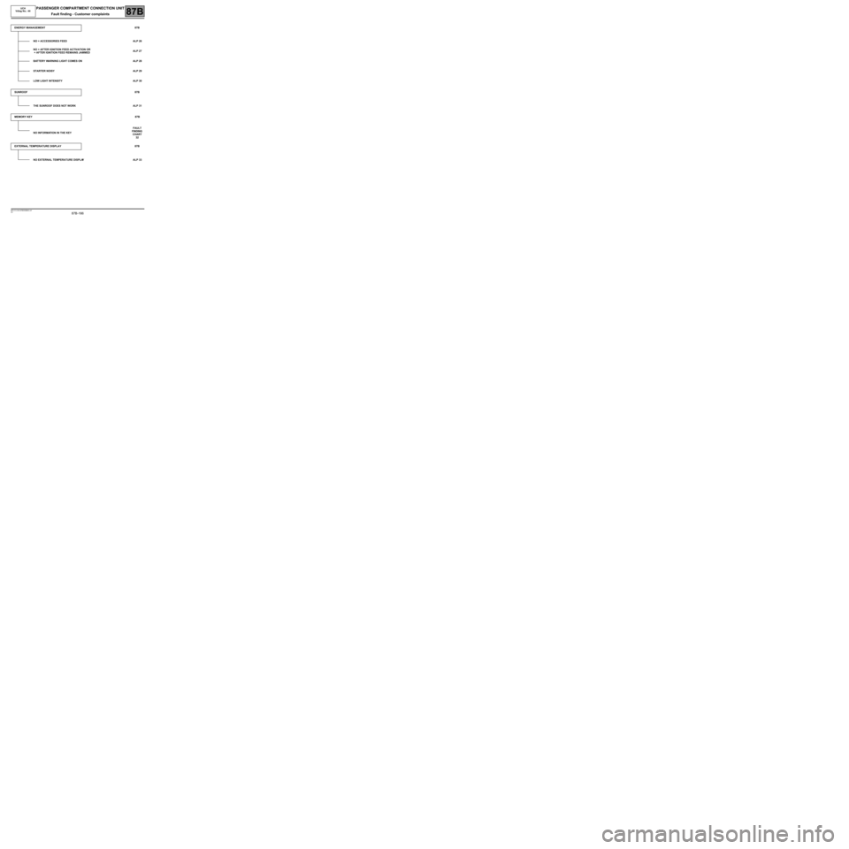
ENERGY MANAGEMENT87B
NO + ACCESSORIES FEED ALP 26
NO + AFTER IGNITION FEED ACTIVATION OR
+ AFTER IGNITION FEED REMAINS JAMMEDALP 27
BATTERY WARNING LIGHT COMES ON ALP 28
STARTER NOISY ALP 29
LOW LIGHT INTENSITY ALP 30
SUNROOF87B
THE SUNROOF DOES NOT WORK ALP 31
MEMORY KEY87B
NO INFORMATION IN THE KEYFAULT
FINDING
CHART
32
EXTERNAL TEMPERATURE DISPLAY 87B
NO EXTERNAL TEMPERATURE DISPLAYALP 33
Page 167 of 179
87B -167
MR-413-X44-87B000$912.mif
V5
87B
PASSENGER COMPARTMENT CONNECTION UNIT
Fault finding - Fault Finding Chart
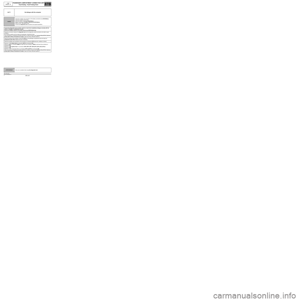
ALP 1 No dialogue with the computer
NOTESCheck the condition and connection of the battery connections (see 80A Battery).
Check the condition of the fuses.
Check the battery voltage (see 80A Battery).
Repair if necessary (see MR 411 Mechanical 80A Battery).
Switch on the + after ignition feed.
Connect the diagnostic tool and perform the required operations.
Connect the diagnostic tool to another vehicle to check that it establishes dialogue correctly with the
vehicle. If dialogue is established correctly.
Check the multiplex network of the faulty vehicle (see 88B Multiplexing).
Check the connection between the diagnostic tool and the diagnostic socket (connection and cable in good
condition),
the computer supplies and the engine and passenger compartment fuses.
If the connection or connections are faulty and there is a repair procedure (see Technical Note 6015A, Electrical
wiring repair, Wiring: Precautions for repair), repair the wiring, otherwise replace it.
Check the presence and condition of fuse F11 (20 A) on the passenger compartment fuse and relay box
(component code 1016). Replace the fuse if necessary.
Check the condition and connection of the connector of component 225 (tabs bent, oxidised or broken).
Check for + 12 V battery feed on connection BP19 of component 225.
Check for earth on connection MAM (for right-hand drive vehicles) or MAN (for left-hand drive vehicles) of
component 225.
Check for + after ignition feed on connections AP43, BP15, BPT, BP6, BP13, BP19, SP2, SP15 of
component 645.
Check for + 12 V accessories feed on connections SP2 and SP15 of component 645.
If the connection or connections are faulty and there is a repair procedure (see Technical Note 6015A, Electrical
wiring repair, Wiring: Precautions for repair), repair the wiring, otherwise replace it.
AFTER REPAIRCarry out a complete check using the diagnostic tool.
UCH_V44_ALP1
MR-413-X44-87B000$912.mif
UCH
Vdiag No.: 44
Page 169 of 179
87B -169
MR-413-X44-87B000$912.mif
V5
PASSENGER COMPARTMENT CONNECTION UNIT
Fault finding - Fault Finding Chart
UCH
Vdiag No.: 44
87B
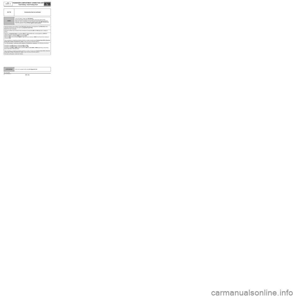
ALP 26 Accessories feed not activated
NOTESCheck the battery voltage (see 80A Battery).
Start the fault finding procedure with the ignition off and the vehicle locked.
When the vehicle is unlocked, the instrument panel should light up for a moment.
Otherwise, carry out fault finding on the multiplex network (see 88B, Multiplexing).
Check the operation of status ET239 "Ignition switch position".
Check the presence and condition of fuses F27 (5 A), depending on the equipment, and F29 (15 A) on the
passenger compartment fuse and relay box (component code 1016).
Replace the fuse if necessary.
Check the condition and connection of the connectors of components 645 and 1016 (tabs bent, oxidised or
broken).
Check for + accessories feed on connection SP2 (for vehicles fitted with a manual gearbox) or SP15 (for
vehicles fitted with a sequential gearbox) of component 645.
Check for earth on connection NAM of component 645.
Check for earth on the connection MAM (for right-hand drive vehicles) or MAN (for left-hand drive vehicles) of
component 645.
If the connection or connections are faulty and there is a repair procedure (see Technical Note 6015A, Electrical
wiring repair, Wiring: Precautions for repair), repair the wiring, otherwise replace it.
Check the insulation, continuity and the absence of interference resistance of the following connections:
Connection code SP2 between components 645 and 1016.
Connection code SP15 between components 645 and 1016.
Connection code MAN or MAM between component 645 and earth MAN or MAM (depending on the driving
layout; right-hand or left-hand drive).
If the connection or connections are faulty and there is a repair procedure (see Technical Note 6015A, Electrical
wiring repair, Wiring: Precautions for repair), repair the wiring, otherwise replace it.
If the fault is still present, contact the Techline.
AFTER REPAIRCarry out a complete check using the diagnostic tool.
UCH_V44_ALP26
Page 170 of 179

87B -170
MR-413-X44-87B000$912.mif
V5
PASSENGER COMPARTMENT CONNECTION UNIT
Fault finding - Fault Finding Chart
UCH
Vdiag No.: 44
87B
ALP 27No + after ignition feed activation or the + after ignition feed stays
jammed
NOTESCheck the battery voltage (see 80A Battery).
Check for faults using the diagnostic tool. Deal with the other faults first.
The + accessories feed activation function should be working; if not deal with ALP 26
Accessories feed not activated first.
Make sure that status ET239 Ignition switch position is working.
Make sure that status ET239 Ignition switch position
is workingApply the interpretation of the status if necessary.
Run a multiplex network test (see 88B, Multiplexing).
See 13B, Diesel injection or see 17B, Petrol injection.
AFTER REPAIRCarry out a complete check using the diagnostic tool.
UCH_V44_ALP27