ignition RENAULT TWINGO 2009 2.G Engine And Peripherals Passenger Compartment Connection Unit OBD Service Manual
[x] Cancel search | Manufacturer: RENAULT, Model Year: 2009, Model line: TWINGO, Model: RENAULT TWINGO 2009 2.GPages: 179, PDF Size: 0.57 MB
Page 89 of 179
87B-89
MR-413-X44-87B000$576.mif
V5
PASSENGER COMPARTMENT CONNECTION UNIT
Fault finding - Interpretation of statuses
UCH
Vdiag No.: 44
87B
ET027
WINDSCREEN WIPER PARK POSITION
NOTESNo faults should be present or stored.
Note:
The park position (rest position) is used as a reference point by the UCH when the
ignition is switched of f whilst the wipers are operating and is required for intermittent
wiper operation.
SPECIFICATIONSACTIVE
INACTIVE
Check that fuse F2 (15 A) is sound and correctly fitted in the passenger compartment fuse and relay box.
Replace the fuse if necessary.
Check the condition and connection of the 5-track (OR) connector on the windscreen wiper motor (component
code 212) and UCH connector PE3 (tabs bent, broken, oxidised).
Check that the earth on the MAS connection of component 212 is perfect.
If the connection is faulty and there is a repair procedure (see Technical Note 6015A, Electrical wiring repair,
Wiring: Precautions for repair), repair the wiring, otherwise replace it.
Check for + 12 V on connections 14A (high speed request) 14B and 14C (low speed request) of component
212 and on connector PE3 of the UCH (component code 645).
Check the mountings of the windscreen wiper motor (component code 212). Check that there is no point of
resistance on the windscreen wiper mechanism.
AFTER REPAIRRepeat the conformity check from the start.
Carry out fault finding on the system.
UCH_V44_ET027
Page 99 of 179
87B-99
MR-413-X44-87B000$576.mif
V5
PASSENGER COMPARTMENT CONNECTION UNIT
Fault finding - Interpretation of statuses
UCH
Vdiag No.: 44
87B
ET046
ENGINE IMMOBILISER
NOTESNo faults should be present or stored.
Apply the checks only if, the status remains ACTIVE after the ignition is switched off
and back on again under the following conditions.
SPECIFICATIONSACTIVE
INACTIVE
Check sure that ET239 Ignition switch position is + after ignition feed. Otherwise, refer to the interpretation of
this status.
Check that ET185 Key code received is YES.
Otherwise, refer to the interpretation of this status.
Check that ET181 Key allocated to vehicle is YES.
Otherwise, refer to the interpretation of this status.
Check that ET008 UCH blank is NO.
Otherwise, refer to the interpretation of this status.
Check that ET229 Injection immobiliser code is PROGRAMMED.
Otherwise, refer to the interpretation of this status.
Check that ET250 Injection is NOT PROTECTED.
Otherwise, refer to the interpretation of this status.
Carry out fault finding on the multiplex network (see 88B, Multiplexing).
If none of the computers on the vehicle has a malfunction and the statuses named in the notes are working
properly, contact Techline.
AFTER REPAIRRepeat the conformity check from the start.
Carry out fault finding on the system.
UCH_V44_ET046
Page 118 of 179
87B-118
MR-413-X44-87B000$624.mif
V5
PASSENGER COMPARTMENT CONNECTION UNIT
Fault finding - Interpretation of statuses
UCH
Vdiag No.: 44
87B
ET087
ONE-TOUCH WINDOW CONTROL/SUNROOF AUTHORISATION.
NOTESThere must be no present or stored faults.
Check the following configuration:
–Check that LC070 One-touch windows/SR* is With. Otherwise, perform CF173
One-touch windows/SR.
Authorisation by the UCH of the one-touch window winder and/or sunroof motor
function is present under the following conditions:
–+ ACCESSORIES FEED,
–+ AFTER IGNITION FEED,
–when the engine is running.
SPECIFICATIONSPRESENT
ABSENT
Check the condition and connection of the PE2 24-track UCH connector, (component code 645) (tabs bent,
broken, oxidised).
Check the condition and connection of the driver's electric window motor 6-track connector (component 203)
(tabs bent, broken, oxidised).
If the connector is faulty and there is a repair method (see Technical Note 6015A, Repairing electrical wiring,
Wiring: Precautions for repair), repair the wiring, otherwise replace the wiring.
If there is an electric sunroof, check that fuse F26 (20 A) is sound and correctly fitted in the passenger
compartment fuse and relay box (component code 1016).
Check the condition and connection of the connectors for component 1512.
With an electric sunroof, check the condition and connection of 4-track connector 339 in the A-pillar and the
sunroof computer 12-track connector (tabs bent, broken, oxidised).
If the connection is faulty and there is a repair procedure (see Technical Note 6015A, Electrical wiring repair,
Wiring: Precautions for repair), repair the wiring, otherwise replace it.
AFTER REPAIRRepeat the conformity check from the start.
Carry out fault finding on the system.
UCH_V44_ET087
Page 131 of 179
87B -131
MR-413-X44-87B000$624.mif
V5
PASSENGER COMPARTMENT CONNECTION UNIT
Fault finding - Interpretation of statuses
UCH
Vdiag No.: 44
87B
ET181
KEY ALLOCATED TO THE VEHICLE
NOTESThere must be no present or stored faults.
Apply the checks only if the status is NO with the ignition on.
SPECIFICATIONSYES
NO
Check that ET185 "Key code received" is "YES". If it is "NO", run fault finding on this status.
Switch the ignition off and then on again.
If the status remains NO, run command SC018 Key check.
If the fault is still present, replace the defective key(s) and allocate the keys using command SC015 Key
allocation.
If the fault is still present, contact the Techline.
AFTER REPAIRRepeat the conformity check from the start.
Carry out fault finding on the system.
UCH_V44_ET181
Page 132 of 179
87B -132
MR-413-X44-87B000$624.mif
V5
PASSENGER COMPARTMENT CONNECTION UNIT
Fault finding - Interpretation of statuses
UCH
Vdiag No.: 44
87B
ET185
KEY CODE RECEIVED
NOTESThere must be no present or stored faults.
Apply the checks only if the status is NO with the ignition on.
SPECIFICATIONSYES
NO
Check that there are no powerful electromagnetic wave sources (CB (Citizen Band), mobile phone in close
proximity to the transponder ring).
Switch the ignition off and then on again.
Check that fuse F8 (15 A) is sound and correctly fitted in the passenger compartment fuse and relay box.
Replace the fuse if necessary.
Try the vehicle's second key.
If the status changes to YES, replace the first key and program the keys using command SC015 Key allocation.
This status tells you whether the UCH has received the immobiliser code from the key.
If the status remains NO, check the connection between the transponder ring (component code 1618) and the
UCH (component code 645).
Check the + 12 V feed on connection AP43 of component 1618.
If the connection is faulty and there is a repair procedure (see Technical Note 6015A, Electrical wiring repair,
Wiring: Precautions for repair), repair the wiring, otherwise replace it.
Check that the earth on track 2 of the transponder ring is in perfect condition.
Check the insulation, the continuity and the absence of interference resistance on the following
connections:
●Connection code AP43 between components 1016 and 1618.
●Connection code 80X between components 645 and 1618.
●Connection code 80Y between components 645 and 1618.
●Connection code NAM between component 1618 and earth.
If the connection or connections are faulty and there is a repair procedure (see Technical Note 6015A, Electrical
wiring repair, Wiring: Precautions for repair), repair the wiring, otherwise replace it.
If the fault is still present, contact the Techline.
AFTER REPAIRRepeat the conformity check from the start.
Carry out fault finding on the system.
UCH_V44_ET185
Page 133 of 179
87B -133
MR-413-X44-87B000$624.mif
V5
PASSENGER COMPARTMENT CONNECTION UNIT
Fault finding - Interpretation of statuses
UCH
Vdiag No.: 44
87B
* RF: radio frequencyET186
ET189
SHORT PRESS ON DOOR CLOSING BUTTON
DOOR OPENING BUTTON PRESSED
NOTESThere must be no present or stored faults.
Check that LC097 Key type is definitely RF*. Otherwise run CF195 Key type and
select RF*.
Check the operation of statuses ET045 R.F.* signal received and ET193 RF* signal
from a key allocated to the vehicle.
Note:
The key must not be in the ignition switch.
Signal can be interpreted if the ignition is switched off (key removed from the
ignition switch).
SPECIFICATIONSACTIVE
INACTIVE
Check the condition of the key battery and of the button contacts.
Replace the battery if necessary.
Try the vehicle's second key.
If the status changes to Active, replace the first key and allocate the keys using command SC015 Key allocation.
If the fault is still present, contact the Techline.
AFTER REPAIRRepeat the conformity check from the start.
Carry out fault finding on the system.
UCH_V44_ET186 / UCH_V44_ET189
Page 135 of 179
87B -135
MR-413-X44-87B000$624.mif
V5
UCH
Vdiag No.: 44PASSENGER COMPARTMENT CONNECTION UNIT
Fault finding - Interpretation of statuses87B
* Powerlatch: Time required for injection computer supply after + 12 V after ignition feed cut-off. ET229
INJECTION IMMOBILISER CODE
NOTESThere must be no present or stored faults.
Only apply the checks if the status is NOT PROGRAMMED or NOT DETERMINED
after activating the + After ignition feed for 20 seconds; switch off the ignition, wait for
the end of Powerlatch (20 minutes maximum), and then switch on the ignition again.
SPECIFICATIONSUNDETERMINED
NOT PROGRAMMED
PROGRAMMED
STATUS
NOT
PROGRAMMED
Run command SC017 Program injection immobiliser code.
STATUS
UNDETERMINEDSwitch the ignition off and then on again.
First check whether statuses ET046 Immobliser, ET181 Key allocated to the vehicle
and ET239 Position of the ignition switch are correct.
Carry out a multiplex network test (see 88B, Multiplexing).
Carry out fault finding on the injection system (see 13B, Diesel injection or 17B,
Petrol injection).
Check the condition of the injection computer connectors.
Check that the + 12 V supply and injection computer earth (component code 120) are
in order.
If the fault is still present, contact the Techline.
AFTER REPAIRRepeat the conformity check from the start.
Carry out fault finding on the system.
UCH_V44_ET229
Page 136 of 179
87B -136
MR-413-X44-87B000$624.mif
V5
PASSENGER COMPARTMENT CONNECTION UNIT
Fault finding - Interpretation of statuses
UCH
Vdiag No.: 44
87B
ET239
IGNITION SWITCH POSITION
NOTESThere must be no present or stored faults.
SPECIFICATIONS+ APC
+ START
+ ACCESSORIES FEED
Check the correct position and condition of fuses F2 (60A) in the engine fuse and relay box (component code
597) and F8 (15A) in the passenger compartment fuse and relay box (component code 1016).
Replace the fuse if necessary.
Check the condition and connection of the starter switch connector (component code 104) (tabs bent, broken,
oxidised).
Check the condition and connection of the PE1 connector of the UCH, (component code 645) (tabs bent,
oxidised, broken).
If the connector is faulty and there is a repair method (see Technical Note 6015A, Repairing electrical wiring,
Wiring: Precautions for repair), repair the wiring, otherwise replace the wiring.
Check for +12 V on connection AP29 of component 232.
Check the insulation, continuity and the absence of interference resistance on the connections between the
UCH (component code 645) and the ignition switch (component 104):
●Connection code A between components 104 and 1016.
●Connection code BP12 between components 104 and 597.
●Connection code AP43 between components 1016 and 645.
●Connection code D between components 104 and 232.
●Connection code 1B between components 232 and 645.
●Connection code AP29 between components 1016 and 232.
If the connection or connections are faulty and there is a repair procedure (see Technical Note 6015A, Electrical
wiring repair, Wiring: Precautions for repair), repair the wiring, otherwise replace it.
If the connections are in order, replace the ignition switch (component code 104).
(See MR 411 Mechanical 82A, Immobiliser, Ignition switch: Removal - Refitting).
If the fault is still present, contact the Techline.
AFTER REPAIRRepeat the conformity check from the start.
Carry out fault finding on the system.
UCH_V44_ET239
Page 138 of 179
87B -138
MR-413-X44-87B000$624.mif
V5
PASSENGER COMPARTMENT CONNECTION UNIT
Fault finding - Interpretation of statuses
UCH
Vdiag No.: 44
87B
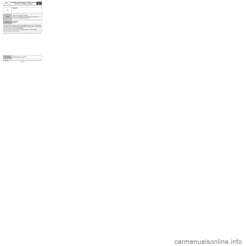
*Powerlatch: Time required for injection computer supply after + 12 V after ignition feed cut-off to the ignition switch. ET250
INJECTION
NOTESThere must be no present or stored faults.
Switch on the + after ignition feed for 20 seconds, switch off the ignition, wait until the
end of Powerlatch* (20 minutes maximum), then switch on the ignition again.
Check that the immobiliser warning light remains lit.
SPECIFICATIONSNOT PROTECTED
PROTECTED
After the setpoint has been obtained, if the status remains PROTECTED, first check that statuses ET046 Engine
immobiliser, ET181 Key allocated to vehicle and ET229 Injection immobiliser code are operating correctly.
Carry out a multiplex network test (see 88B, Multiplexing).
Carry out fault finding on the injection system (see 13B, Diesel injection or 17B, Petrol injection).
If the fault is still present, contact the Techline.
AFTER REPAIRRepeat the conformity check from the start.
Carry out fault finding on the system.
UCH_V44_ET250
Page 147 of 179
87B -147
MR-413-X44-87B000$720.mif
V5
PASSENGER COMPARTMENT CONNECTION UNIT
Fault finding - Interpretation of parameters
UCH
Vdiag No.: 44
87B
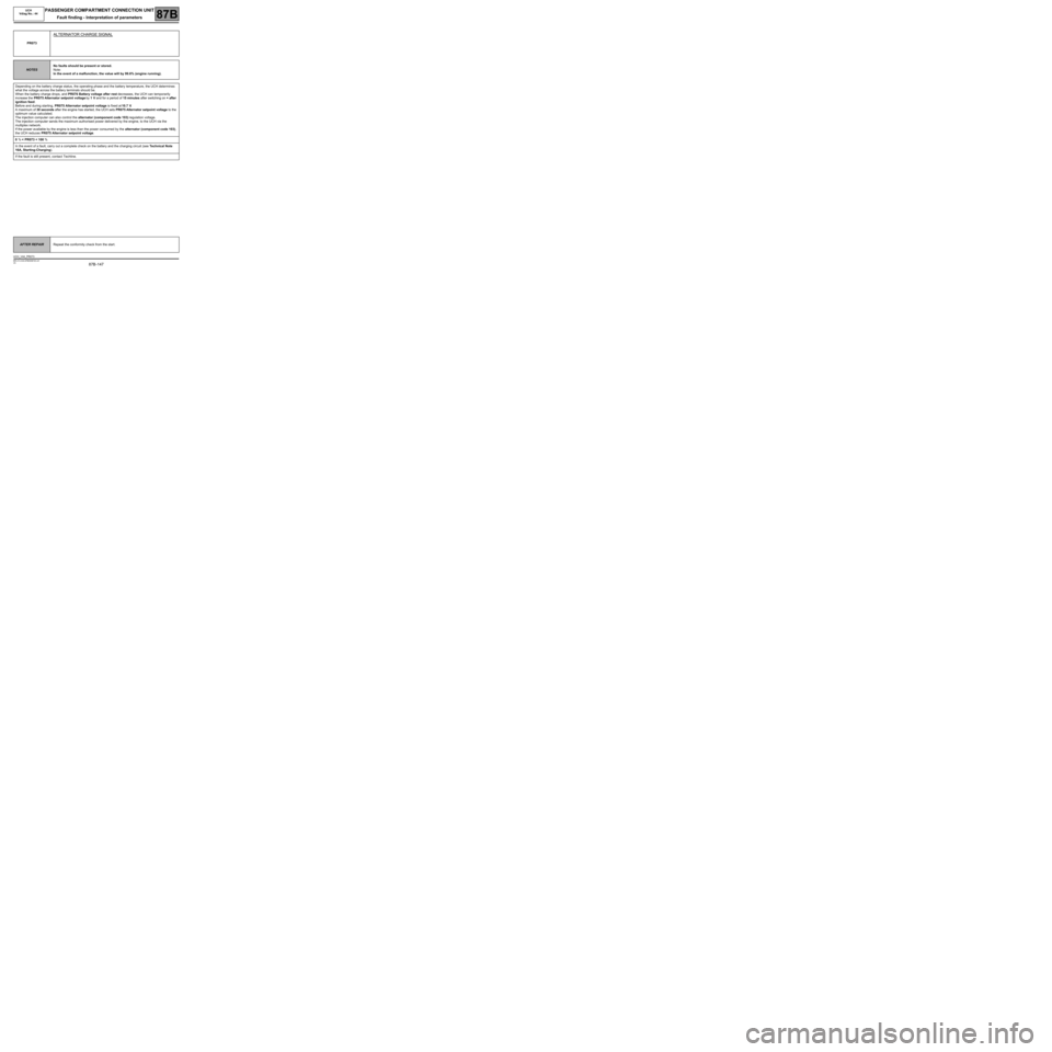
PR073
ALTERNATOR CHARGE SIGNAL
NOTESNo faults should be present or stored.
Note:
In the event of a malfunction, the value will by 99.6% (engine running).
Depending on the battery charge status, the operating phase and the battery temperature, the UCH determines
what the voltage across the battery terminals should be.
When the battery charge drops, and PR076 Battery voltage after rest decreases, the UCH can temporarily
increase the PR075 Alternator setpoint voltage by 1 V and for a period of 15 minutes after switching on + after
ignition feed.
Before and during starting, PR075 Alternator setpoint voltage is fixed at 10.7 V.
A maximum of 30 seconds after the engine has started, the UCH sets PR075 Alternator setpoint voltage to the
optimum value calculated.
The injection computer can also control the alternator (component code 103) regulation voltage.
The injection computer sends the maximum authorised power delivered by the engine, to the UCH via the
multiplex network.
If the power available by the engine is less than the power consumed by the alternator (component code 103),
the UCH reduces PR075 Alternator setpoint voltage.
0 % < PR073 < 100 %
In the event of a fault, carry out a complete check on the battery and the charging circuit (see Technical Note
16A, Starting-Charging).
If the fault is still present, contact Techline.
AFTER REPAIRRepeat the conformity check from the start.
UCH_V44_PR073