check engine light RENAULT TWINGO 2009 2.G Engine And Peripherals Passenger Compartment Connection Unit OBD Workshop Manual
[x] Cancel search | Manufacturer: RENAULT, Model Year: 2009, Model line: TWINGO, Model: RENAULT TWINGO 2009 2.GPages: 179, PDF Size: 0.57 MB
Page 25 of 179
87B-25
MR-413-X44-87B000$384.mif
V5
87B
PASSENGER COMPARTMENT CONNECTION UNIT
Fault finding - Interpretation of faults
DF001
PRESENT
OR
STOREDUCH
1.DEF : Internal electronic fault
NOTESConditions for applying the fault finding procedure to stored faults:
The fault is declared present after the ignition is switched off and back on.
If the fault is stored, clear the fault, switch off the ignition and disconnect the F8 (15A) fuse of the UCH supply
(component code 645) on the passenger compartment fuse and relay box (component code 1016).
–Refit the fuse and switch the ignition back on.
–Request locking and then unlocking, then start the engine.
Check the condition and connection of the PE1, PE2 and PE3 connectors of the UCH (component code 645)
(tabs pushed back, oxidised, broken).
If the connector(s) are faulty and there is a repair procedure (see Technical Note 6015A, Electrical wiring
repair, Wiring: Precautions for repair), repair the wiring, otherwise replace the wiring.
Check for + after ignition feed on connection AP43 of component 645.
Check for + accessories feed on connection SP2 (for vehicles fitted with a manual gearbox) or SP15
(for vehicles fitted with a sequential gearbox) of component 645.
Check for earth on connection NAM of component 645. Check the earth on connection MAM of component 645.
If the connection or connections are faulty and there is a repair procedure (see Technical Note 6015A, Electrical
wiring repair, Wiring: Precautions for repair), repair the wiring, otherwise replace it.
If the fault reappears as stored, contact Techline.
If the fault does not reappear, switch the lighting, wipers, vehicle locking and climate control request controls on
and off several times, then read the faults again.
If the fault is still present. Do not operate on the computer, contact Techline.
AFTER REPAIRIf the computer has been replaced (at the request of the Techline): reconfigure the new
UCH (see Configurations and programming).
Deal with any other faults.
UCH_V44_DF001
MR-413-X44-87B000$384.mif
UCH
Vdiag No.: 44
Page 38 of 179
87B-38
MR-413-X44-87B000$384.mif
V5
PASSENGER COMPARTMENT CONNECTION UNIT
Fault finding - Interpretation of faults
UCH
Vdiag No.: 44
87B
*RF: radio frequencyDF054
PRESENT
OR
STORED
COMPUTER
The radiofrequency receiver inside the UCH computer does not work
1.DEF : Internal electronic fault
NOTESConditions for applying the fault finding procedure to stored faults:
–The fault is declared present after the ignition has been switched on.
If the fault is stored, switch off the ignition and check the F8 (15A) fuse of the UCH supply (component
code 645) on the passenger compartment fuse and relay box (component code 1016).
–Replace the fuse if necessary, clear the fault and switch on the ignition again.
–Request locking and then unlocking, then start the engine.
Check for + after ignition feed on connections AP43, BP15, APT, BP6, BP13, BP19, SP2, SP15 of
component 645.
Check for + 12 V accessories feed on connections SP2 and SP15 of component 645.
Check for earth on connections MAN and NAM of component 645.
If the connection or connections are faulty and there is a repair procedure (see Technical Note 6015A, Electrical
wiring repair, Wiring: Precautions for repair), repair the wiring, otherwise replace it.
Check that status ET045 “RF* signal received” is “Yes” by pressing the locking button on the key, if when
pressing the status is “No” check the battery and the conformity of the key.
If the fault does not reappear, switch the lighting, wipers, vehicle locking and climate control request controls on
and off several times, then read the faults again.
If the fault is still present. Do not operate on the computer, contact Techline.
AFTER REPAIRCarry out another fault finding check on the system.
Clear the stored faults.
Deal with any other faults.
UCH_V44_DF054
Page 63 of 179
87B-63
MR-413-X44-87B000$432.mif
V5
PASSENGER COMPARTMENT CONNECTION UNIT
Fault finding - Interpretation of faults
UCH
Vdiag No.: 44
87B
DF137
PRESENT
OR
STOREDUCH - ALTERNATOR CONNECTION
CO : Open circuit
1.DEF : Dialogue disrupted
CC.0 : Short circuit
NOTESThe fault is declared present after:
Switching on the ignition, starting the engine and waiting 30 seconds.
Check that the engine type is entered correctly using the configuration reading "Check
that LC023 Engine Type is correct". Otherwise perform CF028 Engine type.
Customer complaint:
The battery warning light comes on when the fault appears and goes out 10 seconds
after the fault disappears.
Note:
For petrol vehicles, the fault can be linked to a fault on the anti-interference capacitor
if it is present.
Check the condition and connection of the 2-track connector of the alternator (component code 103) and
connector PE1 of component 645 (tabs bent, oxidised, broken).
Check that the voltage is between 5 V and 10 V on connection 2N between components 103 and 645.
Check the continuity and insulation of the following connections:
●Connection code 2N between components 103 and 645.
●Connection code BPDA between components 103 and 163.
If the connection or connections are faulty and there is a repair procedure (see Technical Note 6015A, Electrical
wiring repair, Wiring: Precautions for repair), repair the wiring, otherwise replace it.
If the problem is still present, contact the Techline.
AFTER REPAIRCarry out another fault finding check on the system.
Clear the stored faults.
Deal with any other faults.
UCH_V44_DF135 / UCH_V44_DF136
Page 64 of 179
87B-64
MR-413-X44-87B000$432.mif
V5
PASSENGER COMPARTMENT CONNECTION UNIT
Fault finding - Interpretation of faults
UCH
Vdiag No.: 44
87B
DF138
PRESENT
OR
STOREDALTERNATOR
1.DEF: Mechanical or electrical fault
2.DEF: Temperature fault
NOTESThe fault is declared present after:
Switching on the ignition, starting the engine and waiting 1 minute in the event of an
electrical or mechanical fault.
In the event of a temperature fault, run the engine until the engine cooling fans are
triggered.
Effect on system:
The fault is hidden for 3 seconds, the alternator voltage setpoint is 14.3 V and the on-
board network voltage is equal to 14.3 V if the alternator can still regulate. Regulation
resumes as soon as the fault disappears.
Effect on system:
The battery warning light comes on when the fault appears and goes out as soon as
the fault disappears.
Check for the presence, condition and fitting of the alternator belt. (See MR 411, Mechanical, 11A, Top and front
of engine, Accessories belt: Removal - Refitting).
Remove the accessories belt (MR411, Mechanical, 11A Top and front of engine, Accessories belt, Removal -
Refitting).
Check that the alternator pulley is not offset against its axis.
Check that the alternator pulley turns freely on its axis.
Check that the continuity and electrical insulation of the rotor coil is correct. Check that there is no sign of the rotor
overheating. (See MR 411, Mechanical 16A, Starting - Charging, Charging circuit: Check).
Perform a charging circuit test (see 80A, Battery).
If the fault is still present, replace the alternator (component code 103) (see MR 411, Mechanical 16A,
Starting - Charging, Alternator: Removal - Refitting).
AFTER REPAIRCarry out another fault finding check on the system.
Clear the stored faults.
Deal with any other faults.
UCH_V44_DF138
Page 66 of 179
87B-66
MR-413-X44-87B000$432.mif
V5
PASSENGER COMPARTMENT CONNECTION UNIT
Fault finding - Interpretation of faults
UCH
Vdiag No.: 44
87B
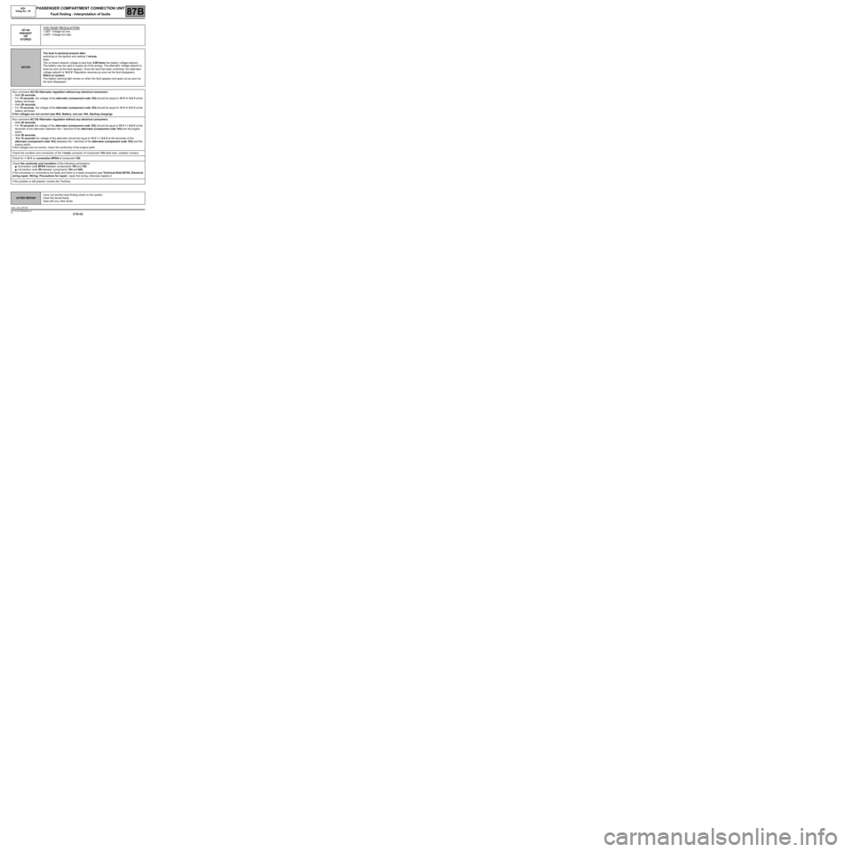
DF140
PRESENT
OR
STOREDVOLTAGE REGULATION
1.DEF: Voltage too low
2.DEF: Voltage too high
NOTESThe fault is declared present after:
switching on the ignition and waiting 1 minute.
Note:
The on-board network voltage is less than 0.89 times the battery voltage setpoint.
The battery may be used to supply all of the energy. The alternator voltage setpoint is
fixed as soon as the fault appears. Once the fault has been confirmed, the alternator
voltage setpoint is 14.3 V. Regulation resumes as soon as the fault disappears.
Effect on system:
The battery warning light comes on when the fault appears and goes out as soon as
the fault disappears.
Run command AC130 Alternator regulation without any electrical consumers:
–Wait 20 seconds.
–For 10 seconds, the voltage of the alternator (component code 103) should be equal to 15 V +/- 0.2 V at the
battery terminals.
–Wait 20 seconds.
–For 10 seconds, the voltage of the alternator (component code 103) should be equal to 13 V +/- 0.2 V at the
battery terminals.
If the voltages are not correct (see 80A, Battery, and see 16A, Starting charging).
Run command AC130 Alternator regulation without any electrical consumers:
–Wait 20 seconds.
–For 10 seconds the voltage of the alternator (component code 103) should be equal to 15 V + /- 0.2 V at the
terminals of the alternator (between the + terminal of the alternator (component code 103) and the engine
earth).
–Wait 20 seconds.
– For 10 seconds the voltage of the alternator should be equal to 13 V + /- 0.2 V at the terminals of the
alternator (component code 103) (between the + terminal of the alternator (component code 103) and the
engine earth).
If the voltages are not correct, check the conformity of the engine earth.
Check the condition and connection of the 1-track connector of component 103 (tabs bent, oxidised, broken).
Check for + 12 V on connection BPDA of component 103.
Check the continuity and insulation of the following connections:
●Connection code BPDA between components 103 and 163.
●Connection code 2N between components 103 and 645.
If the connection or connections are faulty and there is a repair procedure (see Technical Note 6015A, Electrical
wiring repair, Wiring: Precautions for repair), repair the wiring, otherwise replace it.
If the problem is still present, contact the Techline.
AFTER REPAIRCarry out another fault finding check on the system.
Clear the stored faults.
Deal with any other faults.
UCH_V44_DF140
Page 74 of 179
87B-74
MR-413-X44-87B000$480.mif
V5
UCH
Vdiag No.: 44PASSENGER COMPARTMENT CONNECTION UNIT
Fault finding - Conformity check87B
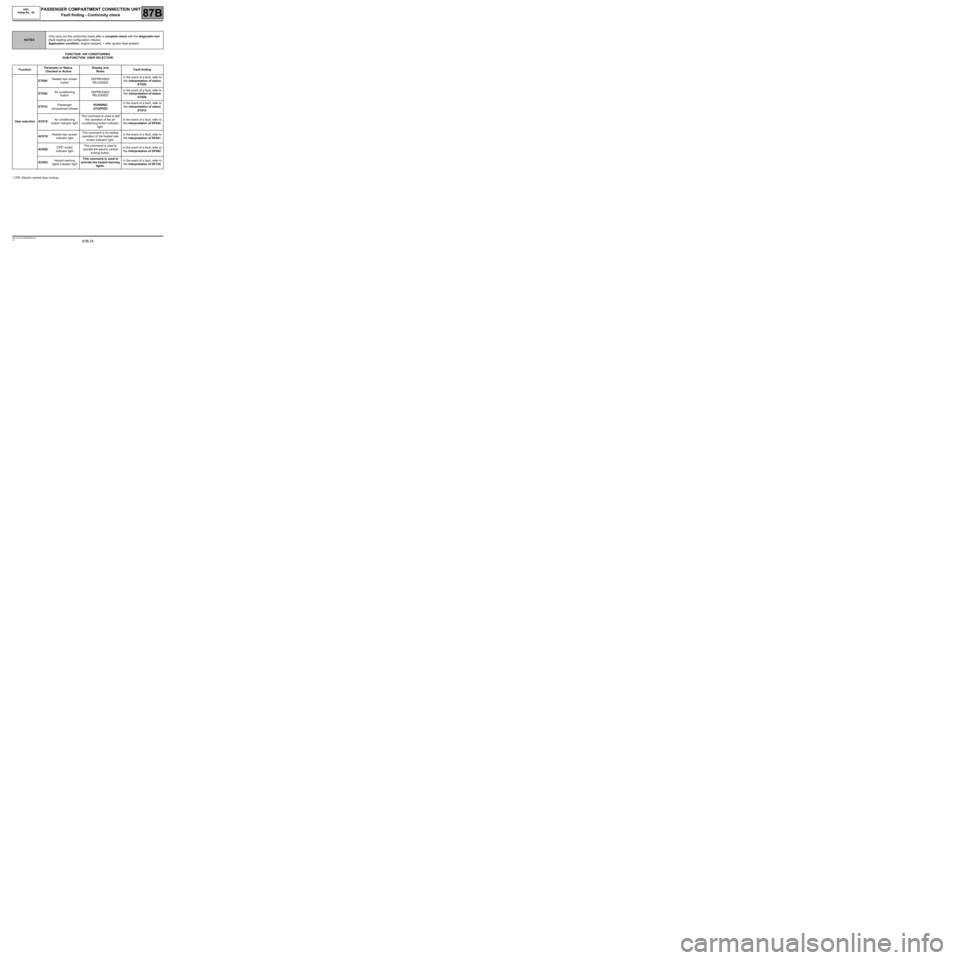
FUNCTION: AIR CONDITIONING
SUB-FUNCTION: USER SELECTION
* CPE: Electric central door locking.
NOTESOnly carry out this conformity check after a complete check with the diagnostic tool
(fault reading and configuration checks).
Application condition: engine stopped, + after ignition feed present.
FunctionParameter or Status
Checked or ActionDisplay and
NotesFault finding
User selectionET028:Heated rear screen
buttonDEPRESSED
RELEASEDIn the event of a fault, refer to
the interpretation of status
ET028.
ET029:Air conditioning
buttonDEPRESSED
RELEASEDIn the event of a fault, refer to
the interpretation of status
ET029.
ET015:Passenger
compartment blowerRUNNING
STOPPEDIn the event of a fault, refer to
the interpretation of status
ET015.
AC015:Air conditioning
button indicator lightThis command is used to test
the operation of the air
conditioning button indicator
light.In the event of a fault, refer to
the interpretation of DF042.
AC019:Heated rear screen
indicator lightThis command is for testing
operation of the heated rear
screen indicator light.In the event of a fault, refer to
the interpretation of DF041.
AC020:CPE* button
indicator lightThis command is used to
operate the electric central
locking button.In the event of a fault, refer to
the interpretation of DF082.
AC052:Hazard warning
lights indicator lightThis command is used to
activate the hazard warning
lights.In the event of a fault, refer to
the interpretation of DF134.
Page 77 of 179
87B-77
MR-413-X44-87B000$480.mif
V5
UCH
Vdiag No.: 44PASSENGER COMPARTMENT CONNECTION UNIT
Fault finding - Conformity check87B
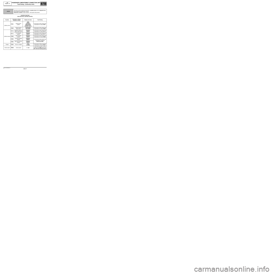
LIGHTING FUNCTION
SUB-FUNCTION: LIGHTING CONTROL
NOTESOnly carry out this conformity check after a complete check with the diagnostic tool
(fault reading and configuration checks).
Application condition: engine stopped, + after ignition feed present.
FunctionParameter or Status
Checked or ActionDisplay and notes Fault finding
Lighting controlET081:Lighting switch
positionSIDE
DIPPED
MAIN BEAM
HEADLIGHTS
HAZARD LIGHTSIn the event of a fault, refer to the
interpretation for status ET081.
ET085:Hazard warning
lights buttonDEPRESSED
RELEASEDIn the event of a fault, refer to the
interpretation for status ET085.
Lighting requestET115:Request to switch on
lights by light sensorPRESENT
ABSENTIn the event of a fault, refer to the
interpretation for status ET115.
ET111:Front fog lights
requestPRESENT
ABSENTIn the event of a fault, refer to the
interpretation for status ET111.
ET082:Rear fog lights
requestPRESENT
ABSENTIn the event of a fault, refer to the
interpretation for status ET082.
ET083:Left-hand indicator
requestPRESENT
ABSENTIn the event of a fault, refer to the
interpretation of statuses
ET083 and ET084.
ET084:Right-hand indicator
requestPRESENT
ABSENT
TailgateET463:Door(s) or tailgateOPEN
CLOSEDIn the event of a fault, consult the
interpretation of status ET463.
Vehicle speedPR008:Vehicle speed0 mphIn the event of a fault, run fault
finding on the ABS system (see
38C, Anti-lock braking system).
Page 78 of 179
87B-78
MR-413-X44-87B000$480.mif
V5
UCH
Vdiag No.: 44PASSENGER COMPARTMENT CONNECTION UNIT
Fault finding - Conformity check87B
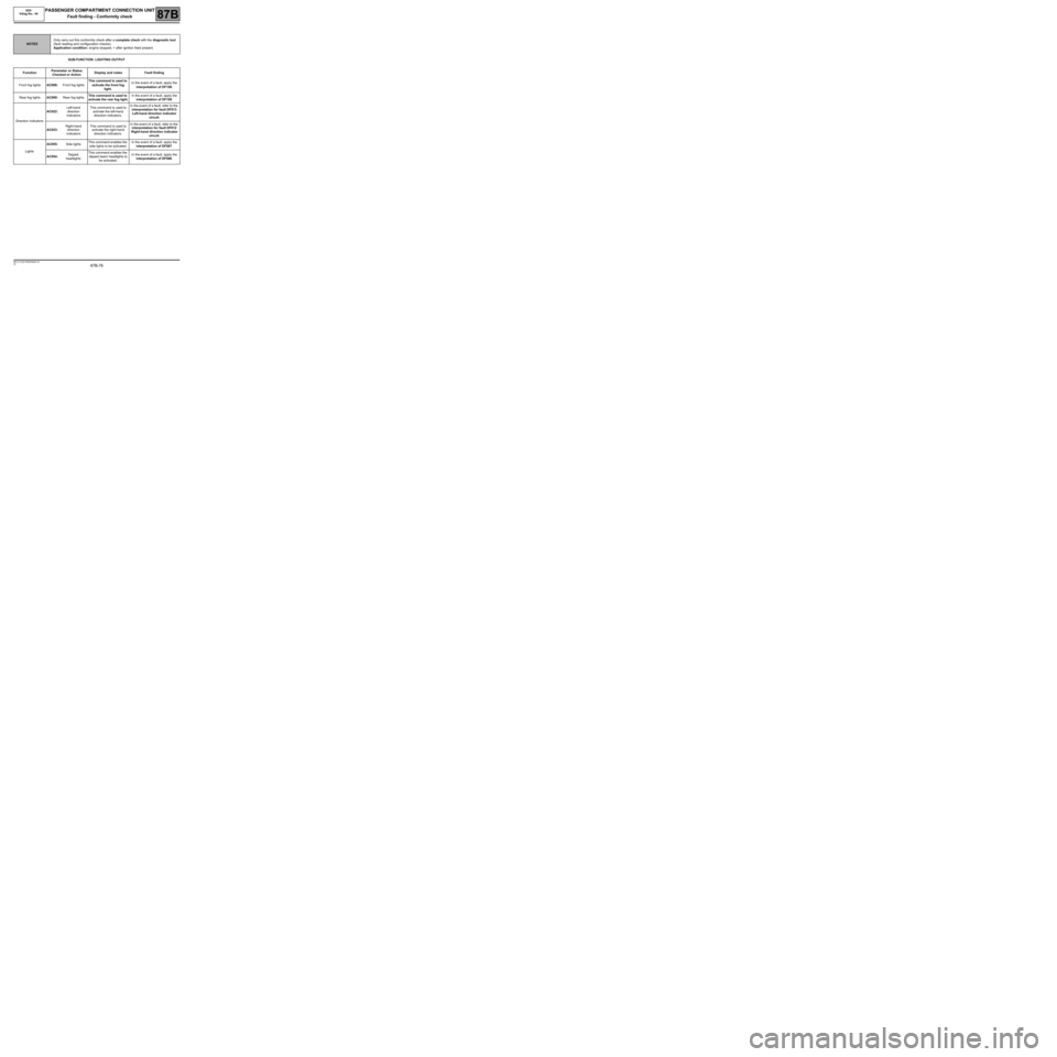
SUB-FUNCTION: LIGHTING OUTPUT
NOTESOnly carry out this conformity check after a complete check with the diagnostic tool
(fault reading and configuration checks).
Application condition: engine stopped, + after ignition feed present.
FunctionParameter or Status
Checked or ActionDisplay and notes Fault finding
Front fog lightsAC008:Front fog lightsThis command is used to
activate the front fog
light.In the event of a fault, apply the
interpretation of DF108.
Rear fog lightsAC009:Rear fog lightsThis command is used to
activate the rear fog light.In the event of a fault, apply the
interpretation of DF109.
Direction indicatorsAC022:Left-hand
direction
indicatorsThis command is used to
activate the left-hand
direction indicators.In the event of a fault, refer to the
interpretation for fault DF013
Left-hand direction indicator
circuit.
AC023:Right-hand
direction
indicatorsThis command is used to
activate the right-hand
direction indicators.In the event of a fault, refer to the
interpretation for fault DF012
Right-hand direction indicator
circuit.
LightsAC055:Side lightsThis command enables the
side lights to be activated.In the event of a fault, apply the
interpretation of DF087.
AC054:Dipped
headlightsThis command enables the
dipped beam headlights to
be activated.In the event of a fault, apply the
interpretation of DF088.
Page 79 of 179
87B-79
MR-413-X44-87B000$480.mif
V5
UCH
Vdiag No.: 44PASSENGER COMPARTMENT CONNECTION UNIT
Fault finding - Conformity check87B
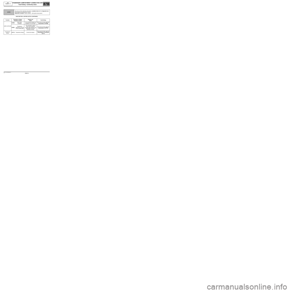
SUB-FUNCTION: LIGHTING OUTPUT (CONTINUED)
NOTESOnly carry out this conformity check after a complete check with the diagnostic tool
(fault reading and configuration checks).
Application condition: engine stopped, + after ignition feed present.
FunctionParameter or Status
Checked or ActionDisplay and
NotesFault finding
Lights (continued)AC062:Main beam
headlightsThis command enables the
headlights to be activated.In the event of a fault, apply the
interpretation of DF098.
AC063:Progressive
switching on and off
of the courtesy lightThis command is used to
check that the gradual
courtesy light activation and
deactivation function is
operating correctly.In the event of a fault, apply the
interpretation of DF139.
Temperature
displayAC110:Temperature display Controls the display.In the event of a fault, apply the
interpretation of command
AC110.
Page 95 of 179
87B-95
MR-413-X44-87B000$576.mif
V5
UCH
Vdiag No.: 44PASSENGER COMPARTMENT CONNECTION UNIT
Fault finding - Interpretation of statuses87B
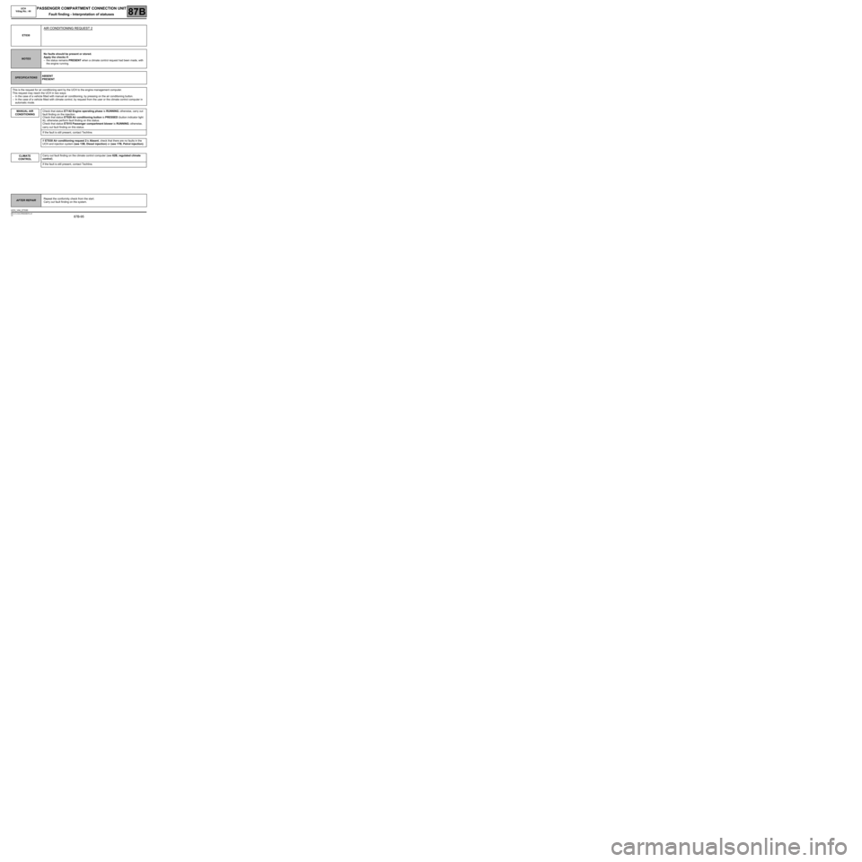
ET030
AIR CONDITIONING REQUEST 2
NOTESNo faults should be present or stored.
Apply the checks if:
–the status remains PRESENT when a climate control request had been made, with
the engine running.
SPECIFICATIONSABSENT
PRESENT
This is the request for air conditioning sent by the UCH to the engine management computer.
This request may reach the UCH in two ways:
–In the case of a vehicle fitted with manual air conditioning, by pressing on the air conditioning button.
–In the case of a vehicle fitted with climate control, by request from the user or the climate control computer in
automatic mode.
MANUAL AIR
CONDITIONING
Check that status ET142 Engine operating phase is RUNNING; otherwise, carry out
fault finding on the injection.
Check that status ET029 Air conditioning button is PRESSED (button indicator light
lit), otherwise perform fault finding on this status.
Check that status ET015 Passenger compartment blower is RUNNING; otherwise,
carry out fault finding on this status.
If the fault is still present, contact Techline.
If ET030 Air conditioning request 2 is Absent, check that there are no faults in the
UCH and injection system (see 13B, Diesel injection) or (see 17B, Petrol injection).
CLIMATE
CONTROLCarry out fault finding on the climate control computer (see 62B, regulated climate
control).
If the fault is still present, contact Techline.
AFTER REPAIRRepeat the conformity check from the start.
Carry out fault finding on the system.
UCH_V44_ET030