fuel filter RENAULT TWINGO 2009 2.G Engine And Peripherals Workshop Manual
[x] Cancel search | Manufacturer: RENAULT, Model Year: 2009, Model line: TWINGO, Model: RENAULT TWINGO 2009 2.GPages: 652
Page 403 of 652
13B-42
DIESEL INJECTION
High pressure pipe between rail and injector: Removal - Refitting
K9K
13B
aFit and lock a new clip between the high pressure
pipes between the rail and the injectors.
aUsing the (Mot. 1746), tighten to torque:
-the high pressure pipe unions between the
pump and the yellow rail (24 Nm),
-the high pressure pipe unions between the
pump and the silver rail (28 Nm).
III - FINAL OPERATION.
aRefit:
-the channel,
-the neck nut.
aFit the neck wiring harness.
aClip the neck on.
aConnect to the high pressure pump:
-the diesel fuel supply pipe,
-the diesel return pipe to the diesel filter.
aRemove the protection on the alternator and starter.
aConnect the connectors:
-the heater plugs,
-the injectors,
-the flow actuator,
-diesel fuel temperature sensor.
aRemove the blanking cover protecting the dipstick
guide inlet orifice on the cylinder block.
aRefit:
-the dipstick guide,
-the dipstick guide nut,
-the oil level dipstick.
aRefit the neck nuts.
aPrime the fuel circuit with a manual priming pump
until the disconnected pipes are filled with fuel; if
necessary, bleed the fuel filter (see 13A, Fuel sup-
ply, Fuel filter: Removal - Refitting, page 13A-4) .
aCheck that there are no fuel leaks.
aConnect the battery (see ) (MR 411, 80A, Battery).
aCheck the high pressure circuit (see 13B, Diesel in-
jection, High pressure pipe: Check, page 13B-34)
.
aUse the Diagnostic tool to check for an absence of
stored faults; deal with these and clear them as nec-
essary.
aRefit the engine cover.
Page 406 of 652
13B-45
DIESEL INJECTION
Injector rail: Removal - Refitting
K9K
13B
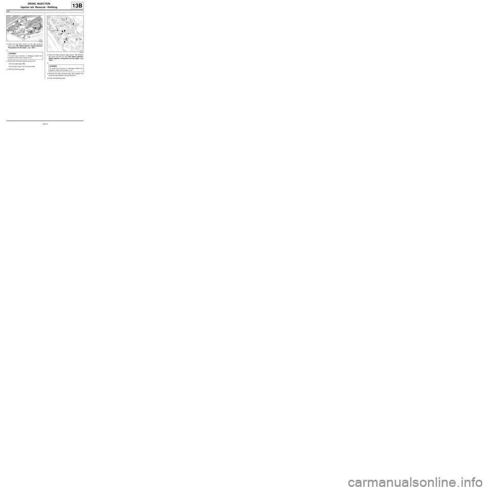
aClean the fuel pipe unions on the high pressure
pump (see 13B, Diesel injection, Diesel injection:
Precautions for the repair, page 13B-1) .
a
aDisconnect the high pressure pump from:
-the fuel supply pipe (10) ,
-the fuel return pipe (11) to the fuel filter.
aInsert the blanking plugs.aClean the high pressure pipe unions (12) between
the pump and the rail (see 13B, Diesel injection,
Diesel injection: Precautions for the repair, page
13B-1) .
a
aRemove the high pressure pipe (12) between the
pump and the injection rail and discard it.
aInsert the blanking plugs.
121423
WARNING
To avoid any corrosion or damage, protect the
areas on which fuel is likely to run.127901
WARNING
To avoid any corrosion or damage, protect the
areas on which fuel is likely to r un.
Page 408 of 652
13B-47
DIESEL INJECTION
Injector rail: Removal - Refitting
K9K
13B
aRemove the blanking plugs.
aFit the injector rail.
aFit the injector rail nuts without tightening them.
III - FINAL OPERATION.
a
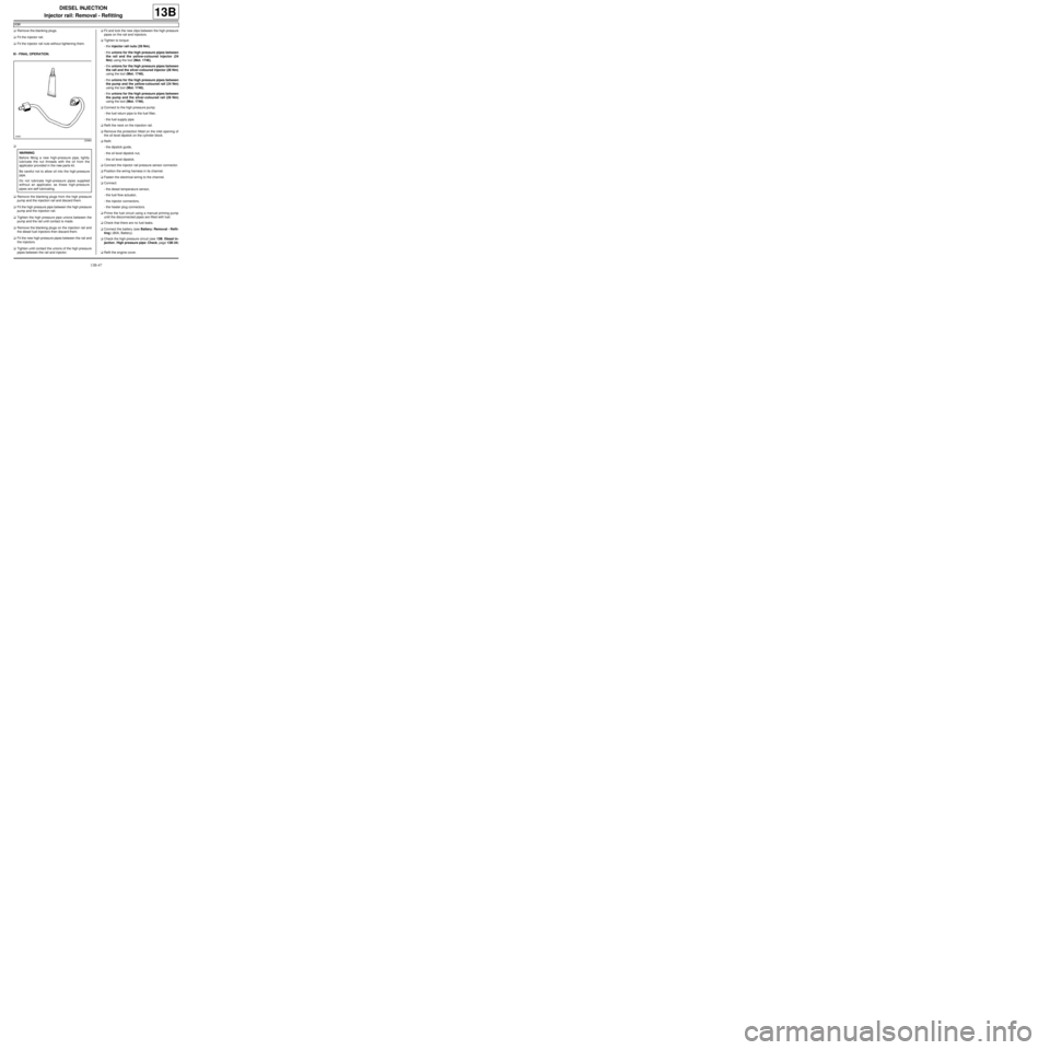
aRemove the blanking plugs from the high pressure
pump and the injection rail and discard them.
aFit the high pressure pipe between the high pressure
pump and the injection rail.
aTighten the high pressure pipe unions between the
pump and the rail until contact is made.
aRemove the blanking plugs on the injection rail and
the diesel fuel injectors then discard them.
aFit the new high-pressure pipes between the rail and
the injectors.
aTighten until contact the unions of the high pressure
pipes between the rail and injector.aFit and lock the new clips between the high pressure
pipes on the rail and injectors.
aTighten to torque:
-the injector rail nuts (28 Nm),
-the unions for the high pressure pipes between
the rail and the yellow-coloured injector (24
Nm) using the tool (Mot. 1746),
-the unions for the high pressure pipes between
the rail and the silver-coloured injector (28 Nm)
using the tool (Mot. 1746),
-the unions for the high pressure pipes between
the pump and the yellow-coloured rail (24 Nm)
using the tool (Mot. 1746),
-the unions for the high pressure pipes between
the pump and the silver-coloured rail (28 Nm)
using the tool (Mot. 1746),
aConnect to the high pressure pump:
-the fuel return pipe to the fuel filter,
-the fuel supply pipe.
aRefit the neck on the injection rail.
aRemove the protection fitted on the inlet opening of
the oil level dipstick on the cylinder block.
aRefit:
-the dipstick guide,
-the oil level dipstick nut,
-the oil level dipstick.
aConnect the injector rail pressure sensor connector.
aPosition the wiring harness in its channel.
aFasten the electrical wiring to the channel.
aConnect:
-the diesel temperature sensor,
-the fuel flow actuator,
-the injector connectors,
-the heater plug connectors.
aPrime the fuel circuit using a manual priming pump
until the disconnected pipes are filled with fuel.
aCheck that there are no fuel leaks.
aConnect the battery (see Battery: Removal - Refit-
ting) (80A, Battery).
aCheck the high pressure circuit (see 13B, Diesel in-
jection, High pressure pipe: Check, page 13B-34)
.
aRefit the engine cover.
20960
WARNING
Before fitting a new high-pressure pipe, lightly
lubricate the nut threads with the oil from the
applicator provided in the new parts kit.
Be careful not to allow oil into the high-pressure
pipe.
Do not lubricate high-pressure pipes supplied
without an applicator, as these high-pressure
pipes are self-lubricating.
Page 422 of 652
14A-4
ANTIPOLLUTION
Fuel vapour absorber: Removal - Refitting
D4F or D7F or K4M, and TECHNICAL REG: GERMANY or TECHNICAL REG: AUSTRIA or TECHNICAL REG:
BALKANS or TECHNICAL-LEGISLATIVE BELGIUM or TECHNICAL REG: BOSNIA or TECHNICAL REG:
CYPRUS-MALTA or CZECH REP AND SLOVAKIA or TECHNICAL REG: DENMARK or TECHNICAL REG: DOM
(FRENCH OVERSEAS SUBDIVISION) or TECHNICAL REG: SPAIN or TECHNICAL REG: FINLAND or
TECHNICAL REG: FRANCE or TECHNICAL REG: GREAT BRITAIN or TECHNICAL REG: GREECE or
TECHNICAL-LEGISLATIVE HOLLAND or TECHNICAL REG: HUNGARY or TECHNICAL REG: IRELAND or
TECHNICAL REG: ICELAND or TECHNICAL REG: ISRAEL or TECHNICAL REG: ITALY or TECHNICAL REG:
JAPAN or TECHNICAL REG: NORTH or TECHNICAL REG: NORWAY or TECHNICAL REG: POLAND or
TECHNICAL REG: PORTUGAL or TECHNICAL REG: SLOVENIA or TECHNICAL REG: SWEDEN or TECHNICAL
REG: SWITZERLAND or TECHNICAL REG: TOM (FRENCH OVERSEAS TERRITORIES)
14A
REMOVAL
I - REMOVAL PREPARATION OPERATION
aPosition the vehicle on a two-post lift (see Vehicle:
Towing and lifting) (02A, Lifting equipment).
aDisconnect the battery (see Battery: Removal - Re-
fitting) (80A, Battery).
II - REMOVAL OPERATION
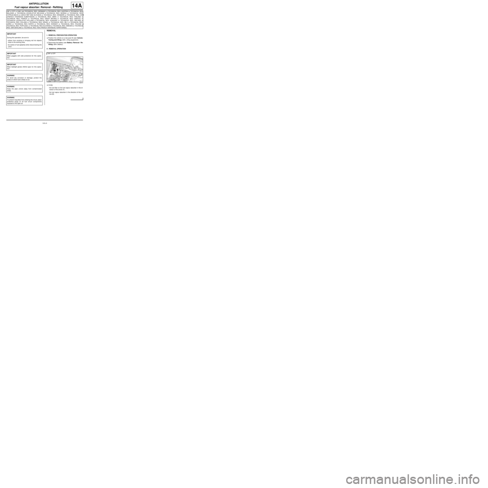
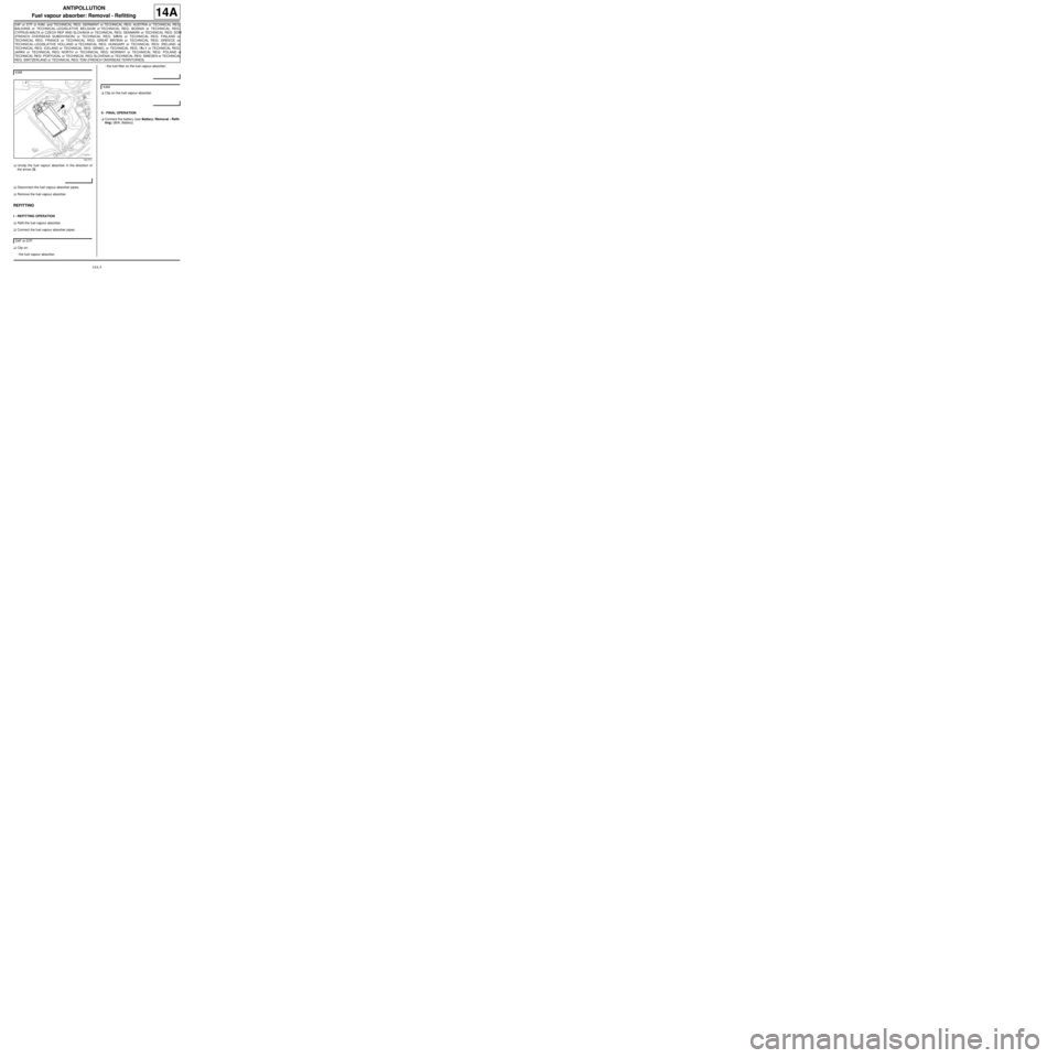
aUnclip:
-the fuel filter on the fuel vapour absorber in the di-
rection of the arrow (1) ,
-the fuel vapour absorber in the direction of the ar-
row (2) . IMPORTANT
During this oper ation, be sure to:
-refrain from smoking or bringing red hot objects
close to the working area,
-be careful of fuel splashes when disconnecting the
union.
IMPORTANT
Wear goggles with side protectors for this opera-
tion.
IMPORTANT
Wear leaktight gloves (Nitrile type) for this opera-
tion.
WARNING
To avoid any corrosion or damage, protect the
areas on which fuel is likely to run.
WARNING
Keep the pipe unions away from contaminated
areas.
WARNING
To prevent impurities from entering the circuit, place
protective plugs on all fuel circuit components
exposed to the open air.
D4F or D7F
120513
Page 423 of 652
14A-5
ANTIPOLLUTION
Fuel vapour absorber: Removal - Refitting
D4F or D7F or K4M, and TECHNICAL REG: GERMANY or TECHNICAL REG: AUSTRIA or TECHNICAL REG:
BALKANS or TECHNICAL-LEGISLATIVE BELGIUM or TECHNICAL REG: BOSNIA or TECHNICAL REG:
CYPRUS-MALTA or CZECH REP AND SLOVAKIA or TECHNICAL REG: DENMARK or TECHNICAL REG: DOM
(FRENCH OVERSEAS SUBDIVISION) or TECHNICAL REG: SPAIN or TECHNICAL REG: FINLAND or
TECHNICAL REG: FRANCE or TECHNICAL REG: GREAT BRITAIN or TECHNICAL REG: GREECE or
TECHNICAL-LEGISLATIVE HOLLAND or TECHNICAL REG: HUNGARY or TECHNICAL REG: IRELAND or
TECHNICAL REG: ICELAND or TECHNICAL REG: ISRAEL or TECHNICAL REG: ITALY or TECHNICAL REG:
JAPAN or TECHNICAL REG: NORTH or TECHNICAL REG: NORWAY or TECHNICAL REG: POLAND or
TECHNICAL REG: PORTUGAL or TECHNICAL REG: SLOVENIA or TECHNICAL REG: SWEDEN or TECHNICAL
REG: SWITZERLAND or TECHNICAL REG: TOM (FRENCH OVERSEAS TERRITORIES)
14A
aUnclip the fuel vapour absorber in the direction of
the arrow (3) .
aDisconnect the fuel vapour absorber pipes.
aRemove the fuel vapour absorber.
REFITTING
I - REFITTING OPERATION
aRefit the fuel vapour absorber.
aConnect the fuel vapour absorber pipes.
aClip on:
-the fuel vapour absorber,-the fuel filter on the fuel vapour absorber.
aClip on the fuel vapour absorber.
II - FINAL OPERATION
aConnect the battery (see Battery: Removal - Refit-
ting) (80A, Battery). K4M
131771
D4F or D7F
K4M
Page 428 of 652
14A-10
ANTIPOLLUTION
Exhaust gas recirculation solenoid valve: Removal - Refitting
K9K
14A
PARTS AND CONSUMABLES FOR THE
REPAIR WORK
aConsumables (see Vehicle: Parts and consuma-
bles for the repair) (02A, Parts and consumables):
-ABRASIVE PAD,
-SURFACE CLEANER.
REMOVAL
I - REMOVAL PREPARATION OPERATION
aRemove:
-the engine cover,
-the air filter box (see 12A, Fuel mixture, Air filter
unit: Removal - Refitting, page 12A-13) .
II - OPERATION FOR REMOVAL OF PART
CONCERNED
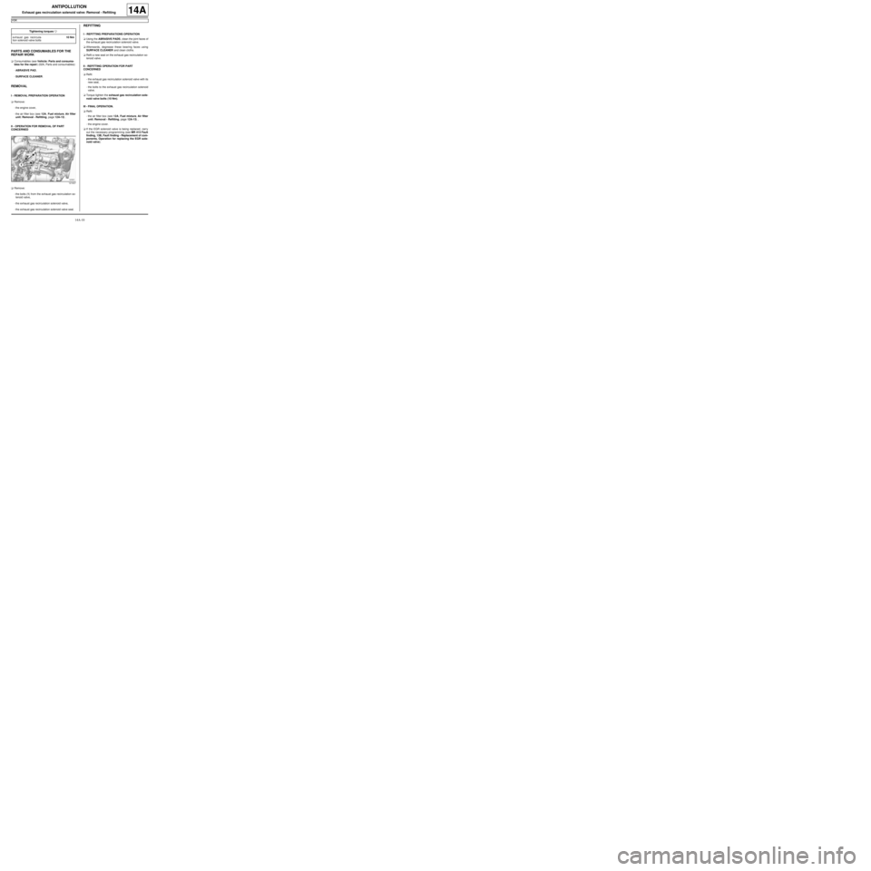
aRemove:
-the bolts (1) from the exhaust gas recirculation so-
lenoid valve,
-the exhaust gas recirculation solenoid valve,
-the exhaust gas recirculation solenoid valve seal.
REFITTING
I - REFITTING PREPARATIONS OPERATION
aUsing the ABRASIVE PADS, clean the joint faces of
the exhaust gas recirculation solenoid valve.
aAfterwards, degrease these bearing faces using
SURFACE CLEANER and clean cloths.
aRefit a new seal on the exhaust gas recirculation so-
lenoid valve.
II - REFITTING OPERATION FOR PART
CONCERNED
aRefit:
-the exhaust gas recirculation solenoid valve with its
new seal,
-the bolts to the exhaust gas recirculation solenoid
valve.
aTorque tighten the exhaust gas recirculation sole-
noid valve bolts (10 Nm).
III - FINAL OPERATION.
aRefit:
-the air filter box (see 12A, Fuel mixture, Air filter
unit: Removal - Refitting, page 12A-13) ,
-the engine cover.
aIf the EGR solenoid valve is being replaced, carry
out the necessary programming (see MR 413 Fault
finding, 13B, Fault finding - Replacement of com-
ponents, Operation for replacing the EGR sole-
noid valve). Tightening torquesm
exhaust gas recircula-
tion solenoid valve bolts10 Nm
121637
Page 429 of 652
14A-11
ANTIPOLLUTION
Exhaust gas cooler: Removal - Refitting
K9K
14A
REMOVAL
I - REMOVAL PREPARATION OPERATION
aPosition the vehicle on a two-post lift (see Vehicle:
Towing and lifting) (02A, Lifting equipment).
aDisconnect the battery (see ) (80A, Battery).
aRemove:
-the engine cover,
-the windscreen wiper arms (see Windscreen wip-
er arm: Removal - Refitting) (85A, Wiping -
Washing),
-the scuttle panel grille (see Scuttle panel grille:
Removal - Refitting) (56A, Exterior equipment),
-the scoop under the scuttle panel grille (see Scoop
under the scuttle panel grille: Removal - Refit-
ting) (56A, Exterior equipment),
-the air filter unit (see 12A, Fuel mixture, Air filter
unit: Removal - Refitting, page 12A-13) ,
-the EGR solenoid valve (see 14A, Antipollution,
Exhaust gas recirculation solenoid valve: Re-
moval - Refitting, page 14A-10) ,
-the lower engine tie-bar (see 19D, Engine mount-
ing, Lower engine tie-bar: Removal - Refitting,
page 19D-18) ,
-the catalytic converter (see 19B, Exhaust, Cata-
lytic converter: Removal - Refitting, page 19B-
12) ,-the exhaust gas recirculation rigid pipe (see 14A,
Antipollution, Exhaust gas recirculation rigid
pipe: Removal - Refitting, page 14A-19) ,
-the exhaust gas recirculation assembly (see 14A,
Antipollution, Exhaust gas recirculation as-
sembly: Removal - Refitting, page 14A-15) .
II - OPERATION FOR REMOVAL OF PART
CONCERNED
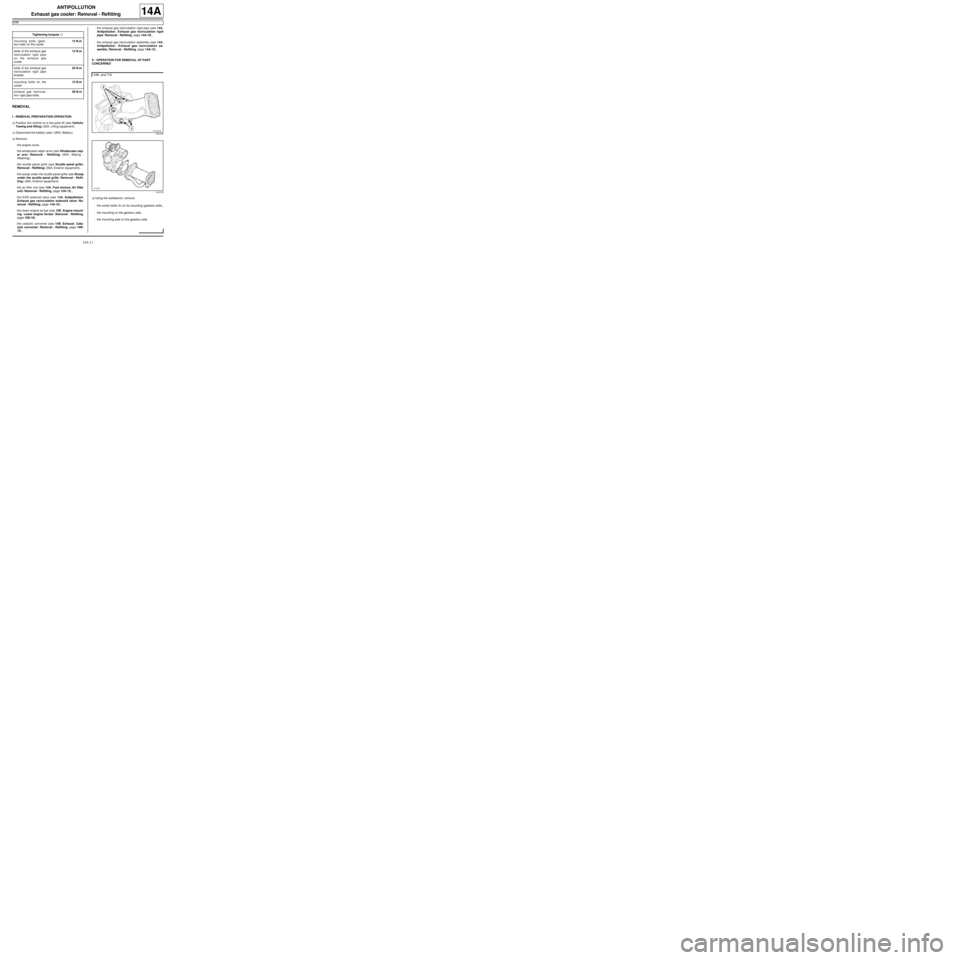
aUsing the workbench, remove:
-the cooler bolts (1) on its mounting (gearbox side),
-the mounting on the gearbox side,
-the mounting seal on the gearbox side. Tightening torquesm
mounting bolts (gear-
box side) on the cooler12 N.m
bolts of the exhaust gas
recirculation rigid pipe
on the exhaust gas
cooler12 N.m
bolts of the exhaust gas
recirculation rigid pipe
bracket25 N.m
mounting bolts on the
cooler12 N.m
exhaust gas recircula-
tion r igid pipe bolts36 N.m
K9K, and 718
141215
141216
Page 432 of 652
14A-14
ANTIPOLLUTION
Exhaust gas cooler: Removal - Refitting
K9K
14A
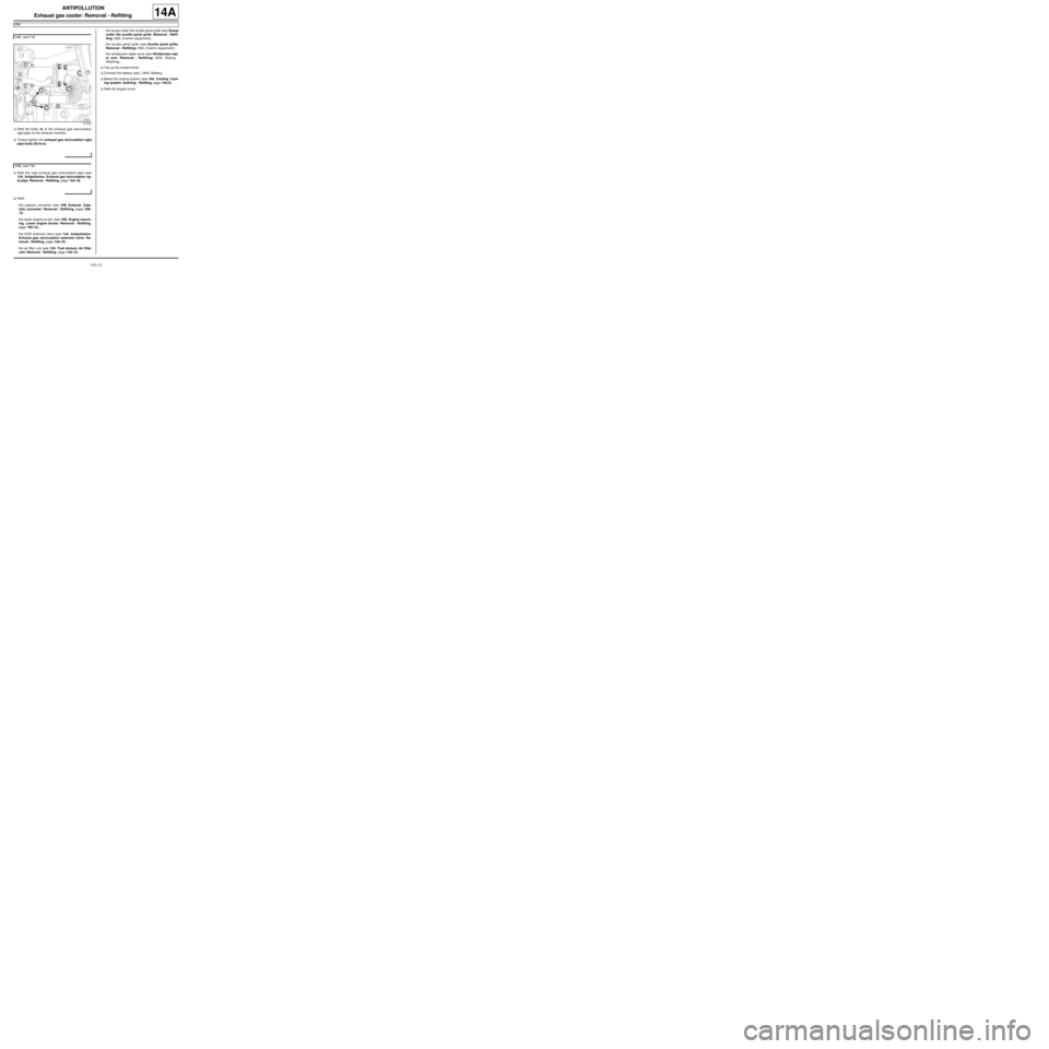
aRefit the bolts (4) of the exhaust gas recirculation
rigid pipe on the exhaust manifold.
aTorque tighten the exhaust gas recirculation rigid
pipe bolts (36 N.m).
aRefit the rigid exhaust gas recirculation pipe (see
14A, Antipollution, Exhaust gas recirculation rig-
id pipe: Removal - Refitting, page 14A-19) .
aRefit:
-the catalytic converter (see 19B, Exhaust, Cata-
lytic converter: Removal - Refitting, page 19B-
12) ,
-the lower engine tie-bar (see 19D, Engine mount-
ing, Lower engine tie-bar: Removal - Refitting,
page 19D-18) ,
-the EGR solenoid valve (see 14A, Antipollution,
Exhaust gas recirculation solenoid valve: Re-
moval - Refitting, page 14A-10) ,
-the air filter unit (see 12A, Fuel mixture, Air filter
unit: Removal - Refitting, page 12A-13) ,-the scoop under the scuttle panel grille (see Scoop
under the scuttle panel grille: Removal - Refit-
ting) (56A, Exterior equipment),
-the scuttle panel grille (see Scuttle panel grille:
Removal - Refitting) (56A, Exterior equipment),
-the windscreen wiper arms (see Windscreen wip-
er arm: Removal - Refitting) (85A, Wiping -
Washing),
aTop up the coolant level.
aConnect the battery (see ) (80A, Battery).
aBleed the cooling system (see 19A, Cooling, Cool-
ing system: Draining - Refilling, page 19A-9) .
aRefit the engine cover. K9K, and 718
141224
K9K, and 740
Page 433 of 652
14A-15
ANTIPOLLUTION
Exhaust gas recirculation assembly: Removal - Refitting
K9K
14A
REMOVAL
I - REMOVAL PREPARATION OPERATION
aPosition the vehicle on a two-post lift (see Vehicle:
Towing and lifting) (02A, Lifting equipment).
aDisconnect the battery (see ) (80A, Battery).
aRemove:
-the engine cover,
-the windscreen wiper arms (see Windscreen wip-
er arm: Removal - Refitting) (85A, Wiping -
Washing)
-the scuttle panel grille (see Scuttle panel grille:
Removal - Refitting) (56A, Exterior equipment),
-the scoop under the scuttle panel grille (see Scoop
under the scuttle panel grille: Removal - Refit-
ting) (56A, Exterior equipment),
-the air filter unit (see 12A, Fuel mixture, Air filter
unit: Removal - Refitting, page 12A-13) ,
-the EGR solenoid valve (see 14A, Antipollution,
Exhaust gas recirculation solenoid valve: Re-
moval - Refitting, page 14A-10) ,
-the lower engine tie-bar (see 19D, Engine mount-
ing, Lower engine tie-bar: Removal - Refitting,
page 19D-18) ,
-the catalytic converter (see 19B, Exhaust, Cata-
lytic converter: Removal - Refitting, page 19B-
12) ,
-the rigid exhaust gas recirculation pipe (see 14A,
Antipollution, Exhaust gas recirculation rigid
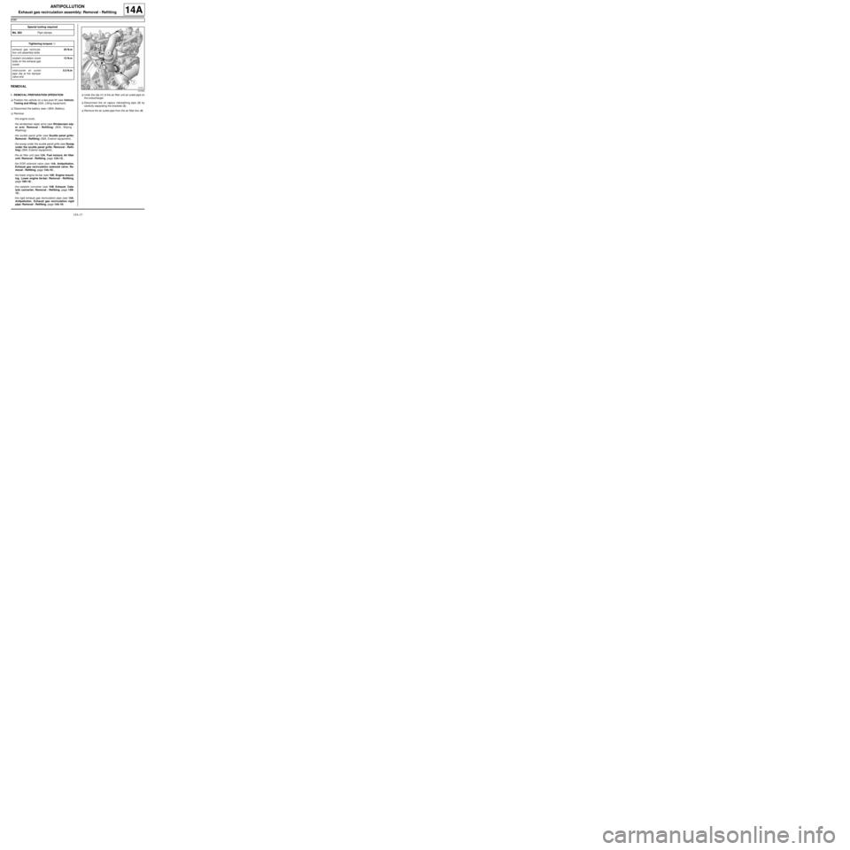
pipe: Removal - Refitting, page 14A-19) .aUndo the clip (1) of the air filter unit air outlet pipe on
the turbocharger.
aDisconnect the oil vapour rebreathing pipe (2) by
carefully separating the brackets (3) .
aRemove the air outlet pipe from the air filter box (4) . Special tooling required
Ms. 583Pipe clamps .
Tightening torquesm
exhaust gas recircula-
tion unit assembly bolts25 N.m
coolant circulation cover
bolts on the exhaust gas
cooler12 N.m
intercooler air outlet
pipe clip at the damper
valve end5.5 N.m
121633
Page 436 of 652
14A-18
ANTIPOLLUTION
Exhaust gas recirculation assembly: Removal - Refitting
K9K
14A
aRefit:
-new seals on the coolant circulation cover,
-the coolant circulation cover on the exhaust gas
cooler.
aTorque tighten the coolant circulation cover bolts
on the exhaust gas cooler (12 N.m).
aRemove the tool (Ms. 583) from the coolant inlet and
outlet hoses of the exhaust gas cooler.
III - FINAL OPERATION
aFit the intercooler air outlet pipe at the damper valve
end.
aConnect the intercooler air outlet pipe on the side of
the damper valve.
aTorque tighten the intercooler air outlet pipe clip
at the damper valve end (5.5 N.m).
aRefit the intercooler air outlet pipe nut on the lifting
eye.
aConnect the turbocharging pressure regulator vacu-
um pipe.
aClip:
-the turbocharging pressure regulator vacuum pipe,
-the vacuum pipe from the brake servo.
aConnect the brake servo vacuum pipe.
aFit the intercooler air inlet pipe at the turbocharger
end.
aRefit the intercooler air inlet pipe nut at the turbo-
charger end on the lifting eye.
aConnect the intercooler air inlet pipe at the turbo-
charger end.
aClip on the intercooler air inlet pipe clip at the turbo-
charger end.
aRefit the air outlet pipe onto the air filter unit.
aTighten the air filter unit air outlet pipe clip on the tur-
bocharger.
aConnect the oil vapour rebreathing pipe.
aRefit:
-the exhaust gas recirculation rigid pipe (see 14A,
Antipollution, Exhaust gas recirculation rigid
pipe: Removal - Refitting, page 14A-19) ,-the catalytic converter (see 19B, Exhaust, Cata-
lytic converter: Removal - Refitting, page 19B-
12) ,
-the lower engine tie-bar (see 19D, Engine mount-
ing, Lower engine tie-bar: Removal - Refitting,
page 19D-18) ,
-the EGR solenoid valve (see 14A, Antipollution,
Exhaust gas recirculation solenoid valve: Re-
moval - Refitting, page 14A-10) ,
-the air filter unit (see 12A, Fuel mixture, Air filter
unit: Removal - Refitting, page 12A-13) ,
-the scoop under the scuttle panel grille (see Scoop
under the scuttle panel grille: Removal - Refit-
ting) (56A, Exterior equipment).
-the scuttle panel grille (see Scuttle panel grille:
Removal - Refitting) (56A, Exterior equipment),
-the windscreen wiper arms (see Windscreen wip-
er arm: Removal - Refitting) (85A, Wiping -
Washing),
aConnect the battery (see ) (80A, Battery).
aFill and bleed the cooling system (see 19A, Cool-
ing, Cooling system: Draining - Refilling, page
19A-9) .
aRefit the engine cover. K9K, and 718