RENAULT TWINGO 2009 2.G Engine And Peripherals Workshop Manual
TWINGO 2009 2.G
RENAULT
RENAULT
https://www.carmanualsonline.info/img/7/1710/w960_1710-0.png
RENAULT TWINGO 2009 2.G Engine And Peripherals Workshop Manual
Page 415 of 652
13B-54
DIESEL INJECTION
Accelerometer: Removal - Refitting
K9K
13B
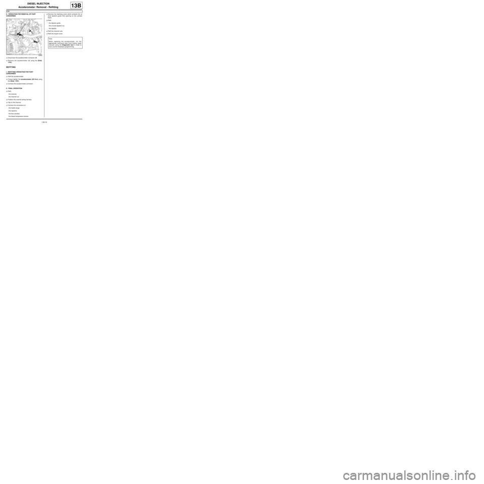
II - OPERATION FOR REMOVAL OF PART
CONCERNED
aDisconnect the accelerometer connector (4) .
aRemove the accelerometer (4) using the (Emb.
1797).
REFITTING
I - REFITTING OPERATION FOR PART
CONCERNED
aRefit the accelerometer.
aTorque tighten the accelerometer (20 N.m) using
the (Emb. 1797).
aConnect the accelerometer connector.
II - FINAL OPERATION
aRefit:
-the channel,
-the channel nut.
aPosition the channel wiring harness.
aClip on the channel.
aConnect the connectors of:
-the heater plugs,
-the injectors,
-the flow actuator,
-the diesel temperature sensor.aRemove the blanking cover which protects the oil
level dipstick guide inlet opening on the cylinder
block.
aRefit:
-the dipstick guide,
-the oil level dipstick nut,
-the dipstick.
aRefit the channel nuts.
aRefit the engine cover.
109939
Note:
When replacing the accelerometer, run the
appropriate command (see Fault finding repair
manual) using the Diagnostic tool in order to
carr y out the necessary programming.
Page 449 of 652
16A-10
STARTING - CHARGING
Starter: Removal - Refitting
D4F or D7F
16A
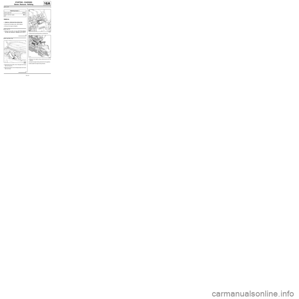
REMOVAL
I - REMOVAL PREPARATION OPERATION
aDisconnect the battery (see ) (80A, Battery).
aRemove the engine oil dipstick.
aRemove the air filter unit (see 12A, Fuel mixture,
Air filter unit: Removal - Refitting, page 12A-13) .
aDisconnect the air filter unit air inlet pipe from the air
filter unit cover (1) .
aMove the air filter unit air inlet pipe away from the air
filter unit cover.aDisconnect the pinking sensor connector (2) .
aRemove the engine wiring channel bolt from the
gearbox.
aUnclip the engine wiring channel from the gearbox.
aMove aside the engine wiring channel. Tightening torquesm
starter upper bolt44 N.m
starter electrical supply
nut8N.m
D4F, and 772
D4F, and 780 or 782
122833
120512
120414
Page 452 of 652
16A-13
STARTING - CHARGING
Starter: Removal - Refitting
D4F or D7F
16A
aClip the engine wiring channel onto the gearbox.
aRefit the engine wiring channel bolt to the gearbox.
aTighten the engine wiring channel bolt on the gear-
box.
aConnect the pinking sensor connector.
aFit the air filter unit air inlet pipe on the air filter unit
cover.
aConnect the air filter unit air inlet pipe on the air filter
unit cover.
aRefit the air filter unit (see 12A, Fuel mixture, Air fil-
ter unit: Removal - Refitting, page 12A-13) .
aRefit the engine oil dipstick.
aConnect the battery (see ) (80A, Battery). D4F, and 780 or 782
D4F, and 772
Page 453 of 652
16A-14
STARTING - CHARGING
Starter: Removal - Refitting
K9K
16A
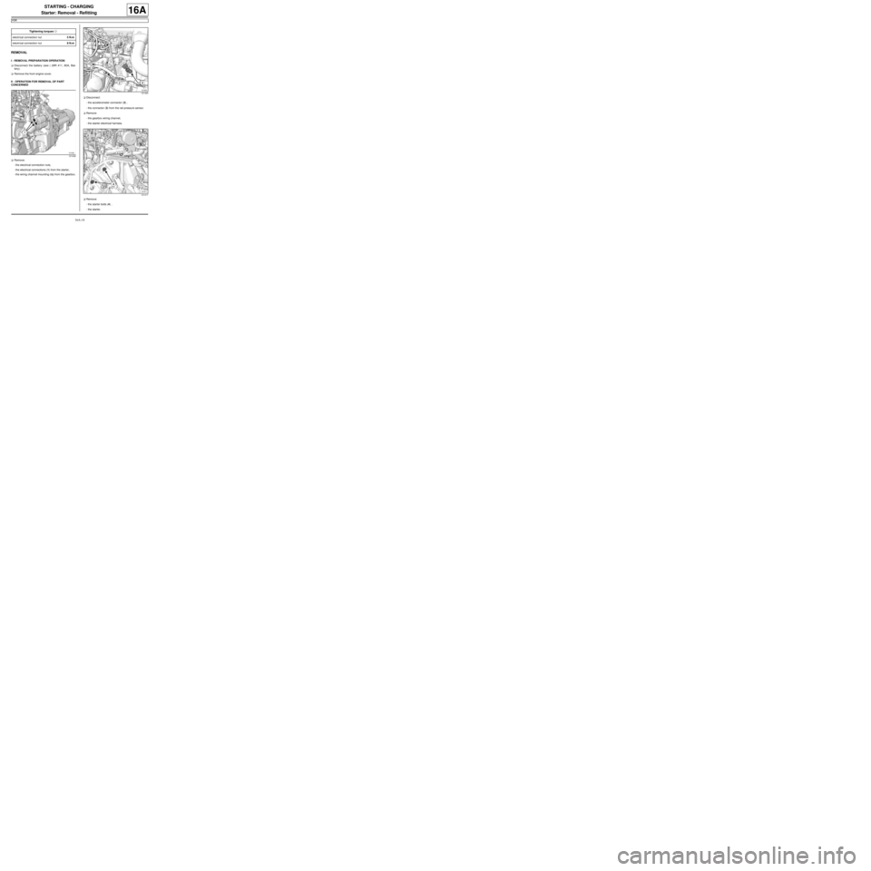
REMOVAL
I - REMOVAL PREPARATION OPERATION
aDisconnect the battery (see ) (MR 411, 80A, Bat-
tery).
aRemove the front engine cover.
II - OPERATION FOR REMOVAL OF PART
CONCERNED
aRemove:
-the electrical connection nuts,
-the electrical connections (1) from the starter,
-the wiring channel mounting clip from the gearbox.aDisconnect:
-the accelerometer connector (2) ,
-the connector (3) from the rail pressure sensor.
aRemove:
-the gearbox wiring channel,
-the starter electrical harness.
aRemove:
-the starter bolts (4) ,
-the starter. Tightening torquesm
electr ical connection nut5 N.m
electr ical connection nut8 N.m
121432
121420
121417
Page 454 of 652
16A-15
STARTING - CHARGING
Starter: Removal - Refitting
K9K
16A
REFITTING
I - REFITTING OPERATION FOR PART
CONCERNED
aRefit:
-the starter,
-the starter bolts.
aTighten the starter bolts.
aFit:
-the starter wiring harness,
-the gearbox wiring channel.
aRefit:
-the wiring channel mounting clip on the gearbox,
-the electrical connections on the starter,
-the electrical connection nuts.
aTighten to torque:
-the electrical connection nut (5 N.m) (5) ,
-the electrical connection nut (8 N.m) (6) .
aConnect:
-the accelerometer connector,
-the rail pressure sensor connector.
II - FINAL OPERATION
aRefit the engine cover.
aConnect the battery (see ) (MR 411, 80A, Battery).
121432
Page 476 of 652
17B-1
PETROL INJECTION
Petrol injection: List and location of components
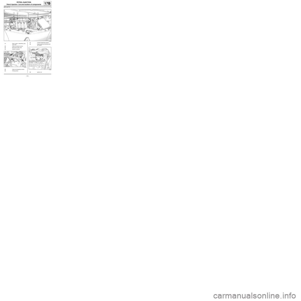
D4F, and 772
17B
121740
(1) Petrol vapour rebreathing sole-
noid valve
(2) Intake air pressure sensor
(3) Motorised throttle valve
(4) Injection computer
121739
(5) Intake air temperature sensor
(6) Pinking sensor
(7) Coolant temper ature sensor
(8) Engine speed and flywheel posi-
tion sensor
113044
(9) Ignition coil
Page 477 of 652
17B-2
PETROL INJECTION
Petrol injection: List and location of components
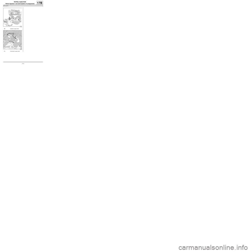
D4F, and 772
17B
121732
(10) Upstream oxygen sensor
120415
(11) Downstream oxygen sensor
Page 478 of 652
17B-3
PETROL INJECTION
Petrol injection: List and location of components
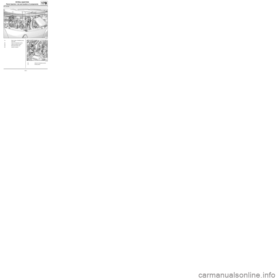
D7F, and 800
17B
121741
(1) Petrol vapour rebreathing sole-
noid valve
(2) Intake air temperature sensor
(3) Intake air pressure sensor
(4) Motorised throttle valve
(5) Injection computer
121738
(6) Intake air temperature sensor
(7) Pinking sensor
Page 479 of 652
17B-4
PETROL INJECTION
Petrol injection: List and location of components
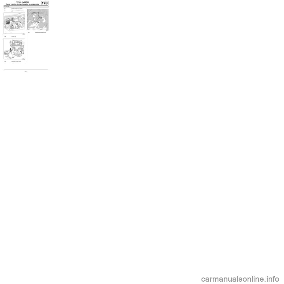
D7F, and 800
17B
(8) Coolant temper ature sensor
(9) Engine speed and position sen-
sor
120404
(10) Ignition coil
121732
(11) Upstream oxygen sensor
120415
(12) Downstream oxygen sensor
Page 480 of 652
17B-5
PETROL INJECTION
Petrol injection: List and location of components
D4F, and 780 or 782
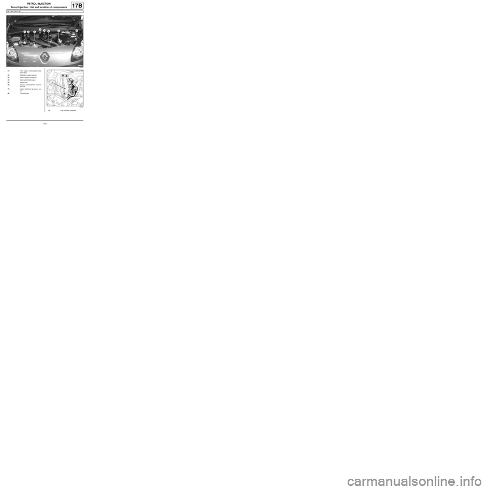
17B
122387
(1) Fuel vapour recirculation sole-
noid valve
(2) Upstream oxygen sensor
(3) Petrol injection computer
(4) Motorised throttle valve
(5) Ignition coil
(6) Engine compar tment connec-
tion unit
(7) Intake distributor pressure sen-
sor
(8) Turbocharger
108254
(9) Fuel injection computer

