engine RENAULT TWINGO 2009 2.G Engine And Peripherals Workshop Manual
[x] Cancel search | Manufacturer: RENAULT, Model Year: 2009, Model line: TWINGO, Model: RENAULT TWINGO 2009 2.GPages: 652
Page 142 of 652
11A-25
TOP AND FRONT OF ENGINE
Crankshaft accessories pulley: Removal - Refitting
K4M
11A
REMOVAL
I - REMOVAL PREPARATION OPERATION
aPosition the vehicle on a two-post lift (see Vehicle:
Towing and lifting) (02A, Lifting equipment).
aDisconnect the battery (see Battery: Removal - Re-
fitting) (80A, Battery).
aRemove:
-the front right-hand wheel (see Wheel: Removal -
Refitting) (35A, Wheels and tyres),
-the engine undertray,
-the front right-hand wheel arch liner (see Front
wheel arch liner: Removal - Refitting) (55A, Ex-
terior protection),
-the front bumper (see Front bumper: Removal -
Refitting) (55A, Exterior protection),
-the headlights (see Halogen headlight: Removal
- Refitting) (80B, Headlights),
-the bonnet catch (see Bonnet lock: Removal -
Refitting) (52A, Non-side opening element mecha-
nisms),
-the front upper cross member (see Front upper
cross member: Removal - Refitting) (42A, Upper
front structure),
-the accessories belt (see 11A, Top and front of
engine, Accessories belt: Removal - Refitting,
page 11A-3) .II - REMOVAL OPERATION
aRemove:
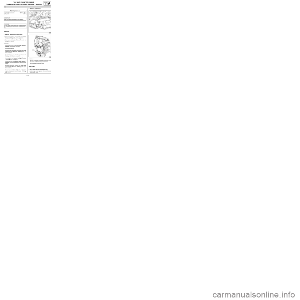
-the bolt (1) from the crankshaft accessories pulley
by locking the flywheel using a screwdriver,
-the crankshaft accessories pulley.
REFITTING
I - REFITTING PREPARATION OPERATION
aparts always to be replaced: Crankshaft acces-
sories pulley bolts. Tightening torquesm
crankshaft accessories
pulley bolts120 N.m + 95˚
±± ± ±
10˚
IMPORTANT
Wear cut-resistant gloves during the operation.
WARNING
Do not r un the engine without the accessories belt
to avoid damaging the crankshaft accessories pul-
ley.
133106
14487
Page 143 of 652
11A-26
TOP AND FRONT OF ENGINE
Crankshaft accessories pulley: Removal - Refitting
K4M
11A
aUse a brush to remove any deposits from the crank-
shaft accessories pulley V grooves.
II - REFITTING OPERATION
aRefit the crankshaft accessories pulley.
aTighten to torque and angle the crankshaft acces-
sories pulley bolts (120 N.m + 95˚ ±± ± ±
10˚) by locking
the engine flywheel using a flat-blade screwdriver.
III - FINAL OPERATION
aRefit:
-the accessories belt (see 11A, Top and front of
engine, Accessories belt: Removal - Refitting,
page 11A-3) .
-the front upper cross member (see Front upper
cross member: Removal - Refitting) (42A, Upper
front structure),
-the bonnet catch (see Bonnet lock: Removal -
Refitting) (52A, Non-side opening element mecha-
nisms),
-the headlights (see Halogen headlight: Removal
- Refitting) (80B, Headlights),
-the front bumper (see Front bumper: Removal -
Refitting) (55A, Exterior protection),
-the front right-hand wheel arch liner (see Front
wheel arch liner: Removal - Refitting) (55A, Ex-
terior protection),
-the engine undertray,
-the front right-hand wheel (see Wheel: Removal -
Refitting) (35A, Wheels and tyres).
aConnect the battery (see Battery: Removal - Refit-
ting) (80A, Battery).
Page 144 of 652
11A-27
TOP AND FRONT OF ENGINE
Timing belt: Removal - Refitting
D7F, and 800
11A
PARTS AND CONSUMABLES FOR THE
REPAIR WORK
aParts always to be replaced:
-the timing belt,
-the tensioning roller,
-the accessories pulley bolt.
REMOVAL
I - REMOVAL PREPARATION OPERATION
aPosition the vehicle on a two-post lift (see Vehicle:
Towing and lifting) .
aDisconnect the battery ( (see Battery: Removal -
Refitting) ).
aRemove:
-the front right-hand wheel arch liner (see) (see ) ,
-the front right-hand wheel ( (see Wheel: Removal
- Refitting) ),
-the accessories belt (see 11A, Top and front of
engine, Accessories belt: Removal - Refitting,
page 11A-3) ,-the accessories pulley (see 11A, Top and front of
engine, Crankshaft accessories pulley: Remov-
al - Refitting, page 11A-20) ,
-the rear suspended engine mounting (see 19D,
Engine mounting, Lower engine tie-bar: Re-
moval - Refitting, page 19D-18) .
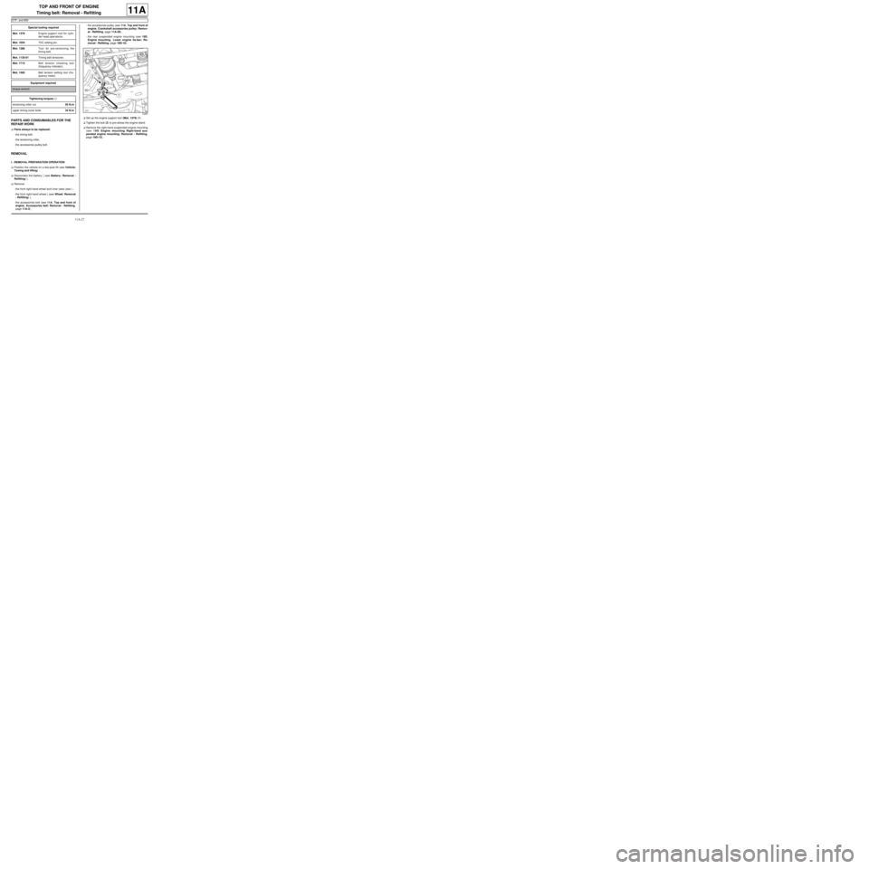
aSet up the engine support tool (Mot. 1379) (1) .
aTighten the bolt (2) to pre-stress the engine stand.
aRemove the right-hand suspended engine mounting
(see 19D, Engine mounting, Right-hand sus-
pended engine mounting: Removal - Refitting,
page 19D-13) . Special tooling required
Mot. 1379Engine suppor t tool for cylin-
der head oper ations.
Mot. 1054TDC setting pin.
Mot. 1386Tool for pre-tensioning the
timing belt.
Mot. 1135-01Timing belt tensioner.
Mot. 1715Belt tension checking tool
(frequency indicator).
Mot. 1505Belt tension setting tool (fre-
quency meter)
Equipment required
torque wrench
Tightening torquesm
tensioning roller nut50 N.m
upper timing cover bolts33 N.m
10267
Page 145 of 652
11A-28
TOP AND FRONT OF ENGINE
Timing belt: Removal - Refitting
D7F, and 800
11A
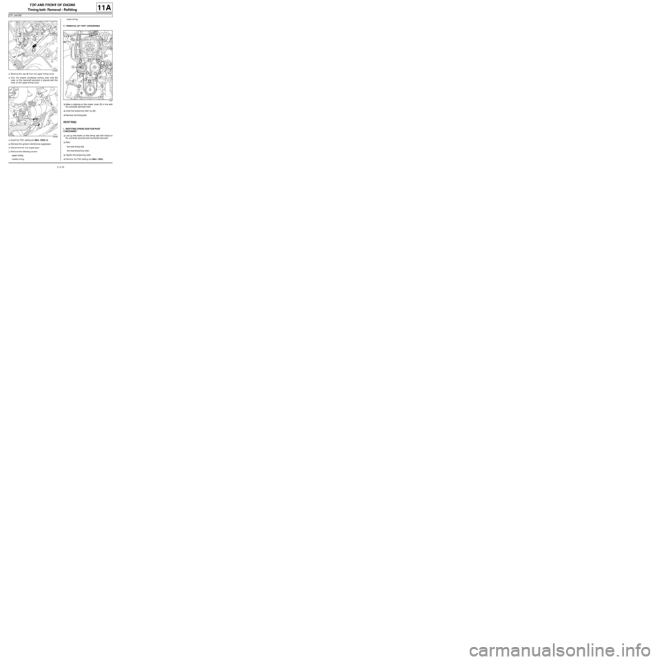
aRemove the cap (3) from the upper timing cover.
aTurn the engine clockwise (timing end) until the
mark on the camshaft sprocket is aligned with the
mark on the upper timing cover.
aInsert the TDC setting pin (Mot. 1054) (4)
aRemove the ignition interference suppressor.
aDisconnect the fuel supply pipe.
aRemove the following covers:
-upper timing,
-middle timing,-lower timing.
II - REMOVAL OF PART CONCERNED
aMake a marking on the rocker cover (5) in line with
the camshaft sprocket mark
aUndo the tensioning roller nut (6) .
aRemove the timing belt.
REFITTING
I - REFITTING OPERATION FOR PART
CONCERNED
aLine up the marks on the timing belt with those on
the camshaft sprocket and crankshaft sprocket.
aRefit:
-the new timing belt,
-the new tensioning roller.
aTighten the tensioning roller.
aRemove the TDC setting rod (Mot. 1054).
107259
99795
1041
Page 146 of 652
11A-29
TOP AND FRONT OF ENGINE
Timing belt: Removal - Refitting
D7F, and 800
11A
aPosition the spacer (7) of the timing belt pre-tension-
ing tool (Mot. 1386).
aPosition the timing belt tensioner (Mot. 1135-01) at
(8) on the tensioning roller.
aTurn the tensioning roller anti-clockwise until a belt
tension of 139 ±± ± ±
3 Hz is obtained with frequency
meter (Mot. 1715) (9) or (Mot. 1505).
aTighten the tensioning roller nut.aPosition the (Mot. 1386) (10) .
aApply a pretensioning torque to the timing belt sec-
tion (11) using a torque wrench set to 10 Nm.
aMake sure that the timing belt tension is 139 ±± ± ±
3 Hz
using the frequency meter (Mot. 1715) or (Mot.
1505) : otherwise, adjust it using the (Mot. 1135-01).
aTorque tighten the tensioning roller nut (50 N.m).
aTurn the crankshaft through four revolutions.
aSet the timing using the TDC setting pin (Mot. 1054).
aApply a pretensioning torque to the timing belt sec-
tion (11) using a torque wrench set to 10 Nm.
aMake sure that the timing belt tension is 139 ±± ± ±
3 Hz
using the frequency meter (Mot. 1715) or (Mot.
1505) : otherwise, adjust it using the (Mot. 1135-01).
II - FINAL OPERATION
aRefit the timing covers.
aTorque tighten clockwise the upper timing cover
bolts (33 N.m).
aRefit:
-the right-hand suspended engine mounting (see
19D, Engine mounting, Right-hand suspended
engine mounting: Removal - Refitting, page
19D-13) ,
-the accessories pulley (see 11A, Top and front of
engine, Crankshaft accessories pulley: Remov-
al - Refitting, page 11A-20) ,
10881
1629410881
Page 147 of 652
11A-30
TOP AND FRONT OF ENGINE
Timing belt: Removal - Refitting
D7F, and 800
11A
-the accessories belt (see 11A, Top and front of
engine, Accessories belt: Removal - Refitting,
page 11A-3) ,
-the front right-hand wheel arch liner (see MR 412
Bodywork, 55A, Exterior protection, Front
wheel arch liner: Removal-Refitting),
-the front right-hand wheel ( (see Wheel: Removal
- Refitting) .
aConnect the battery ( (see Battery: Removal - Re-
fitting) .
Page 148 of 652
11A-31
TOP AND FRONT OF ENGINE
Timing belt: Removal - Refitting
D4F
11A
REMOVAL
I - REMOVAL PREPARATION OPERATION
aPosition the vehicle on a two-post lift (see Vehicle:
Towing and lifting) (02A, Lifting equipment).
aDisconnect the battery (see ) (80A, Battery).
aRemove:
-the front right-hand wheel (see Wheel: Removal -
Refitting) (35A, Wheels and tyres),
-the front right-hand wheel arch liner (see Front
wheel arch liner: Removal - Refitting) (55A, Ex-
terior protection),
-the accessories belt (see 11A, Top and front of
engine, Accessories belt: Removal - Refitting,
page 11A-3) ,
-the rear suspended engine mounting (see 19D,
Engine mounting, Lower engine tie-bar: Re-
moval - Refitting, page 19D-18) .aSet up the engine support tool (Mot. 1379), shifting
the engine forwards.
aLift the engine slightly using the (Mot. 1379).
aRemove:
-the right-hand suspended engine mounting (see
19D, Engine mounting, Right-hand suspended
engine mounting: Removal - Refitting, page
19D-13) ,
-the crankshaft accessories pulley (see 11A, Top
and front of engine, Crankshaft accessories
pulley: Removal - Refitting, page 11A-20) .
aRefit the crankshaft accessories pulley bolt.
aUnclip the fuel pipe from the upper timing cover. Special tooling required
Mot. 1379Engine suppor t tool for cylin-
der head oper ations.
Mot. 1054TDC setting pin.
Tightening torquesm
tensioning roller nut24 N.m
lower timing cover bolt10 N.m
intermediate timing
cover bolts10 N.m
upper timing cover bolts37 N.m
10267
Page 149 of 652
11A-32
TOP AND FRONT OF ENGINE
Timing belt: Removal - Refitting
D4F
11A
aMove the flexible heat shield away from the oil pres-
sure sensor connector.
aDisconnect the oil pressure sensor connector (1) .
aUnclip the oil pressure sensor wiring from the upper
timing cover.
aMove the oil pressure sensor connector to one side.aRemove:
-the bolts (1) from the upper timing cover,
-the upper timing cover.
aRemove:
-the intermediate timing cover bolts (2) ,
-the timing intermediate housing,
-the lower timing cover bolt (3) ,
-the lower timing cover. D4F, and 780 or 782
122664
109740
109739
Page 150 of 652
11A-33
TOP AND FRONT OF ENGINE
Timing belt: Removal - Refitting
D4F
11A
II - OPERATION FOR REMOVAL OF PART
CONCERNED
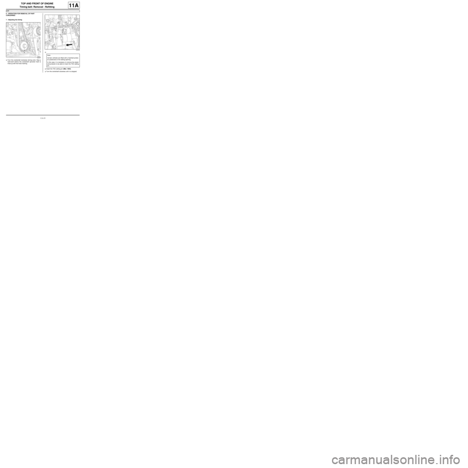
1 - Adjusting the timing
aTurn the crankshaft clockwise (timing end). Stop a
half-tooth before the crankshaft sprocket mark is
lined up with the fixed marking.a
aInsert the TDC setting pin (Mot. 1054).
aTurn the crankshaft clockwise until it is stopped.
109737
109735
Note:
Cer tain vehicles are fitted with a flywheel protec-
tor positioned on the setting opening.
In this case, it is necessar y to remove the starter
and protector to be able to insert the TDC setting
pin.
Page 151 of 652
11A-34
TOP AND FRONT OF ENGINE
Timing belt: Removal - Refitting
D4F
11A
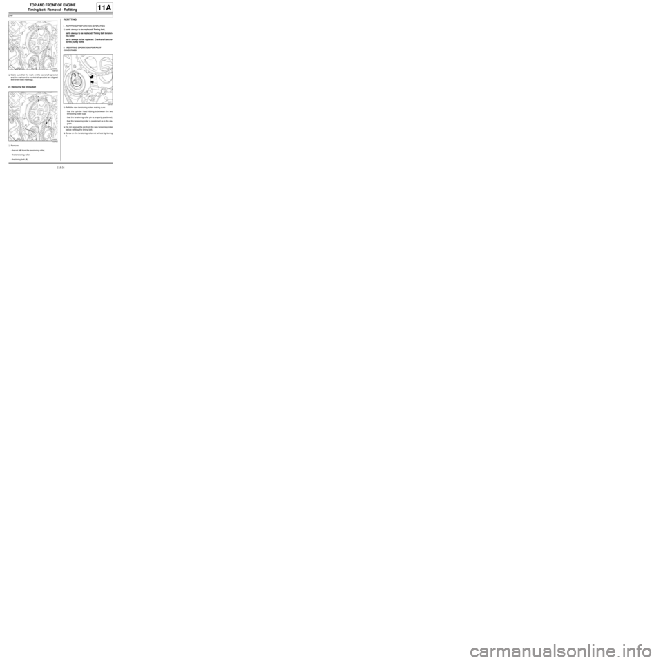
aMake sure that the mark on the camshaft sprocket
and the mark on the crankshaft sprocket are aligned
with their fixed markings.
2 - Removing the timing belt
aRemove:
-the nut (4) from the tensioning roller,
-the tensioning roller,
-the timing belt (5) .
REFITTING
I - REFITTING PREPARATION OPERATION
aparts always to be replaced: Timing belt,
parts always to be replaced: Timing belt tension-
ing roller,
parts always to be replaced: Crankshaft acces-
sories pulley bolts.
II - REFITTING OPERATION FOR PART
CONCERNED
aRefit the new tensioning roller, making sure:
-that the cylinder head ribbing is between the two
tensioning roller lugs,
-that the tensioning roller pin is properly positioned,
-that the tensioning roller is positioned as in the dia-
gram.
aDo not remove the pin from the new tensioning roller
before refitting the timing belt.
aScrew on the tensioning roller nut without tightening
it.
109738
109738
109761