fuel RENAULT TWINGO 2009 2.G Engine And Peripherals Workshop Manual
[x] Cancel search | Manufacturer: RENAULT, Model Year: 2009, Model line: TWINGO, Model: RENAULT TWINGO 2009 2.GPages: 652
Page 598 of 652
19B-16
EXHAUST
Catalytic converter: Removal - Refitting
D4F, and 780 or 782
19B
REMOVAL
I - REMOVAL PREPARATION OPERATION
aPosition the vehicle on a two-post lift (see Vehicle:
Towing and lifting) (MR 411, 02A, Lifting equip-
ment).
aDisconnect the battery (see Battery: Removal - Re-
fitting) (MR 411, 80A, Battery).
aRemove:
-the air filter unit (see 12A, Fuel mixture, Air filter
unit: Removal - Refitting, page 12A-13) ,
-the air filter box strut bolt,-the air filter box strut,
-the upstream oxygen sensor (see 17B, Petrol in-
jection, Oxygen sensors: Removal - Refitting,
page 17B-13) . Tightening torquesm
catalytic converter lower
bracket bolt on the gear-
box44 N.m
bolts of the catalytic
converter lower bracket
on the engine25 N.m
side bracket bolts on the
catalytic converter21 N.m
side bracket bolts on the
engine21 N.m
catalytic converter nuts
on the turbocharger (ini-
tial torque)20 N.m
catalytic converter nuts
on the turbocharger30 N.m
bolts of the catalytic
converter lower bracket
on the catalytic con-
verter (initial torque)20 N.m
bolts of the catalytic
converter lower bracket
on the catalytic con-
verter30 N.m
exhaust downpipe bolts21 N.m
catalytic converter strut
nut21 N.m
catalytic converter strut
bolt on the rocker cover21 N.m
Page 602 of 652
19B-20
EXHAUST
Catalytic converter: Removal - Refitting
D4F, and 780 or 782
19B
-the new nuts with the catalytic converter spacers
on the turbocharger.
aAttach the downstream oxygen sensor wiring har-
ness to the catalytic converter.
aClip on the catalytic converter downstream oxygen
sensor connector.
aConnect the catalytic converter downstream oxygen
sensor connector.
III - FINAL OPERATION
aRefit:
-the catalytic converter lower exhaust bracket,
-the bracket bolt on the gearbox,
-the bracket bolts on the engine,
-the catalytic converter side exhaust bracket,
-the catalytic converter side bracket bolts,
-the engine side bracket bolts.
aTorque tighten:
-the catalytic converter lower bracket bolt on the
gearbox (44 N.m),
-the bolts of the catalytic converter lower brack-
et on the engine (25 N.m),
-the side bracket bolts on the catalytic converter
(21 N.m),
-the side bracket bolts on the engine (21 N.m),
-the catalytic converter nuts on the turbocharger
(initial torque) (20 N.m),
-the catalytic converter nuts on the turbocharger
(30 N.m),
-the bolts of the catalytic converter lower brack-
et on the catalytic converter (initial torque) (20
N.m),
-the bolts of the catalytic converter lower brack-
et on the catalytic converter (30 N.m).
aRefit:
-the exhaust downpipe,
-the intermediate pipe clip.
aTighten the intermediate pipe clip.
aRefit the exhaust downpipe bolts on the catalytic
converter.
aTorque tighten the exhaust downpipe bolts (21
N.m).aRefit:
-the rear suspended engine mounting (see 19D,
Engine mounting, Lower engine tie-bar: Re-
moval - Refitting, page 19D-18) ,
-the turbocharger strut.
-the catalytic converter strut bolt on the rocker cov-
er,
-the catalytic converter strut nut.
aTorque tighten:
-the catalytic converter strut nut (21 N.m),
-the catalytic converter strut bolt on the rocker
cover (21 N.m).
aPosition the turbocharger air outlet pipe.
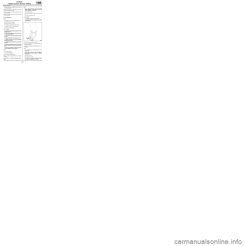
aPush the turbocharger air outlet pipe clip (15) in the
direction of the arrow.
aConnect the turbocharger air outlet pipe onto the tur-
bocharger.
aRefit:
-the turbocharger air outlet rigid pipe bolt on the
throttle valve,
-the upstream oxygen sensor (see 17B, Petrol in-
jection, Oxygen sensors: Removal - Refitting,
page 17B-13) ,
-the air filter box strut,
-the air filter box strut bolt,
-the air filter unit (see 12A, Fuel mixture, Air filter
unit: Removal - Refitting, page 12A-13) .
122666
Page 604 of 652
19B-22
EXHAUST
Catalytic converter: Removal - Refitting
K4M
19B
aThe catalytic converter cannot be separated from
the exhaust manifold.
Replace the "exhaust manifold - catalytic converter"
assembly if the catalytic converter is faulty (see 12A,
Fuel mixture, Exhaust manifold: Removal - Refit-
ting, page 12A-48) .
Page 615 of 652
19C-1
TANK
Fuel tank: Draining
K9K
19C
I - DRAINING PREPARATION OPERATION
aDisconnect the battery (see ) (MR 441, 80A, Bat-
tery).
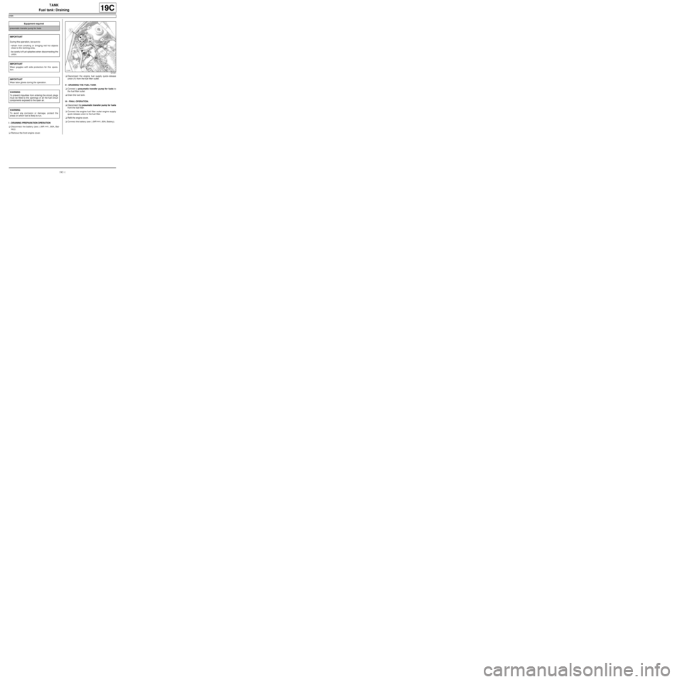
aRemove the front engine cover.aDisconnect the engine fuel supply quick-release
union (1) from the fuel filter outlet.
II - DRAINING THE FUEL TANK
aConnect a pneumatic transfer pump for fuels to
the fuel filter outlet.
aDrain the fuel tank.
III - FINAL OPERATION.
aDisconnect the pneumatic transfer pump for fuels
from the fuel filter.
aConnect the engine fuel filter outlet engine supply
quick-release union to the fuel filter.
aRefit the engine cover.
aConnect the battery (see ) (MR 441, 80A, Battery). Equipment required
pneumatic transfer pump for fuels
IMPORTANT
During this oper ation, be sure to:
-refrain from smoking or bringing red hot objects
close to the working area,
-be careful of fuel splashes when disconnecting the
union.
IMPORTANT
Wear goggles with side protectors for this opera-
tion.
IMPORTANT
Wear latex gloves during the operation.
WARNING
To prevent impurities from entering the circuit, plugs
must be fitted to the openings of all the fuel circuit
components exposed to the open air.
WARNING
To avoid any corrosion or damage, protect the
areas on which fuel is likely to run.
121441
Page 616 of 652
19C-2
TANK
Fuel tank: Draining
D4F or D7F or K4M
19C
I - DRAINING PREPARATION OPERATION
aDisconnect the battery (see ) (80A, Battery).
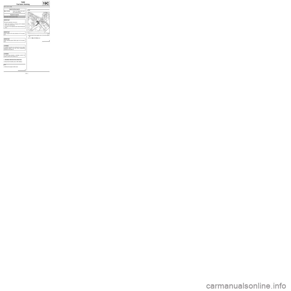
aRemove the engine oil filler neck.aDisconnect the fuel supply union (1) from the injector
rail.
aFit a T (Mot. 1311-08) union. Special tooling required
Mot. 1311-08Union for taking fuel pres-
sure measurements .
Equipment required
pneumatic transfer pump for fuels
IMPORTANT
During this oper ation, be sure to:
-refrain from smoking or bringing red hot objects
close to the working area,
-be careful of fuel splashes when disconnecting the
union.
IMPORTANT
Wear goggles with side protectors for this opera-
tion.
IMPORTANT
Wear leaktight gloves (Nitrile type) for this opera-
tion.
WARNING
To prevent impurities from entering the circuit, place
protective plugs on all fuel circuit components
exposed to the open air.
WARNING
To avoid any corrosion or damage, protect the
areas on which fuel is likely to run.
D4F
D4F
121778
Page 617 of 652
19C-3
TANK
Fuel tank: Draining
D4F or D7F or K4M
19C
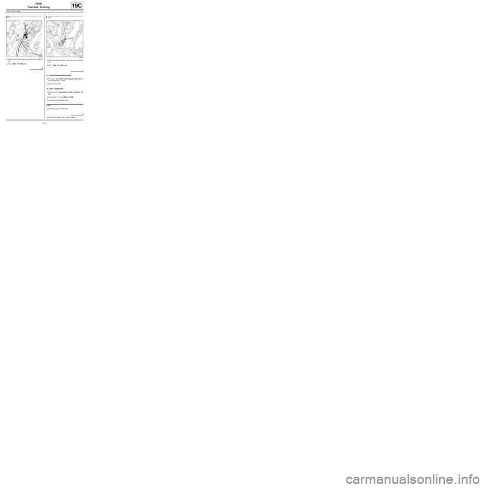
aDisconnect the fuel supply union (2) from the injector
rail.
aFit a T (Mot. 1311-08) union.aDisconnect the fuel supply union (3) from the injector
rail.
aFit a T (Mot. 1311-08) union.
II - TANK DRAINING PROCEDURE
aConnect a pneumatic transfer pump for fuels on
the outlet of the "T" union.
aDrain the fuel tank.
III - FINAL OPERATION.
aDisconnect the pneumatic transfer pump for fu-
els. .
aRemove the “T” union (Mot. 1311-08).
aConnect the fuel supply union.
aRefit the engine oil filler neck.
aConnect the battery (see ) (80A, Battery). D7F
121779
K4M
132334
D4F
Page 618 of 652
19C-4
TANK
Fuel tank: Removal - Refitting
D4F or D7F or K4M or K9K
19C
REMOVAL
I - REMOVAL PREPARATION OPERATION
aPosition the vehicle on a two-post lift (see Vehicle:
Towing and lifting) (02A, Lifting equipment).
aDisconnect the battery (see Battery: Removal - Re-
fitting) (80A, Battery).
aDrain the fuel tank (see 19C, Tank, Fuel tank:
Draining, page 19C-1) .
aLift up:
-the rear bench seat,
-the carpet.
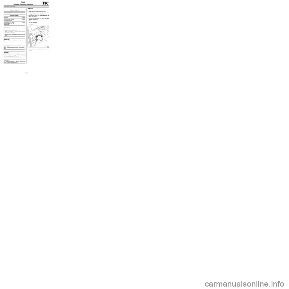
aRemove the access flap (1) to the fuel level sensor
module. Equipment requiredcomponent support
Tightening torquesm
tank bolts21 N.m
exhaust pipe rubber
mounting bush bolt21 N.m
clip between the cata-
lytic converter and the
rear silencer21 N.m
IMPORTANT
During this oper ation, be sure to:
-refrain from smoking or bringing red hot objects
close to the working area,
-be careful of fuel splashes when disconnecting the
union.
IMPORTANT
Wear leaktight gloves (Nitrile type) for this opera-
tion.
IMPORTANT
Wear goggles with side protectors for this opera-
tion.
WARNING
To prevent impurities from entering the circuit, plugs
must be fitted to the openings of all the fuel circuit
components exposed to the open air.
WARNING
To avoid any corrosion or damage, protect the
areas on which fuel is likely to run.
119692
Page 619 of 652
19C-5
TANK
Fuel tank: Removal - Refitting
D4F or D7F or K4M or K9K
19C
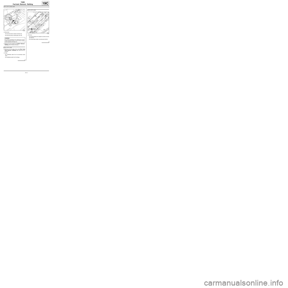
aDisconnect:
-the fuel level sensor module connector (2) ,
-the fuel level sensor module pipe union (3) .
aRemove the rear wheels (see Wheel: Removal -
Refitting) (35A, Wheels and tyres).
aRemove the rear brake drums (see Rear brake
drum: Removal - Refitting) (33A, Rear axle com-
ponents).
aUnclip:
-the handbrake cable from the secondary brake
shoe,
-the handbrake cable from the flange.aRemove:
-the clip (4) between the catalytic converter and the
rear silencer,
-the exhaust pipe rubber mounting bush bolt (5) .
119691
WARNING
To prevent impurities from entering the circuit,
place protective plugs on all fuel circuit compo-
nents exposed to the open air.
D4F or D7F or K9K
D4F or D7F or K9K
119689
Page 620 of 652
19C-6
TANK
Fuel tank: Removal - Refitting
D4F or D7F or K4M or K9K
19C
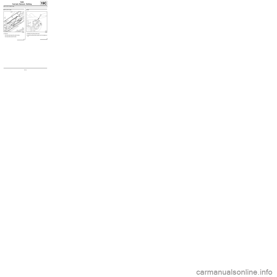
aRemove:
-the heat shield clips (6) under the tank,
-the heat shield under the tank.aRelease the parking brake lever.
aUnclip the parking brake cables from the callipers at
(7) . D4F or D7F or K9K
119435
K4M
132468
Page 621 of 652
19C-7
TANK
Fuel tank: Removal - Refitting
D4F or D7F or K4M or K9K
19C
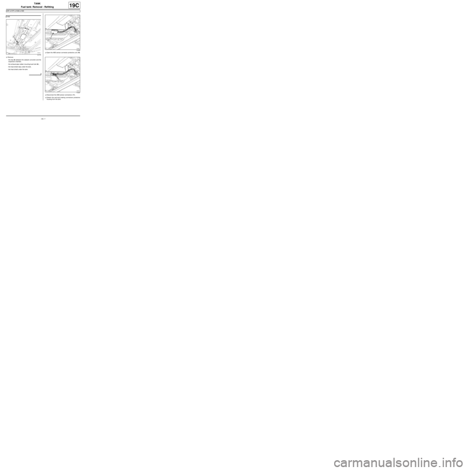
aRemove:
-the clip (8) between the catalytic converter and the
expansion chamber,
-the exhaust pipe rubber mounting bush bolt (9) ,
-the heat shield clips under the tank,
-the heat shield under the tank.aOpen the ABS sensor connector protective unit (10)
.
aDisconnect the ABS sensor connectors (11) .
aDetach the anti-lock braking connectors protective
housing from the tank. K4M
131773
119438
119437