RENAULT TWINGO 2009 2.G Engine And Peripherals Workshop Manual
Manufacturer: RENAULT, Model Year: 2009, Model line: TWINGO, Model: RENAULT TWINGO 2009 2.GPages: 652
Page 301 of 652
12A-36
FUEL MIXTURE
Inlet distributor: Removal - Refitting
D4F, and 772
12A
III - FINAL OPERATION
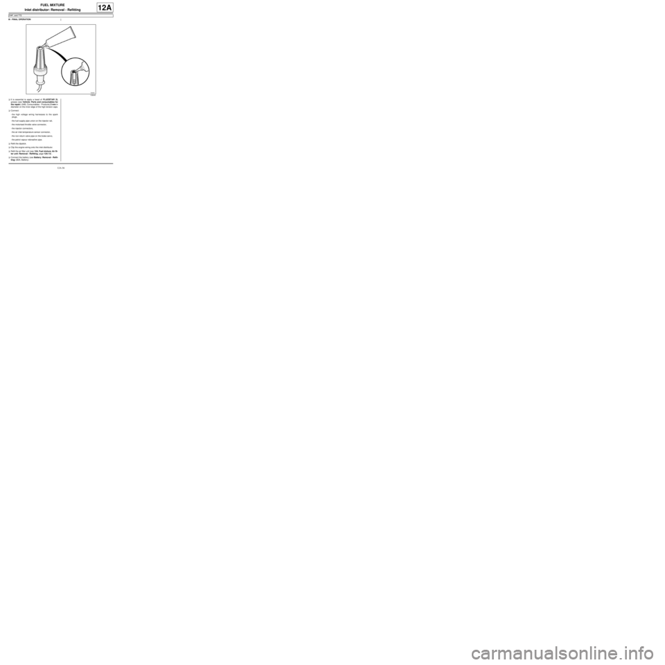
aIt is essential to apply a bead of FLUOSTAR 2L
grease (see Vehicle: Parts and consumables for
the repair) (04B, Consumables - Products) 2 mm in
diameter on the inner edge of the high tension caps.
aConnect:
-the high voltage wiring harnesses to the spark
plugs,
-the fuel supply pipe union on the injector rail,
-the motorised throttle valve connector,
-the injector connectors,
-the air inlet temperature sensor connector,
-the non-return valve pipe on the brake servo,
-the petrol vapour rebreather pipe.
aRefit the dipstick.
aClip the engine wiring onto the inlet distributor.
aRefit the air filter unit (see 12A, Fuel mixture, Air fil-
ter unit: Removal - Refitting, page 12A-13) .
aConnect the battery (see Battery: Removal - Refit-
ting) (80A, Battery).
106640
Page 302 of 652
12A-37
FUEL MIXTURE
Inlet distributor: Removal - Refitting
D4F, and 780 or 782
12A
REMOVAL
I - REMOVAL PREPARATION OPERATION
aRemove the throttle valve (see 12A, Fuel mixture,
Throttle valve: Removal - Refitting, page 12A-20)
.aRemove:
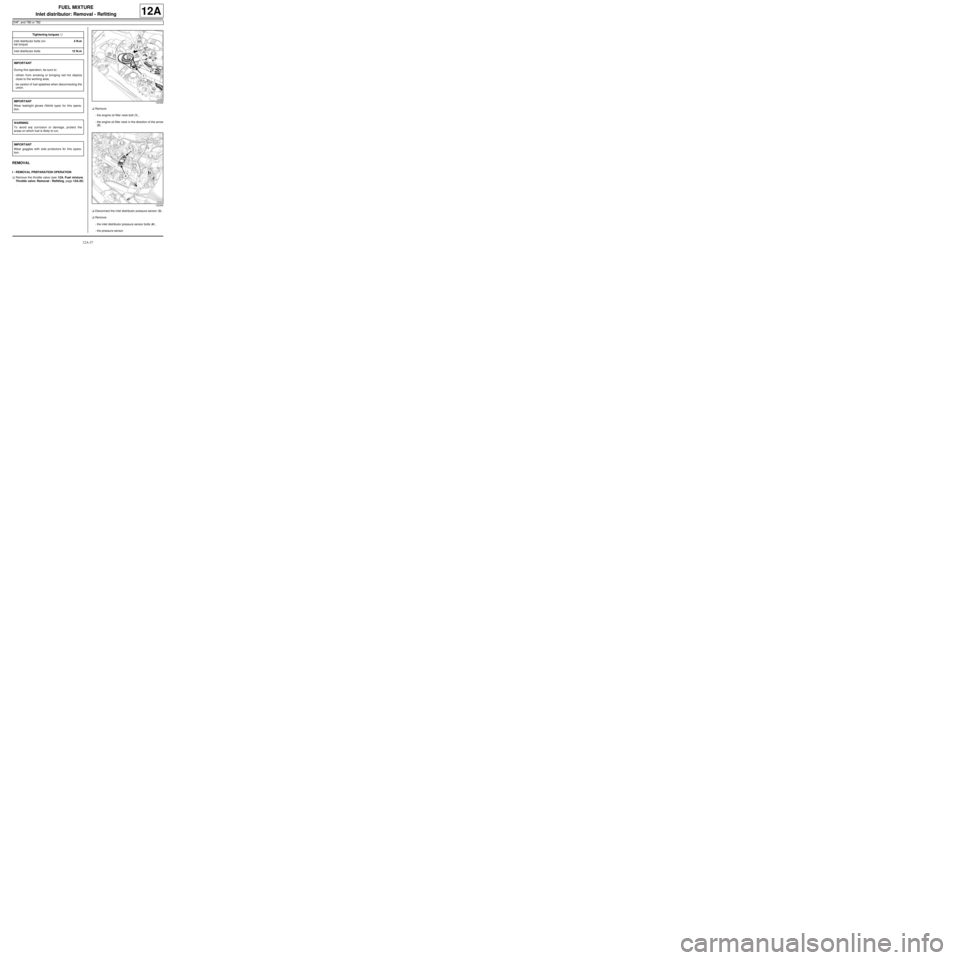
-the engine oil filler neck bolt (1) ,
-the engine oil filler neck in the direction of the arrow
(2) .
aDisconnect the inlet distributor pressure sensor (3) .
aRemove:
-the inlet distributor pressure sensor bolts (4) ,
-the pressure sensor. Tightening torquesm
inlet distributor bolts (ini-
tial torque)4 N.m
inlet distributor bolts12 N.m
IMPORTANT
During this oper ation, be sure to:
-refrain from smoking or bringing red hot objects
close to the working area,
-be careful of fuel splashes when disconnecting the
union.
IMPORTANT
Wear leaktight gloves (Nitrile type) for this opera-
tion.
WARNING
To avoid any corrosion or damage, protect the
areas on which fuel is likely to run.
IMPORTANT
Wear goggles with side protectors for this opera-
tion.
122392
122393
Page 303 of 652
12A-38
FUEL MIXTURE
Inlet distributor: Removal - Refitting
D4F, and 780 or 782
12A
aRemove the « injector rail - injector » assembly (see
17B, Petrol injection, Injector rail - Injectors: Re-
moval - Refitting, page 17B-27) .
II - OPERATION FOR REMOVAL OF PART
CONCERNED
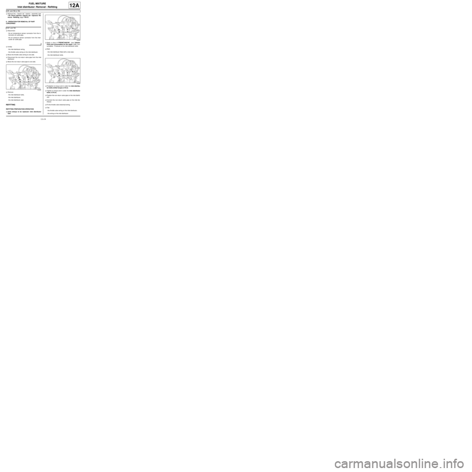
aDisconnect:
-the air temperature sensor connector from the in-
tercooler air outlet pipe,
-the air pressure sensor connector from the inter-
cooler air outlet pipe.
aUnclip:
-the inlet distributor wiring,
-the throttle valve wiring on the inlet distributor.
aMove the throttle valve wiring to one side.
aDisconnect the non-return valve pipe from the inlet
distributor.
aMove the non-return valve pipe to one side.
aRemove:
-the inlet distributor bolts,
-the inlet distributor,
-the inlet distributor seal.
REFITTING
REFITTING PREPARATION OPERATION
aparts always to be replaced: inlet distributor
seal.aApply a drop of FRENETANCHE (see Vehicle:
Parts and consumables for the repair) (04B, Con-
sumables - Products) to the inlet distributor bolts.
aRefit:
-the inlet distributor fitted with a new seal,
-the inlet distributor bolts.
aPretighten to torque and in order the inlet distribu-
tor bolts (initial torque) (4 N.m).
aTighten to torque and in order the inlet distributor
bolts (12 N.m).
aPosition the non-return valve pipe on the inlet distrib-
utor.
aConnect the non-return valve pipe on the inlet dis-
tributor.
aFit the throttle valve electrical wiring.
aClip:
-the throttle valve wiring on the inlet distributor,
-the wiring on the inlet distributor. D4F, and 780
120955
120955
120955
Page 304 of 652
12A-39
FUEL MIXTURE
Inlet distributor: Removal - Refitting
D4F, and 780 or 782
12A
aConnect:
-the air pressure sensor connector on the intercool-
er air outlet pipe,
-the air temperature sensor connector on the inter-
cooler air outlet pipe.
aRefit:
-the injector rail (see 17B, Petrol injection, Injec-
tor rail - Injectors: Removal - Refitting, page
17B-27)
-the distributor pressure sensor,
-the pressure sensor bolt.
aConnect the distributor pressure sensor connector.
aRefit:
-the filler neck,
-the filler neck bolt,
-the throttle valve (see 12A, Fuel mixture, Throttle
valve: Removal - Refitting, page 12A-20) . D4F, and 780
Page 305 of 652
12A-40
FUEL MIXTURE
Inlet distributor: Removal - Refitting
K4M
12A
REMOVAL
I - REMOVAL PREPARATION OPERATION
aDisconnect the battery (see Battery: Removal - Re-
fitting) (80A, Battery).
aRemove:
-the windscreen wiper arms (see Windscreen wip-
er arm: Removal - Refitting) (85A, Wiping -
Washing),-the scuttle panel grille (see Scuttle panel grille:
Removal - Refitting) (56A, Exterior equipment),
-the scoop under the scuttle panel grille (see Scoop
under the scuttle panel grille: Removal - Refit-
ting) (56A, Exterior equipment),
-the dipstick.
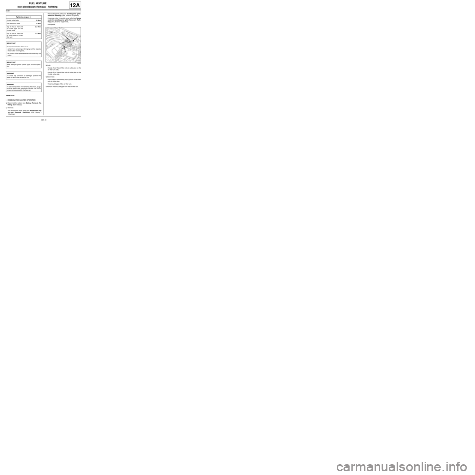
aUndo:
-the clip (1) of the air filter unit air outlet pipe on the
air filter unit side,
-the clip (2) of the air filter unit air outlet pipe on the
throttle valve side.
aDisconnect:
-the oil vapour rebreathing pipe (3) from the air filter
unit air outlet pipe,
-the air outlet pipe of the air filter unit.
aRemove the air outlet pipe from the air filter box. Tightening torquesm
throttle valve bolts10 N.m
inlet distributor bolts12 N.m
clip of the air filter unit
air outlet pipe on the
throttle valve3.5 N.m
clip of the air filter unit
air outlet pipe on the air
filter unit3.5 N.m
IMPORTANT
During this oper ation, be sure to:
-refrain from smoking or bringing red hot objects
close to the working area,
-be careful of fuel splashes when disconnecting the
union.
IMPORTANT
Wear leaktight gloves (Nitrile type) for this opera-
tion.
WARNING
To avoid any corrosion or damage, protect the
areas on which fuel is likely to run.
WARNING
To prevent impurities from entering the circuit, plugs
must be fitted to the openings of all the fuel circuit
components exposed to the open air.
132382
Page 306 of 652
12A-41
FUEL MIXTURE
Inlet distributor: Removal - Refitting
K4M
12A
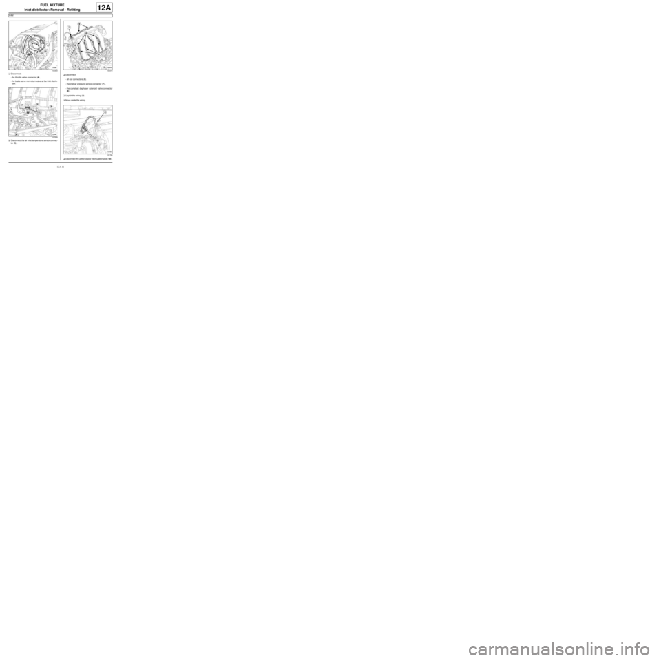
aDisconnect:
-the throttle valve connector (4) ,
-the brake servo non-return valve at the inlet distrib-
utor.
aDisconnect the air inlet temperature sensor connec-
tor (5) .aDisconnect:
-all coil connectors (6) ,
-the inlet air pressure sensor connector (7) ,
-the camshaft dephaser solenoid valve connector
(8) .
aUnpick the wiring (9) .
aMove aside the wiring.
aDisconnect the petrol vapour recirculation pipe (10) .
132383
132369132370
131766
Page 307 of 652
12A-42
FUEL MIXTURE
Inlet distributor: Removal - Refitting
K4M
12A
II - REMOVAL OPERATION
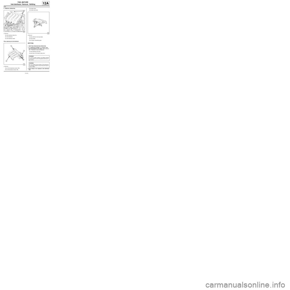
aRemove:
-the inlet distributor bolts (11) ,
-the inlet distributor,
-the inlet distributor seals.
When replacing the inlet distributor
aRemove:
-the air inlet temperature sensor (12) ,
-the air inlet pressure sensor (13) ,-the throttle valve,
-the throttle valve seal.
aRemove:
-the bolts (15) from the heat shield,
-the heat shield,
-the oil vapour rebreathing pipe.
REFITTING
I - REFITTING PREPARATION OPERATION
aUse SURFACE CLEANER (see Vehicle: Parts
and consumables for the repair) (04B, Consuma-
bles - Products) to clean and degrease:
-the inlet distributor joint face,
-the joint face of the injector holder shim.
aparts always to be replaced: inlet distributor
seal.
132371
132438
132439
WARNING
To ensure proper sealing, the gasket surfaces
must be clean, dry and not greasy (avoid any fin-
ger mar ks).
WARNING
Do not scrape the joint faces of the aluminium,
any damage caused to the joint face will result in
a risk of leaks.
Page 308 of 652
12A-43
FUEL MIXTURE
Inlet distributor: Removal - Refitting
K4M
12A
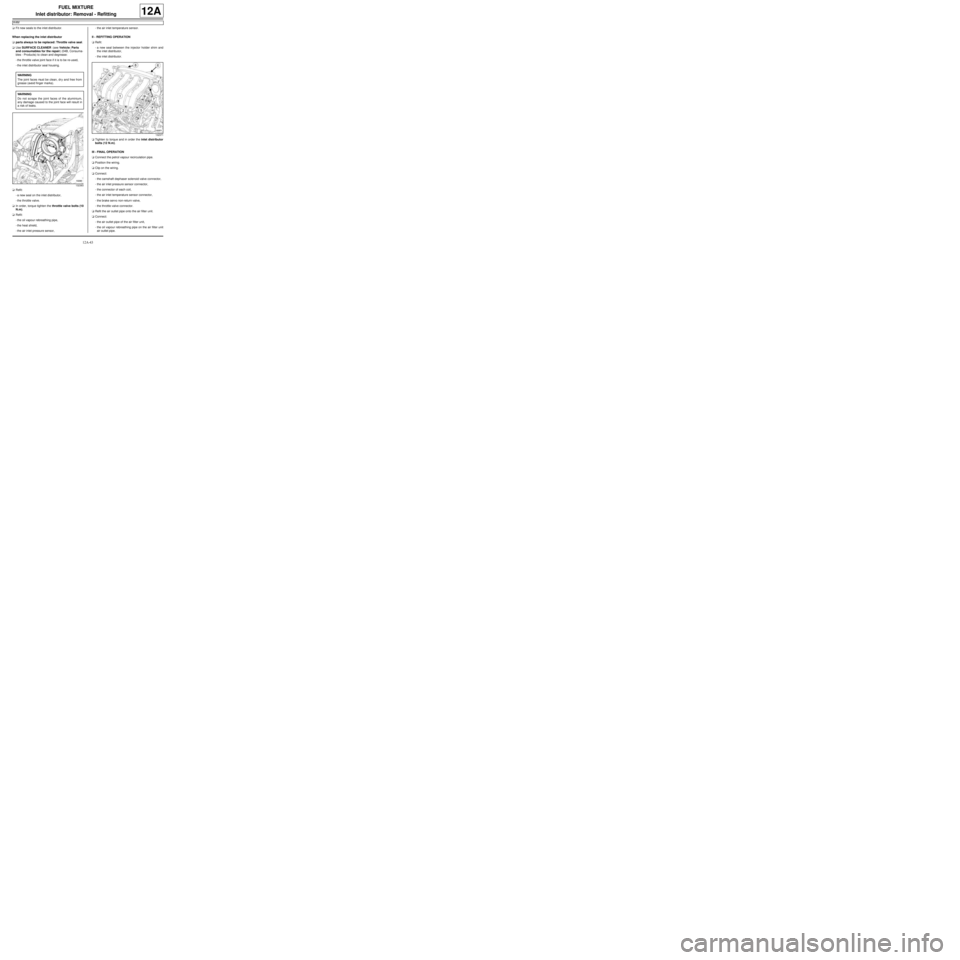
aFit new seals to the inlet distributor.
When replacing the inlet distributor
aparts always to be replaced: Throttle valve seal.
aUse SURFACE CLEANER (see Vehicle: Parts
and consumables for the repair) (04B, Consuma-
bles - Products) to clean and degrease:
-the throttle valve joint face if it is to be re-used,
-the inlet distributor seal housing.
aRefit:
-a new seal on the inlet distributor,
-the throttle valve.
aIn order, torque tighten the throttle valve bolts (10
N.m).
aRefit:
-the oil vapour rebreathing pipe,
-the heat shield,
-the air inlet pressure sensor,-the air inlet temperature sensor.
II - REFITTING OPERATION
aRefit:
-a new seal between the injector holder shim and
the inlet distributor,
-the inlet distributor.
aTighten to torque and in order the inlet distributor
bolts (12 N.m).
III - FINAL OPERATION
aConnect the petrol vapour recirculation pipe.
aPosition the wiring.
aClip on the wiring.
aConnect:
-the camshaft dephaser solenoid valve connector,
-the air inlet pressure sensor connector,
-the connector of each coil,
-the air inlet temperature sensor connector,
-the brake servo non-return valve,
-the throttle valve connector.
aRefit the air outlet pipe onto the air filter unit.
aConnect:
-the air outlet pipe of the air filter unit,
-the oil vapour rebreathing pipe on the air filter unit
air outlet pipe. WARNING
The joint faces must be clean, dr y and free from
grease (avoid finger marks).
WARNING
Do not scrape the joint faces of the aluminium,
any damage caused to the joint face will result in
a risk of leaks.
132383
132371
Page 309 of 652

12A-44
FUEL MIXTURE
Inlet distributor: Removal - Refitting
K4M
12A
aTorque tighten:
-the clip of the air filter unit air outlet pipe on the
throttle valve (3.5 N.m),
-the clip of the air filter unit air outlet pipe on the
air filter unit (3.5 N.m).
aRefit:
-the dipstick,
-the scoop under the scuttle panel grille (see Scoop
under the scuttle panel grille: Removal - Refit-
ting) (56A, Exterior equipment),
-the scuttle panel grille (see Scuttle panel grille:
Removal - Refitting) (56A, Exterior equipment),
-the windscreen wiper arms (see Windscreen wip-
er arm: Removal - Refitting) (85A, Wiping -
Washing).
aConnect the battery (see Battery: Removal - Refit-
ting) (80A, Battery).
Page 310 of 652
12A-45
FUEL MIXTURE
Injector holder shim: Removal - Refitting
K4M
12A
REMOVAL
I - REMOVAL PREPARATION OPERATION
aDisconnect the battery (see ) (80A, Battery).
aRemove:
-the windscreen wiper arms (see Windscreen wip-
er arm: Removal - Refitting) (85A, Wiping -
Washing),
-the scuttle panel grille (see Scuttle panel grille:
Removal - Refitting) (56A, Exterior equipment),
-the scoop under the scuttle panel grille (see Scoop
under the scuttle panel grille: Removal - Refit-
ting) (56A, Exterior equipment).aRemove:
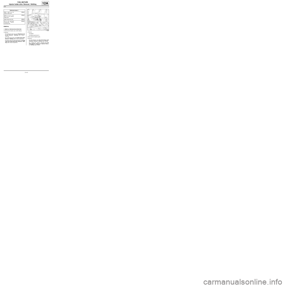
-the dipstick,
-the dipstick guide bolts (1) .
aMove aside the dipstick guide.
aRemove:
-the inlet distributor (see 12A, Fuel mixture, Inlet
distributor: Removal - Refitting, page 12A-29) ,
-the « injector rail - injector » assembly (see 17B,
Petrol injection, Injector rail - Injectors: Remov-
al - Refitting, page 17B-27) . Tightening torquesm
bolts 1 and 2 on the
injector holder shim30 N.m
bolts 3, 4, 5, 6, 7, 8, 9
and 10 on the injector
holder shim25 N.m
upper timing cover bolt40 N.m
bolt on the right-hand
suspended engine
mounting cover62 N.m
132368