light RENAULT TWINGO 2009 2.G Engine And Peripherals Owner's Guide
[x] Cancel search | Manufacturer: RENAULT, Model Year: 2009, Model line: TWINGO, Model: RENAULT TWINGO 2009 2.GPages: 652
Page 241 of 652
11A-124
TOP AND FRONT OF ENGINE
Cylinder head: Removal - Refitting
K4M
11A
-the right-hand suspended engine mounting (see
19D, Engine mounting, Right-hand suspended
engine mounting: Removal - Refitting, page
19D-13) ,
-the lower engine tie-bar (see 19D, Engine mount-
ing, Lower engine tie-bar: Removal - Refitting,
page 19D-18) ,
-the air filter unit (see 12A, Fuel mixture, Air filter
unit: Removal - Refitting, page 12A-13) ,
-the accessories belt (see 11A, Top and front of
engine, Accessories belt: Removal - Refitting,
page 11A-3) ,
-the front upper cross member (see Front upper
cross member: Removal - Refitting) (42A, Upper
front structure),
-the bonnet catch (see Bonnet lock: Removal -
Refitting) (52A, Non-side opening element mecha-
nisms),
-the headlights (see Halogen headlight: Removal
- Refitting) (80B, Headlights),
-the front bumper (see Front bumper: Removal -
Refitting) (55A, Exterior protection),
-the front right-hand wheel arch liner (see Front
wheel arch liner: Removal - Refitting) (55A, Ex-
terior protection),
-the front right-hand wheel (see Wheel: Removal -
Refitting) (35A, Wheels and tyres),
-the oil decanter (see 11A, Top and front of en-
gine, Oil decanter: Removal - Refitting, page
11A-147) ,
-the inlet distributor (see 12A, Fuel mixture, Inlet
distributor: Removal - Refitting, page 12A-29) ,
-the throttle valve (see 12A, Fuel mixture, Throttle
valve: Removal - Refitting, page 12A-20) ,
-the coils (see 17A, Ignition, Coils: Removal - Re-
fitting, page 17A-1) ,
-the scoop under the scuttle panel grille (see Scoop
under the scuttle panel grille: Removal - Refit-
ting) (56A, Exterior equipment),
-the scuttle panel grille (see Scuttle panel grille:
Removal - Refitting) (56A, Exterior equipment),
-the windscreen wiper arms (see Windscreen wip-
er arm: Removal - Refitting) (85A, Wiping -
Washing).
aPerform the following operations:
-fill the gearbox (see Manual gearbox oils: Drain-
ing - Filling) (21A, Manual gearbox).-fill and bleed the coolant circuit (see 19A, Cooling,
Cooling system: Draining - Refilling, page 19A-
9) .
aRefit the engine undertray.
aConnect the battery (see Battery: Removal - Refit-
ting) (80A, Battery).
Page 252 of 652
11A-135
TOP AND FRONT OF ENGINE
Camshaft dephaser: Removal - Refitting
K4M
11A
REMOVAL
I - REMOVAL PREPARATION OPERATION
aPosition the vehicle on a two-post lift (see Vehicle:
Towing and lifting) (02A, Lifting equipment).
aDisconnect the battery (see Battery: Removal - Re-
fitting) (80A, Battery).
aRemove:
-the engine undertray,
-the front right-hand wheel (see Wheel: Removal -
Refitting) (35A, Wheels and tyres),
-the front right-hand wheel arch liner (see Front
wheel arch liner: Removal - Refitting) (55A, Ex-
terior protection),
-the front bumper (see Front bumper: Removal -
Refitting) (55A, Exterior protection),
-the headlights (see Halogen headlight: Removal
- Refitting) (80B, Headlights),
-the bonnet catch (see Bonnet lock: Removal -
Refitting) (52A, Non-side opening element mecha-
nisms),
-the front upper cross member (see Front upper
cross member: Removal - Refitting) (42A, Upper
front structure),
-the accessories belt (see 11A, Top and front of
engine, Accessories belt: Removal - Refitting,
page 11A-3) ,
-the air filter unit (see 12A, Fuel mixture, Air filter
unit: Removal - Refitting, page 12A-13) ,
-the throttle valve (see 12A, Fuel mixture, Throttle
valve: Removal - Refitting, page 12A-20) ,
-the windscreen wiper arms (see Windscreen wip-
er arm: Removal - Refitting) (85A, Wiping -
Washing),
-the scuttle panel grille (see Scuttle panel grille:
Removal - Refitting) (56A, Exterior equipment),
-the scoop under the scuttle panel grille (see Scoop
under the scuttle panel grille: Removal - Refit-
ting) (56A, Exterior equipment),-the right-hand suspended engine mounting (see
19D, Engine mounting, Right-hand suspended
engine mounting: Removal - Refitting, page
19D-13) ,
-the crankshaft accessories pulley (see 11A, Top
and front of engine, Crankshaft accessories
pulley: Removal - Refitting, page 11A-20) ,
-the timing belt (see 11A, Top and front of engine,
Timing belt: Removal - Refitting, page 11A-27) .
II - REMOVAL OPERATION
aPosition the (Mot. 1490-01) (1) .
aRemove the camshaft dephaser pulley blanking cov-
er (2) . Special tooling required
Mot. 1490-01For locking and adjusting the
camshaft pulle ys.
103265
Page 254 of 652
11A-137
TOP AND FRONT OF ENGINE
Camshaft dephaser: Removal - Refitting
K4M
11A
aMechanically lock the camshaft dephaser pulley by
rotating it to the left or right using a tubular hexagon
box spanner.
aCheck that the camshaft dephaser pulley is correctly
locked (the hub does not rotate in relation to the
wheel to the left or right).
aIf the hub rotates in relation to the wheel, the cam-
shaft dephaser pulley is faulty and must be replaced.
aDegrease the end of the inlet camshaft (timing end)
and clean the bores and bearing faces of the cam-
shaft dephaser pulley.
II - REFITTING OPERATION
aRefit:
-the exhaust camshaft pulley.
-the camshaft dephaser pulley.
aFit without tightening:
-the exhaust camshaft pulley bolt,
-the camshaft dephaser pulley nut.
III - FINAL OPERATION
aRefit:
-the timing belt (see 11A, Top and front of engine,
Timing belt: Removal - Refitting, page 11A-27) ,
-the right-hand suspended engine mounting (see
19D, Engine mounting, Right-hand suspended
engine mounting: Removal - Refitting, page
19D-13) ,-the scoop under the scuttle panel grille (see Scoop
under the scuttle panel grille: Removal - Refit-
ting) (56A, Exterior equipment),
-the scuttle panel grille (see Scuttle panel grille:
Removal - Refitting) (56A, Exterior equipment),
-the windscreen wiper arms (see Windscreen wip-
er arm: Removal - Refitting) (85A, Wiping -
Washing),
-the throttle valve (see 12A, Fuel mixture, Throttle
valve: Removal - Refitting, page 12A-20) ,
-the air filter unit (see 12A, Fuel mixture, Air filter
unit: Removal - Refitting, page 12A-13) ,
-the accessories belt (see 11A, Top and front of
engine, Accessories belt: Removal - Refitting,
page 11A-3) ,
-the front upper cross member (see Front upper
cross member: Removal - Refitting) (42A, Upper
front structure),
-the bonnet catch (see Bonnet lock: Removal -
Refitting) (52A, Non-side opening element mecha-
nisms),
-the headlights (see Halogen headlight: Removal
- Refitting) (80B, Headlights),
-the front bumper (see Front bumper: Removal -
Refitting) (55A, Exterior protection),
-the front right-hand wheel arch liner (see Front
wheel arch liner: Removal - Refitting) (55A, Ex-
terior protection),
-the front right-hand wheel (see Wheel: Removal -
Refitting) (35A, Wheels and tyres),
-the engine undertray.
aConnect the battery (see Battery: Removal - Refit-
ting) (80A, Battery).
111340
Page 255 of 652
11A-138
TOP AND FRONT OF ENGINE
Camshaft seal, timing end: Removal - Refitting
K9K
11A
PARTS AND CONSUMABLES FOR THE
REPAIR WORK
aParts always to be replaced:
-the timing end camshaft seal,
-the timing end camshaft stud,
aConsumables (see Vehicle: Parts and consuma-
bles for the repair) (MR 411, 04B, Consumables -
Products):
-SURFACE CLEANER.
REMOVAL
I - REMOVAL PREPARATION OPERATION
aPosition the vehicle on a two-post lift (see Vehicle:
Towing and lifting) (see MR 411, 02A, Lifting
equipment).
aDisconnect the battery (see Battery: Removal - Re-
fitting) (see MR 411, 80A, Battery).
aRemove:
-the windscreen wiper arms (see Windscreen wip-
er arm: Removal - Refitting) (MR 411, 85A, Wip-
ers - Washers),
-the scuttle panel grille (see Scuttle panel grille:
Removal - Refitting) (MR 412, 56A, Exterior
equipment),-the scoop under the scuttle panel grille (see Scoop
under the scuttle panel grille: Removal - Refit-
ting) (MR 412, 56A, Exterior equipment),
-the front right-hand wheel (see Wheel: Removal -
Refitting) (MR 411, 35A, Wheels and tyres),
-the front right-hand wheel arch liner (see Front
wheel arch liner: Removal - Refitting) (MR 412,
55A, Exterior protection),
-the front bumper (see Front bumper: Removal -
Refitting) (MR 412, 55A, Exterior protection),
-the halogen headlights (see Halogen headlight:
Removal - Refitting) (MR 411, 80B, Halogen
headlights),
-the front upper cross member (see Front upper
cross member: Removal - Refitting) (MR 412,
42A, Upper front structure),
-the lower engine tie-bar (see 19D, Engine mount-
ing, Lower engine tie-bar: Removal - Refitting,
page 19D-18) ,
-the right-hand suspended engine mounting (see
19D, Engine mounting, Right-hand suspended
engine mounting: Removal - Refitting, page
19D-13) ,
-the accessories belt (see 11A, Top and front of
engine, Accessories belt: Removal - Refitting,
page 11A-3) ,
-the crankshaft accessories pulley (see 11A, Top
and front of engine, Crankshaft accessories
pulley: Removal - Refitting, page 11A-20) ,
-the camshaft position sensor (see 13B, Diesel in-
jection, Camshaft position sensor: Removal -
Refitting, page 13B-14) ,
-the timing belt (see 11A, Top and front of engine,
Timing belt: Removal - Refitting, page 11A-27) . Special tooling required
Mot. 1606High pressure pump pulley
support tool.
Mot. 1632Tool for fitting camshaft PTFE
seal
Mot. 799-01Timing gear wheel immobil-
iser.
Equipment required
roller-type stud removal tool
cylinder head bolt tightening gauge (angular mea-
suring type)
Tightening torquesm
camshaft hub nut30 Nm + 86˚ ±± ± ±
6˚
Page 257 of 652

11A-140
TOP AND FRONT OF ENGINE
Camshaft seal, timing end: Removal - Refitting
K9K
11A
III - FINAL OPERATION.
aRefit:
-the camshaft pulley hub,
-the camshaft pulley hub nut, locking it using the
(Mot. 799-01).
aTorque and angle tighten using a cylinder head
bolt tightening gauge (angular measuring type)
the camshaft hub nut ( 30 Nm + 86˚ ±± ± ±
6˚).
aRefit the camshaft pulley wheel.
aFit the camshaft pulley wheel bolts, without tighten-
ing them.
aRefit:
-the timing belt (see 11A, Top and front of engine,
Timing belt: Removal - Refitting, page 11A-27) ,
-the camshaft position sensor (see 13B, Diesel in-
jection, Camshaft position sensor: Removal -
Refitting, page 13B-14) ,
-the crankshaft accessories pulley (see 11A, Top
and front of engine, Crankshaft accessories
pulley: Removal - Refitting, page 11A-20) ,
-the accessories belt (see 11A, Top and front of
engine, Accessories belt: Removal - Refitting,
page 11A-3) ,
-the right-hand suspended engine mounting (see
19D, Engine mounting, Right-hand suspended
engine mounting: Removal - Refitting, page
19D-13) ,
-the lower engine tie-bar (see 19D, Engine mount-
ing, Lower engine tie-bar: Removal - Refitting,
page 19D-18) ,
-the front upper cross member (see Front upper
cross member: Removal - Refitting) (MR 412,
42A, Upper front structure),
-the halogen headlights (see Halogen headlight:
Removal - Refitting) (MR 411, 80B, Halogen
headlights),
-the front bumper (see Front bumper: Removal -
Refitting) (MR 412, 55A, Exterior protection),
-the front right-hand wheel arch liner (see Front
wheel arch liner: Removal - Refitting) (MR 412,
55A, Exterior protection),
-the front right-hand wheel (see Wheel: Removal -
Refitting) (MR 411, 35A, Wheels and tyres),
-the scoop under the scuttle panel grille (see Scoop
under the scuttle panel grille: Removal - Refit-
ting) (MR 412, 56A, Exterior equipment),-the scuttle panel grille (see Scuttle panel grille:
Removal - Refitting) (MR 412, 56A, Exterior
equipment),
-the windscreen wiper arms (see Windscreen wip-
er arm: Removal - Refitting) (MR 411, 85A, Wip-
ers - Washers).
aConnect the battery (see Battery: Removal - Refit-
ting) (see MR 411, 80A, Battery).
Page 258 of 652
11A-141
TOP AND FRONT OF ENGINE
Camshaft seal, timing end: Removal - Refitting
K4M
11A
REMOVAL
I - REMOVAL PREPARATION OPERATION
aPosition the vehicle on a two-post lift (see Vehicle:
Towing and lifting) (02A, Lifting equipment).
aDisconnect the battery (see Battery: Removal - Re-
fitting) (80A, Battery).
aRemove:
-the engine undertray,
-the front right-hand wheel (see Wheel: Removal -
Refitting) (35A, Wheels and tyres),
-the front right-hand wheel arch liner (see Front
wheel arch liner: Removal - Refitting) (55A, Ex-
terior protection),
-the front bumper (see Front bumper: Removal -
Refitting) (55A, Exterior protection),
-the headlights (see Halogen headlight: Removal
- Refitting) (80B, Headlights),
-the bonnet catch (see Bonnet lock: Removal -
Refitting) (52A, Non-side opening element mecha-
nisms),
-the front upper cross member (see Front upper
cross member: Removal - Refitting) (42A, Upper
front structure),
-the accessories belt (see 11A, Top and front of
engine, Accessories belt: Removal - Refitting,
page 11A-3) ,
-the air filter unit (see 12A, Fuel mixture, Air filter
unit: Removal - Refitting, page 12A-13) ,
-the throttle valve (see 12A, Fuel mixture, Throttle
valve: Removal - Refitting, page 12A-20) ,
-the windscreen wiper arms (see Windscreen wip-
er arm: Removal - Refitting) (85A, Wiping -
Washing),
-the scuttle panel grille (see Scuttle panel grille:
Removal - Refitting) (56A, Exterior equipment),
-the scoop under the scuttle panel grille (see Scoop
under the scuttle panel grille: Removal - Refit-
ting) (56A, Exterior equipment),-the right-hand suspended engine mounting (see
19D, Engine mounting, Right-hand suspended
engine mounting: Removal - Refitting, page
19D-13) ,
-the crankshaft accessories pulley (see 11A, Top
and front of engine, Crankshaft accessories
pulley: Removal - Refitting, page 11A-20) ,
-the timing belt (see 11A, Top and front of engine,
Timing belt: Removal - Refitting, page 11A-27) ,
-the camshaft dephaser (see 11A, Top and front of
engine, Camshaft dephaser: Removal - Refit-
ting, page 11A-135) .
II - REMOVAL OPERATION
a
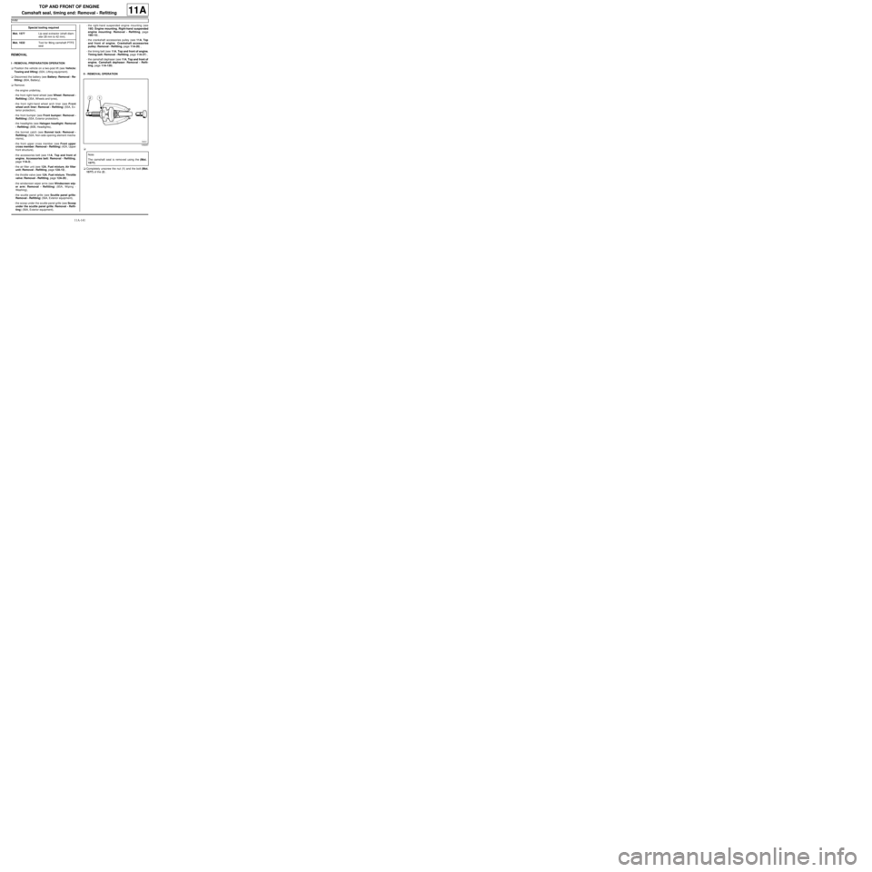
aCompletely unscrew the nut (1) and the bolt (Mot.
1577) of the (2) . Special tooling required
Mot. 1577Lip seal e xtractor (shaft diam-
eter 28 mm to 42 mm).
Mot. 1632Tool for fitting camshaft PTFE
seal
105257
Note:
The camshaft seal is removed using the (Mot.
1577).
Page 262 of 652

11A-145
TOP AND FRONT OF ENGINE
Camshaft seal, timing end: Removal - Refitting
K4M
11A
aFit the cover (13) and the collar nut (14) of the (Mot.
1632).
aScrew on the collar nut until the cover touches the
cylinder head.
aRemove:
-the collar nut from the (Mot. 1632),
-the cover from the (Mot. 1632),
-the stud from the (Mot. 1632).
III - FINAL OPERATION
aRefit:
-the camshaft dephaser (see 11A, Top and front of
engine, Camshaft dephaser: Removal - Refit-
ting, page 11A-135) ,
-the timing belt (see 11A, Top and front of engine,
Timing belt: Removal - Refitting, page 11A-27) ,
-the right-hand suspended engine mounting (see
19D, Engine mounting, Right-hand suspended
engine mounting: Removal - Refitting, page
19D-13) ,
-the scoop under the scuttle panel grille (see Scoop
under the scuttle panel grille: Removal - Refit-
ting) (56A, Exterior equipment),
-the scuttle panel grille (see Scuttle panel grille:
Removal - Refitting) (56A, Exterior equipment),
-the windscreen wiper arms (see Windscreen wip-
er arm: Removal - Refitting) (85A, Wiping -
Washing),-the throttle valve (see 12A, Fuel mixture, Throttle
valve: Removal - Refitting, page 12A-20) ,
-the air filter unit (see 12A, Fuel mixture, Air filter
unit: Removal - Refitting, page 12A-13) ,
-the accessories belt (see 11A, Top and front of
engine, Accessories belt: Removal - Refitting,
page 11A-3) ,
-the front upper cross member (see Front upper
cross member: Removal - Refitting) (42A, Upper
front structure),
-the bonnet catch (see Bonnet lock: Removal -
Refitting) (52A, Non-side opening element mecha-
nisms),
-the headlights (see Halogen headlight: Removal
- Refitting) (80B, Headlights),
-the front bumper (see Front bumper: Removal -
Refitting) (55A, Exterior protection),
-the front right-hand wheel arch liner (see Front
wheel arch liner: Removal - Refitting) (55A, Ex-
terior protection),
-the front right-hand wheel (see Wheel: Removal -
Refitting) (35A, Wheels and tyres),
-the engine undertray.
aConnect the battery (see Battery: Removal - Refit-
ting) (80A, Battery).
126222
Page 328 of 652
12B-3
TURBOCHARGING
Turbocharging: Precautions for the repair
D4F or K9K
12B
One by one, clean the pipes removed with the parts
washer :
-brush as much of the inside of the pipe as possible
(only use brushes with plastic bristles),
-wash plenty of cleaning product from the cleaning sta-
tion through the pipe,
-allow the cleaned pipe to drain by standing it upright,
-ensure the cleaning product has drained out com-
pletely (check areas where liquid may be retained,
e.g. gaiters, resonators etc.).
Dry the pipes one by one using a compressed air spray
gun.
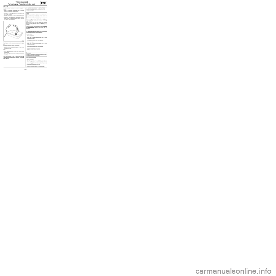
For pipes comprising several components:
-assemble the components, taking note of their correct
fitting position (10) .
Refit:
-the air pipe(between the air filter unit and the turbo-
charger) (A) ,
-the air pipe (B) (between the turbocharger and the in-
tercooler).
Refit the intercooler, if fitted to the vehicle (see 12B,
Turbocharging, Intercooler: Removal - Refitting,
page 12B-18) .V - LUBRICATION CIRCUIT**: INSTRUCTIONS
FOLLOWING MECHANICAL DAMAGE TO THE
TURBOCHARGER
Drain the engine oil (see 10A, Engine and cylinder
block assembly, Engine oil: Draining - Refilling,
page 10A-22) .
Replace the oil filter (see 10A, Engine and cylinder
block assembly, Oil filter: Removal - Refitting, page
10A-29) .
Only fill the engine with a suitable oil type (see Engine
oil: Specifications) (Technical Note 6013A, 04A, Lu-
bricants).
VI - GENERAL INSTRUCTIONS TO BE FOLLOWED
WHEN REMOVING A TURBOCHARGER
Always replace:
-the oil supply pipe:
•if the pipe is blocked, even partially (due to scale,
carbonised oil etc.),
•if the pipe is fitted with self-retaining seals.
-the oil return pipe:
•if the pipe is blocked, even partially (due to scale,
carbonised oil etc.),
•if the pipe is fitted with self-retaining seals.
-all seals that have been removed,
-all fittings that have been removed.
When starting the engine:
-do not accelerate,
-allow the engine to run for 1 minute,the time taken for
the oil circuit pressure to increase (until the oil pres-
sure warning light on the instrument panel goes out),
-accelerate several times at no load,
-check the air circuit and the oil circuit for leaks.
112771
Note:
(**) These instructions relating to the lubrication cir-
cuit must always be followed in all cases of
mechanical damage as listed above.
WARNING
Failure to observe the following procedure may lead
to destr uction of the turbocharger.
Page 390 of 652
13B-29
DIESEL INJECTION
Flow actuator: Removal - Refitting
K9K
13B
REFITTING
I - REFITTING OPERATION FOR PART
CONCERNED
a
aFit the fuel flow actuator onto the high pressure
pump.
aTighten the fuel flow actuator bolts on the high pres-
sure pump until contact is made, without tightening
them.
aTorque tighten the fuel flow actuator bolts on the
high pressure pump (6 Nm).II - FINAL OPERATION.
a
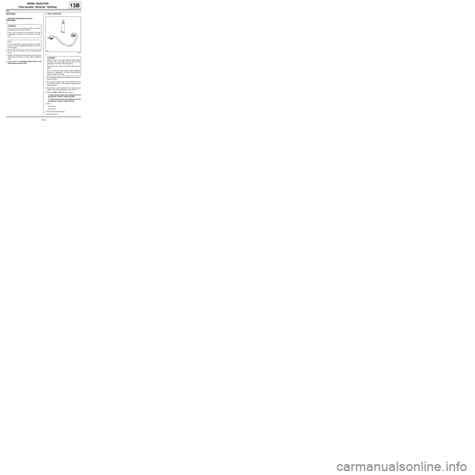
aFit a new high pressure pipe between the rail and in-
jector number 4.
aFit the high pressure pipe unions between the rail
and injector number 4 until contact is made, without
tightening them.
aFit and lock a new clip between the high pressure
pipes on the rail and injectors number 3 and 4.
aUsing the (Mot. 1746), tighten to torque:
-the high pressure pipe unions between the rail
and injector number 4 (yellow) (24 Nm),
-the high pressure pipe unions between the rail
and injector number 4 (silver) (28 Nm).
aRefit:
-the channel,
-the neck nut.
aFit the neck wiring harness.
aClip the neck on. WARNING
Do not remove the blanking plugs from each
component until the last moment.
Also, do not remove the components from their
packaging until they are to be fitted to the vehi-
cle.
Note:
Do not lubricate the seals with grease or old die-
sel fuel. Use the applicator provided in the kit for
the new part.
20960
WARNING
Before fitting a new high pressure pipe, lightly
lubricate the nut threads with the oil from the
applicator provided in the new parts kit.
Be careful not to allow oil into the high pressure
pipe.
Do not lubricate high pressure pipes supplied
without an applicator, as these high pressure
pipes are self-lubr icating.
Page 398 of 652
13B-37
DIESEL INJECTION
High pressure pipe between pump and rail: Removal - Refitting
K9K
13B
II - OPERATION FOR REMOVAL OF PART
CONCERNED
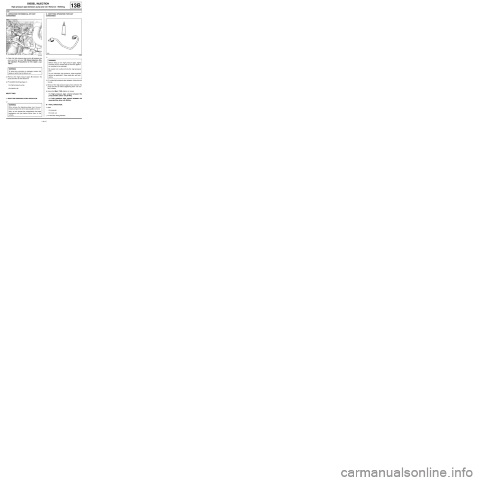
aClean the high pressure pipe unions (6) between the
pump and the rail (see 13B, Diesel injection, Die-
sel injection: Precautions for the repair, page
13B-1) .
aRemove the high pressure pipe (6) between the
pump and the rail and discard it.
aFit suitable blanking plugs on:
-the high pressure pump,
-the injector rail.
REFITTING
I - REFITTING PREPARATIONS OPERATION
aII - REFITTING OPERATION FOR PART
CONCERNED
a
aFit a new high pressure pipe between the pump and
the rail.
aScrew on the high pressure pipe unions between the
pump and the rail without tightening them until con-
tact is made.
aUsing the (Mot. 1746), tighten to torque:
-the high pressure pipe unions between the
pump and the yellow rail (24 Nm),
-the high pressure pipe unions between the
pump and the silver rail (28 Nm).
III - FINAL OPERATION.
aRefit:
-the channel,
-the neck nut.
aFit the neck wiring harness.
121419
WARNING
To avoid any corrosion or damage, protect the
areas on which fuel is likely to run.
WARNING
Only remove the blanking plugs from the pro-
tected components at the last possible moment.
Also, do not remove the components from their
packaging until just before fitting them to the
vehicle.
20960
WARNING
Before fitting a new high pressure pipe, lightly
lubricate the nut threads with oil from the applica-
tor provided in the new par t.
Be careful not to allow oil into the high pressure
pipe.
Do not lubricate high pressure pipes supplied
without an applicator; these pipes are self-lubri-
cating.