gearbox RENAULT TWINGO 2009 2.G Engine And Peripherals Workshop Manual
[x] Cancel search | Manufacturer: RENAULT, Model Year: 2009, Model line: TWINGO, Model: RENAULT TWINGO 2009 2.GPages: 652
Page 3 of 652
TWINGO - Chapitre 1
Contents
Pages
TWINGO - Chapitre 1ContentsPages
10AENGINE AND CYLINDER BLOCK
ASSEMBLY
Crankshaft seal on timing
end: Removal - Refitting 10A-1
Crankshaft seal, gearbox
end: Removal - Refitting 10A-3
Lower cover: Removal -
Refitting 10A-6
Engine oil: Draining -
Refilling 10A-22
Oil filter: Removal - Refitting 10A-29
Oil-coolant heat exchanger:
Removal - Refitting 10A-33
Conrod bearing shell:
Removal - Refitting 10A-37
Oil pressure sensor:
Removal - Refitting 10A-45
Oil pump: Removal -
Refitting 10A-50
Oil pressure: Check 10A-59
Multifunction suppor t:
Removal - Refitting 10A-63
Engine - gearbox assembly:
Removal - Refitting 10A-74
Valves: Adjustment 10A-105
Flywheel: Removal - Refitting 10A-10711A TOP AND FRONT OF ENGINE
Pressure at end of
compression: Check 11A-1
Accessories belt: Removal -
Refitting 11A-3
Crankshaft accessories
pulley: Removal - Refitting 11A-20
Timing belt: Removal -
Refitting 11A-27
Rocker cover: Removal -
Refitting 11A-66
Camshaft: Removal -
Refitting 11A-82
Cylinder head: Removal -
Refitting 11A-114
Camshaft dephaser :
Removal - Refitting 11A-135
Camshaft seal, timing end:
Removal - Refitting 11A-138
Oil decanter: Removal -
Refitting 11A-147
12A FUEL MIXTURE
Air inlet: Description 12A-1
Air filter: Removal - Refitting 12A-6
Air filter unit: Removal -
Refitting 12A-13
Page 9 of 652
10A-3
ENGINE AND CYLINDER BLOCK ASSEMBLY
Crankshaft seal, gearbox end: Removal - Refitting
K4M
10A
REMOVAL
I - REMOVAL PREPARATION OPERATION
aPosition the vehicle on a two-post lift (see Vehicle:
Towing and lifting) (02A, Lifting equipment).
aRemove:
-the engine undertray,
-the battery (see Battery: Removal - Refitting)
(80A, Battery),
-the air filter unit (see 12A, Fuel mixture, Air filter
unit: Removal - Refitting, page 12A-13) ,
-the petrol injection computer (see 17B, Petrol in-
jection, Petrol injection computer: Removal -
Refitting, page 17B-20) ,
-the battery tray (see Battery tray: Removal - Re-
fitting) (80A, Battery),
-the front wheels (see Wheel: Removal - Refitting)
(35A, Wheels and tyres),
-the front wheel arch liners (see Front wheel arch
liner: Removal - Refitting) (55A, Exterior protec-
tion),
-the front bumper (see Front bumper: Removal -
Refitting) (55A, Exterior protection).
aDrain:
-the gearbox (see Manual gearbox oils: Draining -
Filling) (21A, Manual gearbox),
-the engine cooling system (see 19A, Cooling,
Cooling system: Draining - Refilling, page 19A-
9) ,
-the refrigerant circuit using a refrigerant charging
station (see Refrigerant circuit: Draining - Fill-
ing) (62A, Air conditioning).
aRemove:
-the lower engine tie-bar (see 19D, Engine mount-
ing, Lower engine tie-bar: Removal - Refitting,
page 19D-18) ,-the front axle subframe (see Front axle subframe:
Removal - Refitting) (31A, Front axle compo-
nents),
-the front left-hand wheel driveshaft (see Front left-
hand driveshaft: Removal - Refitting) (29A,
Driveshafts),
-the front right-hand wheel driveshaft (see Front
right-hand driveshaft: Removal - Refitting)
(29A, Driveshafts),
-the differential output seals (see Differential out-
put seal: Removal - Refitting) (21A, Manual gear-
box),
-the « engine and gearbox » assembly (see 10A,
Engine and cylinder block assembly, Engine -
gearbox assembly: Removal - Refitting, page
10A-74) ,
-the manual gearbox (see Manual gearbox: Re-
moval - Refitting) (21A, Manual gearbox).
-the « pressure plate - disc » assembly (see Pres-
sure plate - Disc: Removal - Refitting) (20A,
Clutch),
-the flywheel (see 10A, Engine and cylinder block
assembly, Flywheel: Removal - Refitting, page
10A-107) . Special tooling required
Mot. 1129-01Tool for fitting the crankshaft
seal, flywheel end (80 x 100 x
8 seal).
Equipment required
refrigerant charging station
Page 10 of 652
10A-4
ENGINE AND CYLINDER BLOCK ASSEMBLY
Crankshaft seal, gearbox end: Removal - Refitting
K4M
10A
II - REMOVAL OPERATION
aRemove the crankshaft seal (1) at the gearbox end
using a screwdriver.
REFITTING
I - REFITTING PREPARATION OPERATION
aparts always to be replaced: Crankshaft seal on
gearbox end.
aUse SURFACE CLEANER (see Vehicle: Parts
and consumables for the repair) (04B, Consuma-
bles - Products) to clean and degrease:
-the mating face of the crankshaft seal at the gear-
box end,
-the crankshaft seal housing at the gearbox end of
the cylinder block.II - REFITTING OPERATION
aRefit a new crankshaft seal at the gearbox end, us-
ing the tool (Mot. 1129-01) (2) .
III - FINAL OPERATION
aRefit:
-the flywheel (see 10A, Engine and cylinder block
assembly, Flywheel: Removal - Refitting, page
10A-107) ,
-the « pressure plate - disc » assembly (see Pres-
sure plate - Disc: Removal - Refitting) (20A,
Clutch),
-the manual gearbox (see Manual gearbox: Re-
moval - Refitting) (21A, Manual gearbox).
-the « engine and gearbox » assembly (see 10A,
Engine and cylinder block assembly, Engine -
gearbox assembly: Removal - Refitting, page
10A-74) ,
-the differential output seals (see Differential out-
put seal: Removal - Refitting) (21A, Manual gear-
box),
-the front right-hand wheel driveshaft (see Front
right-hand driveshaft: Removal - Refitting)
(29A, Driveshafts),
-the front left-hand wheel driveshaft (see Front left-
hand driveshaft: Removal - Refitting) (29A,
Driveshafts),
-the front axle subframe (see Front axle subframe:
Removal - Refitting) (31A, Front axle compo-
nents),
118581
Note:
Take care not to damage the crankshaft mating
face.
WARNING
The joint faces must be clean, dr y and free from
grease (avoid finger marks).
132380
Page 11 of 652
10A-5
ENGINE AND CYLINDER BLOCK ASSEMBLY
Crankshaft seal, gearbox end: Removal - Refitting
K4M
10A
-the lower engine tie-bar (see 19D, Engine mount-
ing, Lower engine tie-bar: Removal - Refitting,
page 19D-18) ,
-the front bumper (see Front bumper: Removal -
Refitting) (55A, Exterior protection),
-the front wheel arch liners (see Front wheel arch
liner: Removal - Refitting) (55A, Exterior protec-
tion),
-the front wheels (see Wheel: Removal - Refitting)
(35A, Wheels and tyres),
-the battery tray (see Battery tray: Removal - Re-
fitting) (80A, Battery),
-the petrol injection computer (see 17B, Petrol in-
jection, Petrol injection computer: Removal -
Refitting, page 17B-20) ,
-the air filter unit (see 12A, Fuel mixture, Air filter
unit: Removal - Refitting, page 12A-13) ,
-the battery (see Battery: Removal - Refitting)
(80A, Battery).
aRefill:
-and bleed the engine cooling circuit (see 19A,
Cooling, Cooling system: Draining - Refilling,
page 19A-9) ,
-the gearbox (see Manual gearbox oils: Draining -
Filling) (21A, Manual gearbox),
-the refrigerant circuit using a refrigerant charging
station (see Refrigerant circuit: Draining - Fill-
ing) (62A, Air conditioning).
aRefit the engine undertray.
Page 14 of 652
10A-8
ENGINE AND CYLINDER BLOCK ASSEMBLY
Lower cover: Removal - Refitting
K9K
10A
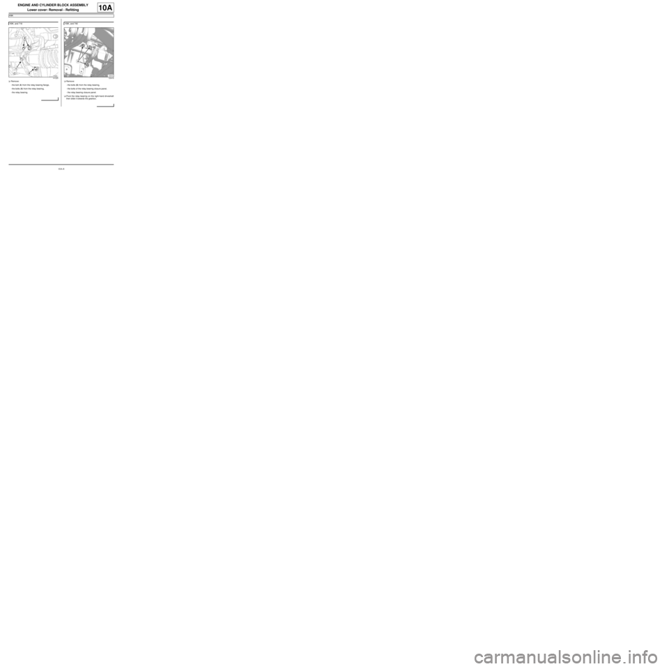
aRemove:
-the bolt (4) from the relay bearing flange,
-the bolts (5) from the relay bearing,
-the relay bearing.aRemove:
-the bolts (6) from the relay bearing,
-the bolts of the relay bearing closure panel,
-the relay bearing closure panel.
aPivot the relay bearing on the right-hand driveshaft
then slide it towards the gearbox. K9K, and 718
141225
K9K, and 740
120418
Page 16 of 652
10A-10
ENGINE AND CYLINDER BLOCK ASSEMBLY
Lower cover: Removal - Refitting
K9K
10A
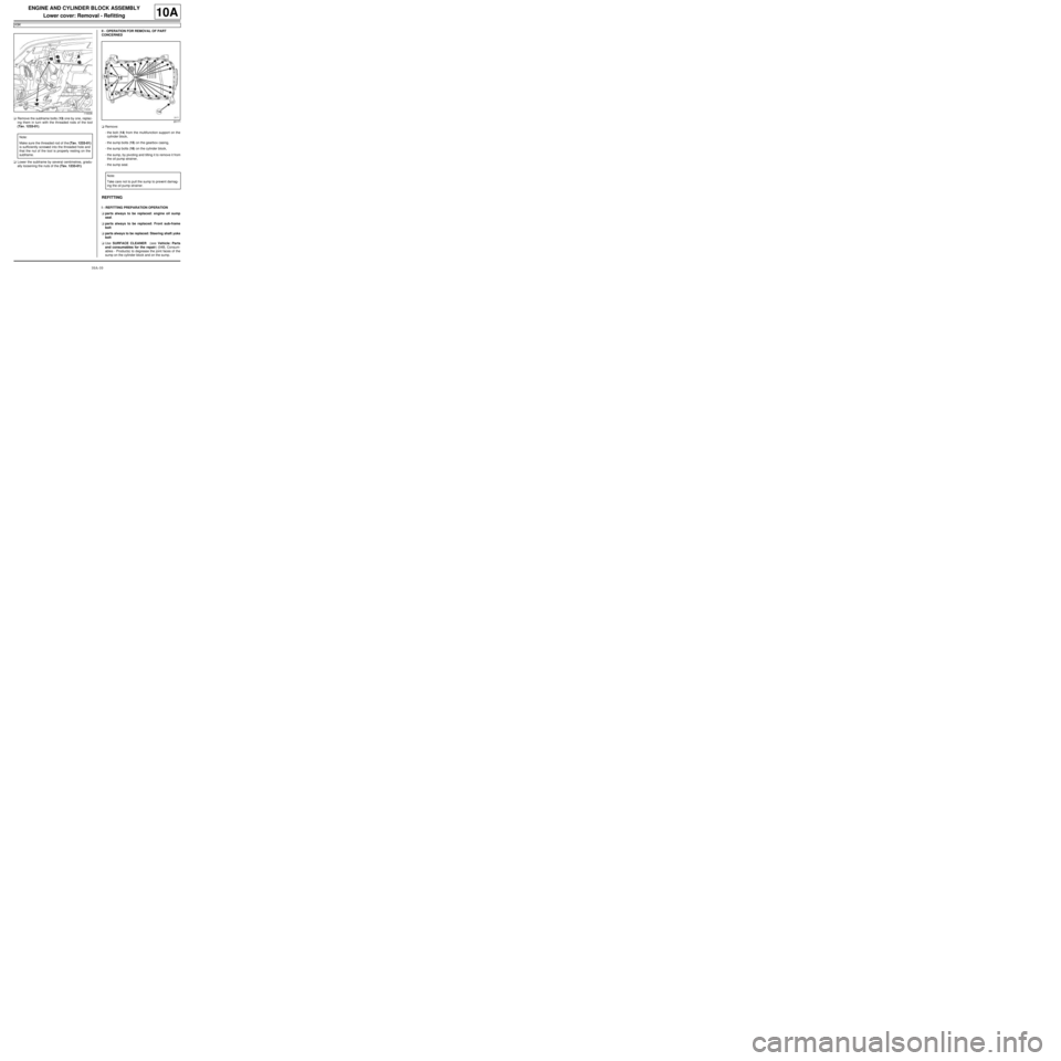
aRemove the subframe bolts (13) one by one, replac-
ing them in turn with the threaded rods of the tool
(Tav. 1233-01).
aLower the subframe by several centimetres, gradu-
ally loosening the nuts of the (Tav. 1233-01).II - OPERATION FOR REMOVAL OF PART
CONCERNED
aRemove:
-the bolt (14) from the multifunction support on the
cylinder block,
-the sump bolts (15) on the gearbox casing,
-the sump bolts (16) on the cylinder block,
-the sump, by pivoting and tilting it to remove it from
the oil pump strainer,
-the sump seal.
REFITTING
I - REFITTING PREPARATION OPERATION
aparts always to be replaced: engine oil sump
seal.
aparts always to be replaced: Front sub-frame
bolt
aparts always to be replaced: Steering shaft yoke
bolt
aUse SURFACE CLEANER (see Vehicle: Parts
and consumables for the repair) (04B, Consum-
ables - Products) to degrease the joint faces of the
sump on the cylinder block and on the sump.
119336
Note:
Make sure the threaded rod of the (Tav. 1233-01)
is sufficiently screwed into the threaded hole and
that the nut of the tool is properly resting on the
subframe.
20171
Note:
Take care not to pull the sump to prevent damag-
ing the oil pump str ainer.
Page 17 of 652
10A-11
ENGINE AND CYLINDER BLOCK ASSEMBLY
Lower cover: Removal - Refitting
K9K
10A
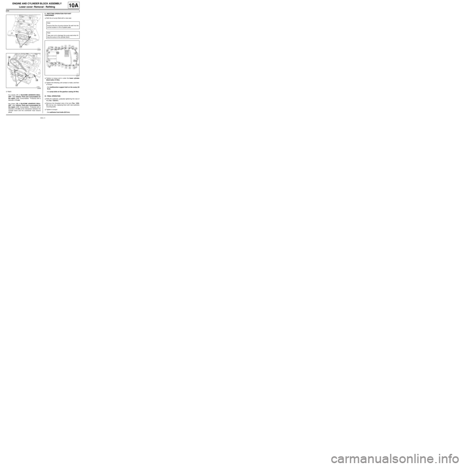
aApply:
-four beads (17) of SILICONE ADHESIVE SEAL-
ANT (see Vehicle: Parts and consumables for
the repair) (04B, Consumables - Products) with a
diameter of 5 mm,
-two drops (18) of SILICONE ADHESIVE SEAL-
ANT (see Vehicle: Parts and consumables for
the repair) (04B, Consumables - Products) with a
diameter of 5 mm at the intersection between the
cylinder block and the crankshaft nose closure
panel.II - REFITTING OPERATION FOR PART
CONCERNED
aRefit the oil sump fitted with a new seal.
aTighten to torque and in order the lower cylinder
block bolts (14 Nm).
aTighten the following until contact is made, and then
to torque:
-the multifunction support bolt on the sump (25
N.m).
-the sump bolts on the gearbox casing (44 Nm).
III - FINAL OPERATION
aRefit the subframe, gradually tightening the nuts of
the (Tav. 1233-01).
aRemove the threaded rods of the tool (Tav. 1233-
01) one by one, replacing them with new subframe
mounting bolts.
aTighten to torque:
-the subframe front bolts (62 N.m),
20167
20166
Note:
Ensure that the oil pump strainer fits well into the
correct location in the oil splash plate.
Note:
Take care not to damage the sump seal when fit-
ting the sump on the cylinder block.
20171
Page 25 of 652
10A-19
ENGINE AND CYLINDER BLOCK ASSEMBLY
Lower cover: Removal - Refitting
K4M
10A
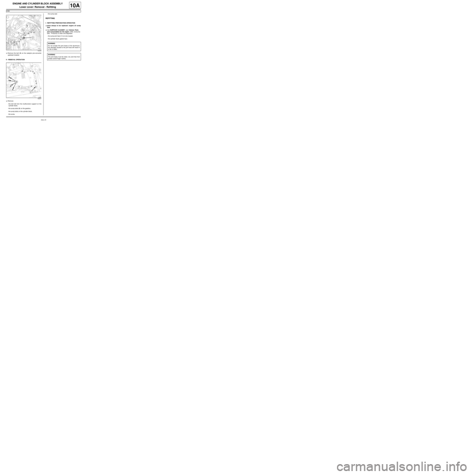
aRemove the bolt (3) on the catalytic pre-converter
upstream bracket.
II - REMOVAL OPERATION
aRemove:
-the bolt (4) from the multifunction support on the
cylinder block,
-the sump bolts (5) on the gearbox,
-the sump bolts on the cylinder block,
-the sump,-the sump seal.
REFITTING
I - REFITTING PREPARATION OPERATION
aparts always to be replaced: engine oil sump
seal.
aUse SURFACE CLEANER (see Vehicle: Parts
and consumables for the repair) (04B, Consuma-
bles - Products) to clean and degrease:
-the sump joint face if it is to be reused,
-the cylinder block gasket face.
132343
126231
WARNING
Do not scrape the joint faces of the aluminium,
any damage caused to the joint face will result in
a risk of leaks.
WARNING
The joint faces must be clean, dr y and free from
grease (avoid finger marks).
Page 26 of 652
10A-20
ENGINE AND CYLINDER BLOCK ASSEMBLY
Lower cover: Removal - Refitting
K4M
10A
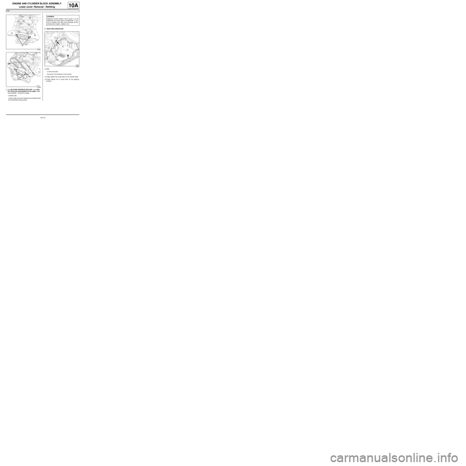
aUse SILICONE ADHESIVE SEALANT (see Vehi-
cle: Parts and consumables for the repair) (04B,
Consumables - Products) to apply:
-a bead at (4) ,
-a drop at (5) at the joint between the cylinder block
and crankshaft closure panel.II - REFITTING OPERATION
aRefit:
-a new sump seal,
-the sump in the direction of the arrows.
aFinger tighten the sump bolts on the cylinder block.
aFinger tighten the 4 sump bolts on the gearbox
housing.
20167
20166
WARNING
Applying excess sealant could cause it to be
squeezed out when parts are tightened. A mix-
ture of sealant and fluid could damage certain
components (engine, radiator, etc.).
145657
Page 27 of 652
10A-21
ENGINE AND CYLINDER BLOCK ASSEMBLY
Lower cover: Removal - Refitting
K4M
10A
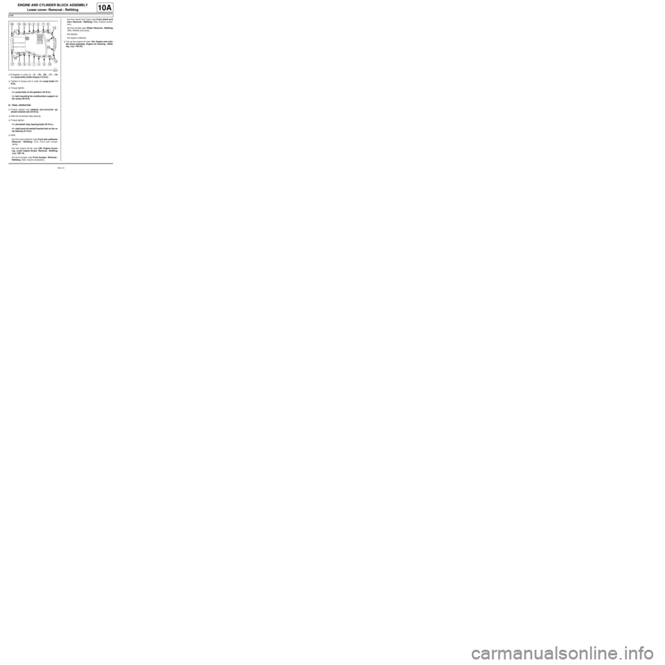
aPretighten in order (1) , (2) , (19) , (20) , (17) , (18)
the sump bolts (initial torque) (14 N.m).
aTighten to torque and in order the sump bolts (14
N.m).
aTorque tighten:
-the sump bolts on the gearbox (44 N.m),
-the bolt mounting the multifunction support on
the sump (25 N.m).
III - FINAL OPERATION
aTorque tighten the catalytic pre-converter up-
stream bracket bolt (44 N.m).
aRefit the driveshaft relay bearing.
aTorque tighten:
-the driveshaft relay bearing bolts (44 N.m.),
-the right-hand driveshaft bracket bolt on the re-
lay bearing (21 N.m).
aRefit:
-the front axle subframe (see Front axle subframe:
Removal - Refitting) (31A, Front axle compo-
nents),
-the rear engine tie-bar (see 19D, Engine mount-
ing, Lower engine tie-bar: Removal - Refitting,
page 19D-18) ,
-the front bumper (see Front bumper: Removal -
Refitting) (55A, Exterior protection),-the front wheel arch liners (see Front wheel arch
liner: Removal - Refitting) (55A, Exterior protec-
tion),
-the front wheels (see Wheel: Removal - Refitting)
(35A, Wheels and tyres),
-the dipstick,
-the engine undertray.
aTop up the engine oil (see 10A, Engine and cylin-
der block assembly, Engine oil: Draining - Refill-
ing, page 10A-22) .
20171