light RENAULT TWINGO 2009 2.G Engine And Peripherals Service Manual
[x] Cancel search | Manufacturer: RENAULT, Model Year: 2009, Model line: TWINGO, Model: RENAULT TWINGO 2009 2.GPages: 652
Page 402 of 652
13B-41
DIESEL INJECTION
High pressure pipe between rail and injector: Removal - Refitting
K9K
13B
II - OPERATION FOR REMOVAL OF PART
CONCERNED
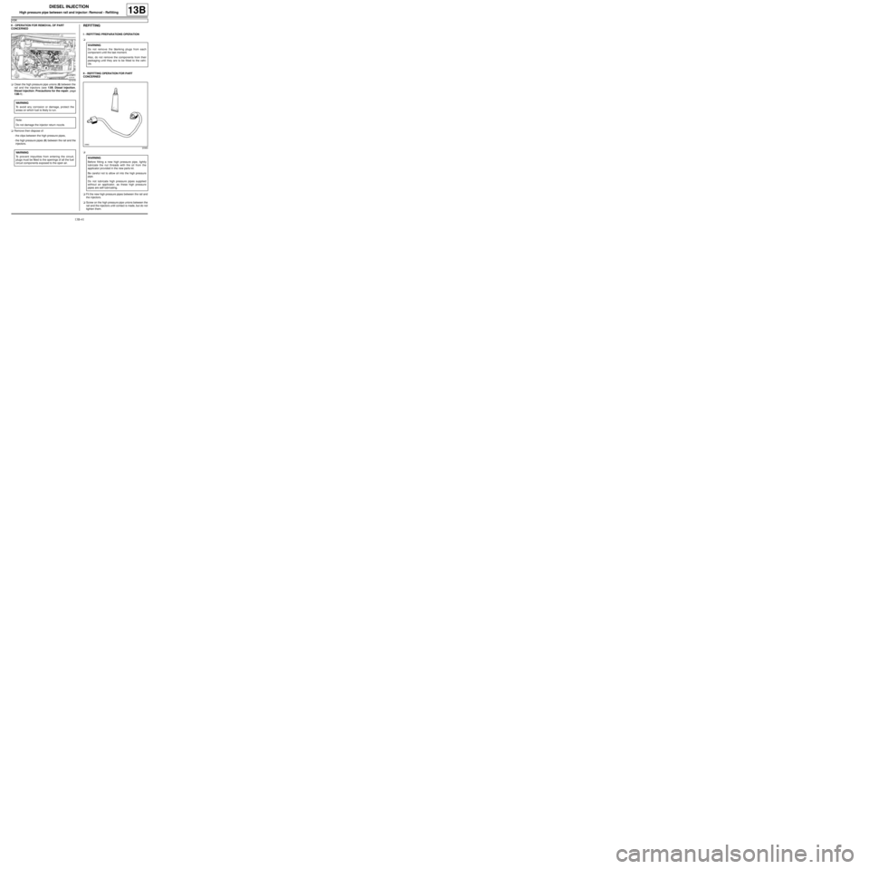
aClean the high pressure pipe unions (6) between the
rail and the injectors (see 13B, Diesel injection,
Diesel injection: Precautions for the repair, page
13B-1) .
aRemove then dispose of:
-the clips between the high pressure pipes,
-the high pressure pipes (6) between the rail and the
injectors.REFITTING
I - REFITTING PREPARATIONS OPERATION
a
II - REFITTING OPERATION FOR PART
CONCERNED
a
aFit the new high pressure pipes between the rail and
the injectors.
aScrew on the high pressure pipe unions between the
rail and the injectors until contact is made, but do not
tighten them.
121418
WARNING
To avoid any corrosion or damage, protect the
areas on which fuel is likely to run.
Note:
Do not damage the injector return nozzle.
WARNING
To prevent impurities from entering the circuit,
plugs must be fitted to the openings of all the fuel
circuit components exposed to the open air.
WARNING
Do not remove the blanking plugs from each
component until the last moment.
Also, do not remove the components from their
packaging until they are to be fitted to the vehi-
cle.
20960
WARNING
Before fitting a new high pressure pipe, lightly
lubricate the nut threads with the oil from the
applicator provided in the new parts kit.
Be careful not to allow oil into the high pressure
pipe.
Do not lubricate high pressure pipes supplied
without an applicator, as these high pressure
pipes are self-lubr icating.
Page 408 of 652
13B-47
DIESEL INJECTION
Injector rail: Removal - Refitting
K9K
13B
aRemove the blanking plugs.
aFit the injector rail.
aFit the injector rail nuts without tightening them.
III - FINAL OPERATION.
a
aRemove the blanking plugs from the high pressure
pump and the injection rail and discard them.
aFit the high pressure pipe between the high pressure
pump and the injection rail.
aTighten the high pressure pipe unions between the
pump and the rail until contact is made.
aRemove the blanking plugs on the injection rail and
the diesel fuel injectors then discard them.
aFit the new high-pressure pipes between the rail and
the injectors.
aTighten until contact the unions of the high pressure
pipes between the rail and injector.aFit and lock the new clips between the high pressure
pipes on the rail and injectors.
aTighten to torque:
-the injector rail nuts (28 Nm),
-the unions for the high pressure pipes between
the rail and the yellow-coloured injector (24
Nm) using the tool (Mot. 1746),
-the unions for the high pressure pipes between
the rail and the silver-coloured injector (28 Nm)
using the tool (Mot. 1746),
-the unions for the high pressure pipes between
the pump and the yellow-coloured rail (24 Nm)
using the tool (Mot. 1746),
-the unions for the high pressure pipes between
the pump and the silver-coloured rail (28 Nm)
using the tool (Mot. 1746),
aConnect to the high pressure pump:
-the fuel return pipe to the fuel filter,
-the fuel supply pipe.
aRefit the neck on the injection rail.
aRemove the protection fitted on the inlet opening of
the oil level dipstick on the cylinder block.
aRefit:
-the dipstick guide,
-the oil level dipstick nut,
-the oil level dipstick.
aConnect the injector rail pressure sensor connector.
aPosition the wiring harness in its channel.
aFasten the electrical wiring to the channel.
aConnect:
-the diesel temperature sensor,
-the fuel flow actuator,
-the injector connectors,
-the heater plug connectors.
aPrime the fuel circuit using a manual priming pump
until the disconnected pipes are filled with fuel.
aCheck that there are no fuel leaks.
aConnect the battery (see Battery: Removal - Refit-
ting) (80A, Battery).
aCheck the high pressure circuit (see 13B, Diesel in-
jection, High pressure pipe: Check, page 13B-34)
.
aRefit the engine cover.
20960
WARNING
Before fitting a new high-pressure pipe, lightly
lubricate the nut threads with the oil from the
applicator provided in the new parts kit.
Be careful not to allow oil into the high-pressure
pipe.
Do not lubricate high-pressure pipes supplied
without an applicator, as these high-pressure
pipes are self-lubricating.
Page 446 of 652
16A-7
STARTING - CHARGING
Alternator: Removal - Refitting
K4M
16A
REMOVAL
I - REMOVAL PREPARATION OPERATION
aPosition the vehicle on a two-post lift (see Vehicle:
Towing and lifting) (02A, Lifting equipment).
aDisconnect the battery (see Battery: Removal - Re-
fitting) (80A, Battery).
aRemove:
-the engine undertray,
-the front right-hand wheel (see Wheel: Removal -
Refitting) (35A, Wheels and tyres),
-the front right-hand wheel arch liner (see Front
wheel arch liner: Removal - Refitting) (55A, Ex-
terior protection),
-the front bumper (see Front bumper: Removal -
Refitting) (55A, Exterior protection),
-the headlights (see Halogen headlight: Removal
- Refitting) (80B, Headlights),
-the bonnet catch (see Bonnet lock: Removal -
Refitting) (52A, Non-side opening element mecha-
nisms),
-the front upper cross member (see Front upper
cross member: Removal - Refitting) (42A, Upper
front structure),
-the accessories belt (see 11A, Top and front of
engine, Accessories belt: Removal - Refitting,
page 11A-3) .II - REMOVAL OPERATION
aRemove:
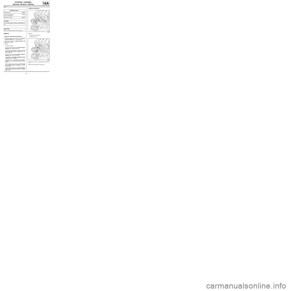
-the alternator strut bolts (1) ,
-the alternator strut.
aRemove the nut (2) on the alternator positive termi-
nal.
aDisconnect the alternator connector (3) . Tightening torquesm
alter nator bolts25 N.m
nut for the positive ter-
minal of the alternator21 N.m
alter nator strut bolts25 N.m
WARNING
Do not r un the engine without the accessories belt
to avoid damaging the crankshaft accessories pul-
ley.
IMPORTANT
Wear cut-resistant gloves during the operation.
132363
132365
Page 448 of 652
16A-9
STARTING - CHARGING
Alternator: Removal - Refitting
K4M
16A
aRefit the alternator strut.
aTighten to torque and in order the alternator strut
bolts (25 N.m).
III - FINAL OPERATION
aRefit:
-the accessories belt (see 11A, Top and front of
engine, Accessories belt: Removal - Refitting,
page 11A-3) ,
-the front upper cross member (see Front upper
cross member: Removal - Refitting) (42A, Upper
front structure),
-the bonnet catch (see Bonnet lock: Removal -
Refitting) (52A, Non-side opening element mecha-
nisms),
-the headlights (see Halogen headlight: Removal
- Refitting) (80B, Headlights),
-the front bumper (see Front bumper: Removal -
Refitting) (55A, Exterior protection),
-the front right-hand wheel arch liner (see Front
wheel arch liner: Removal - Refitting) (55A, Ex-
terior protection),
-the front right-hand wheel (see Wheel: Removal -
Refitting) (35A, Wheels and tyres),
-the engine undertray.
aConnect the battery (see Battery: Removal - Refit-
ting) (80A, Battery).
132363
Page 537 of 652
19A-27
COOLING
Coolant pump: Removal - Refitting
K9K
19A
REMOVAL
I - REMOVAL PREPARATION OPERATION
aPosition the vehicle on a two-post lift (see Vehicle:
Towing and lifting) (02A, Lifting equipment).
aDisconnect the battery (see Battery: Removal - Re-
fitting) (80A, Battery).
aRemove:
-the windscreen wiper arms (see Windscreen wip-
er arm: Removal - Refitting) (85A, Wiping -
Washing),
-the scuttle panel grille (see Scuttle panel grille:
Removal - Refitting) (56A, Exterior equipment),
-the scoop under the scuttle panel grille (see Scoop
under the scuttle panel grille: Removal - Refit-
ting) (56A, Exterior equipment),
-the front right-hand wheel (see Wheel: Removal -
Refitting) (35A, Wheels and tyres),
-the front right-hand wheel arch liner (see Front
wheel arch liner: Removal - Refitting) (55A, Ex-
terior protection),
-the front bumper (see Front bumper: Removal -
Refitting) (55A, Exterior protection),
-the halogen headlights (see Halogen headlight:
Removal - Refitting) (80B, Headlights),
-the front upper cross member (see Front upper
cross member: Removal - Refitting) (42A, Upper
front structure),-the lower engine tie-bar (see 19D, Engine mount-
ing, Lower engine tie-bar: Removal - Refitting,
page 19D-18) ,
-the right-hand suspended engine mounting (see
19D, Engine mounting, Right-hand suspended
engine mounting: Removal - Refitting, page
19D-13) ,
-the accessories belt (see 11A, Top and front of
engine, Accessories belt: Removal - Refitting,
page 11A-3) ,
-the crankshaft accessories pulley (see 11A, Top
and front of engine, Crankshaft accessories
pulley: Removal - Refitting, page 11A-20) ,
-the camshaft position sensor (see 13B, Diesel in-
jection, Camshaft position sensor: Removal -
Refitting, page 13B-14) ,
-the timing belt (see 11A, Top and front of engine,
Timing belt: Removal - Refitting, page 11A-27) .
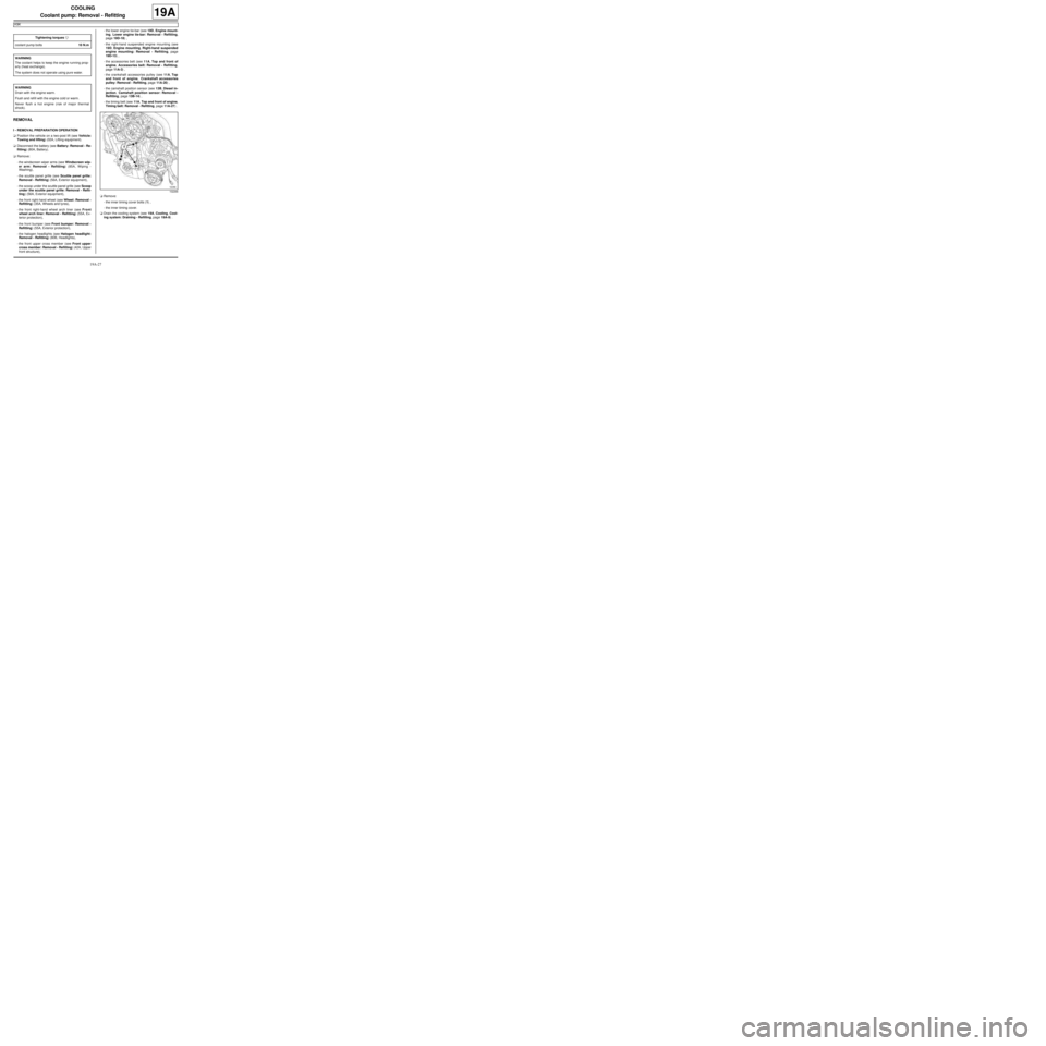
aRemove:
-the inner timing cover bolts (1) ,
-the inner timing cover.
aDrain the cooling system (see 19A, Cooling, Cool-
ing system: Draining - Refilling, page 19A-9) . Tightening torquesm
coolant pump bolts10 N.m
WARNING
The coolant helps to keep the engine running prop-
erly (heat exchange).
The system does not operate using pure water.
WARNING
Drain with the engine warm.
Flush and refill with the engine cold or warm.
Never flush a hot engine (risk of major thermal
shock).
102266
Page 539 of 652
19A-29
COOLING
Coolant pump: Removal - Refitting
K9K
19A
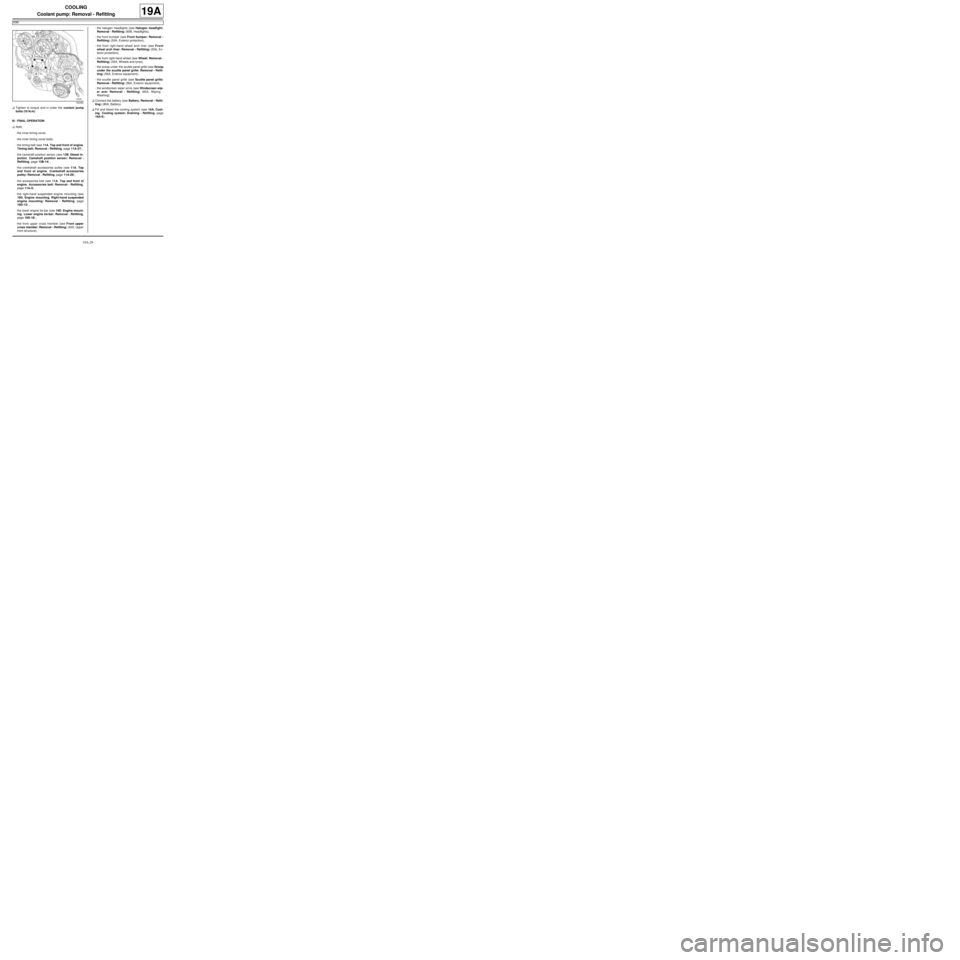
aTighten to torque and in order the coolant pump
bolts (10 N.m).
III - FINAL OPERATION
aRefit:
-the inner timing cover,
-the inner timing cover bolts,
-the timing belt (see 11A, Top and front of engine,
Timing belt: Removal - Refitting, page 11A-27) ,
-the camshaft position sensor (see 13B, Diesel in-
jection, Camshaft position sensor: Removal -
Refitting, page 13B-14) ,
-the crankshaft accessories pulley (see 11A, Top
and front of engine, Crankshaft accessories
pulley: Removal - Refitting, page 11A-20) ,
-the accessories belt (see 11A, Top and front of
engine, Accessories belt: Removal - Refitting,
page 11A-3) ,
-the right-hand suspended engine mounting (see
19D, Engine mounting, Right-hand suspended
engine mounting: Removal - Refitting, page
19D-13) ,
-the lower engine tie-bar (see 19D, Engine mount-
ing, Lower engine tie-bar: Removal - Refitting,
page 19D-18) ,
-the front upper cross member (see Front upper
cross member: Removal - Refitting) (42A, Upper
front structure),-the halogen headlights (see Halogen headlight:
Removal - Refitting) (80B, Headlights),
-the front bumper (see Front bumper: Removal -
Refitting) (55A, Exterior protection),
-the front right-hand wheel arch liner (see Front
wheel arch liner: Removal - Refitting) (55A, Ex-
terior protection),
-the front right-hand wheel (see Wheel: Removal -
Refitting) (35A, Wheels and tyres),
-the scoop under the scuttle panel grille (see Scoop
under the scuttle panel grille: Removal - Refit-
ting) (56A, Exterior equipment),
-the scuttle panel grille (see Scuttle panel grille:
Removal - Refitting) (56A, Exterior equipment),
-the windscreen wiper arms (see Windscreen wip-
er arm: Removal - Refitting) (85A, Wiping -
Washing).
aConnect the battery (see Battery: Removal - Refit-
ting) (80A, Battery).
aFill and bleed the cooling system (see 19A, Cool-
ing, Cooling system: Draining - Refilling, page
19A-9) .
102262
Page 540 of 652
19A-30
COOLING
Coolant pump: Removal - Refitting
K4M
19A
REMOVAL
I - REMOVAL PREPARATION OPERATION
aPosition the vehicle on a two-post lift (see Vehicle:
Towing and lifting) (02A, Lifting equipment).
aDrain the cooling system (see 19A, Cooling, Cool-
ing system: Draining - Refilling, page 19A-9) .
aDisconnect the battery (see Battery: Removal - Re-
fitting) (80A, Battery).aRemove:
-the engine undertray,
-the front right-hand wheel (see Wheel: Removal -
Refitting) (35A, Wheels and tyres),
-the front right-hand wheel arch liner (see Front
wheel arch liner: Removal - Refitting) (55A, Ex-
terior protection),
-the front bumper (see Front bumper: Removal -
Refitting) (55A, Exterior protection),
-the headlights (see Halogen headlight: Removal
- Refitting) (80B, Headlights),
-the bonnet catch (see Bonnet lock: Removal -
Refitting) (52A, Non-side opening element mecha-
nisms),
-the front upper cross member (see Front upper
cross member: Removal - Refitting) (42A, Upper
front structure),
-the accessories belt (see 11A, Top and front of
engine, Accessories belt: Removal - Refitting,
page 11A-3) ,
-the air filter unit (see 12A, Fuel mixture, Air filter
unit: Removal - Refitting, page 12A-13) ,
-the throttle valve (see 12A, Fuel mixture, Throttle
valve: Removal - Refitting, page 12A-20) ,
-the windscreen wiper arms (see Windscreen wip-
er arm: Removal - Refitting) (85A, Wiping -
Washing),
-the scuttle panel grille (see Scuttle panel grille:
Removal - Refitting) (56A, Exterior equipment),
-the scoop under the scuttle panel grille (see Scoop
under the scuttle panel grille: Removal - Refit-
ting) (56A, Exterior equipment),
-the right-hand suspended engine mounting (see
19D, Engine mounting, Right-hand suspended
engine mounting: Removal - Refitting, page
19D-13) ,
-the crankshaft accessories pulley (see 11A, Top
and front of engine, Crankshaft accessories
pulley: Removal - Refitting, page 11A-20) ,
-the timing belt (see 11A, Top and front of engine,
Timing belt: Removal - Refitting, page 11A-27) ,
-the camshaft dephaser (see 11A, Top and front of
engine, Camshaft dephaser: Removal - Refit-
ting, page 11A-135) . Tightening torquesm
bolt 1 of the coolant
pump27 N.m
bolts 2 to 8 of the water
pump10 N.m
IMPORTANT
When working in the engine compartment, take
care as the radiator fan(s) may start up unexpect-
edly (risk of being cut).
To avoid any risk of serious burns when the engine
is hot:
-do not open the expansion bottle cap,
-do not drain the cooling system,
-do not open the bleed screw(s).
WARNING
Prepare for the flow of fluid, and protect the sur-
rounding components.
WARNING
When carr ying out a repair that requires a complete
change, it is essential to flush the circuit with clean
water, blast compressed air through the circuit to
drive out the water, fill and bleed the circuit and
then measure the effective protection.
The cr iteria to be met are:
-protection down to -25˚C ±± ± ±
2 for cold and temper-
ate countries,
-protection down to -40˚C ±± ± ±
2 for "extreme cold"
countries.
Page 543 of 652
19A-33
COOLING
Coolant pump: Removal - Refitting
K4M
19A
-the scoop under the scuttle panel grille (see Scoop
under the scuttle panel grille: Removal - Refit-
ting) (56A, Exterior equipment),
-the scuttle panel grille (see Scuttle panel grille:
Removal - Refitting) (56A, Exterior equipment),
-the windscreen wiper arms (see Windscreen wip-
er arm: Removal - Refitting) (85A, Wiping -
Washing),
-the throttle valve (see 12A, Fuel mixture, Throttle
valve: Removal - Refitting, page 12A-20) ,
-the air filter unit (see 12A, Fuel mixture, Air filter
unit: Removal - Refitting, page 12A-13) ,
-the accessories belt (see 11A, Top and front of
engine, Accessories belt: Removal - Refitting,
page 11A-3) ,
-the front upper cross member (see Front upper
cross member: Removal - Refitting) (42A, Upper
front structure),
-the bonnet catch (see Bonnet lock: Removal -
Refitting) (52A, Non-side opening element mecha-
nisms),
-the headlights (see Halogen headlight: Removal
- Refitting) (80B, Headlights),
-the front bumper (see Front bumper: Removal -
Refitting) (55A, Exterior protection),
-the front right-hand wheel arch liner (see Front
wheel arch liner: Removal - Refitting) (55A, Ex-
terior protection),
-the front right-hand wheel (see Wheel: Removal -
Refitting) (35A, Wheels and tyres).
aConnect the battery (see Battery: Removal - Refit-
ting) (80A, Battery).
aFill and bleed the cooling system (see 19A, Cool-
ing, Cooling system: Draining - Refilling, page
19A-9) .
aRefit the engine undertray.
Page 561 of 652
19A-51
COOLING
Engine cooling fan assembly: Removal - Refitting
C44, and K9K
19A
REMOVAL
I - REMOVAL PREPARATION OPERATION
aPosition the vehicle on a two-post lift ( (see Vehicle:
Towing and lifting) )
aDisconnect the battery ( (see Battery: Removal -
Refitting) ).
aRemove:
-the engine undertray bolts,
-the engine undertray,
-the front bumper ( (see Front bumper: Removal -
Refitting) ),
-the left-hand and right-hand headlights (see Halo-
gen headlight: Removal - Refitting) .
aRemove:
-the cooling radiator retaining lug bolt,
-the expansion bottle bolt onto the front upper cross
member,
-the air filter inlet air pipe bolt on the front upper
cross member.
aUnclip and then remove from the front upper cross
member:
-the air filter inlet air pipe,
-the expansion bottle.
aRemove the bonnet lock nuts.
aRemove the « cable - bonnet catch » assembly.
aRemove the front upper cross member ( (see Front
upper cross member: Removal - Refitting) )
II - OPERATION FOR REMOVAL OF PART
CONCERNED
aDisconnect the electrical connectors on the engine
cooling fan assembly.
aUnclip:
-the engine cooling fan assembly wiring,
-the coolant hose at the bottom of the engine cool-
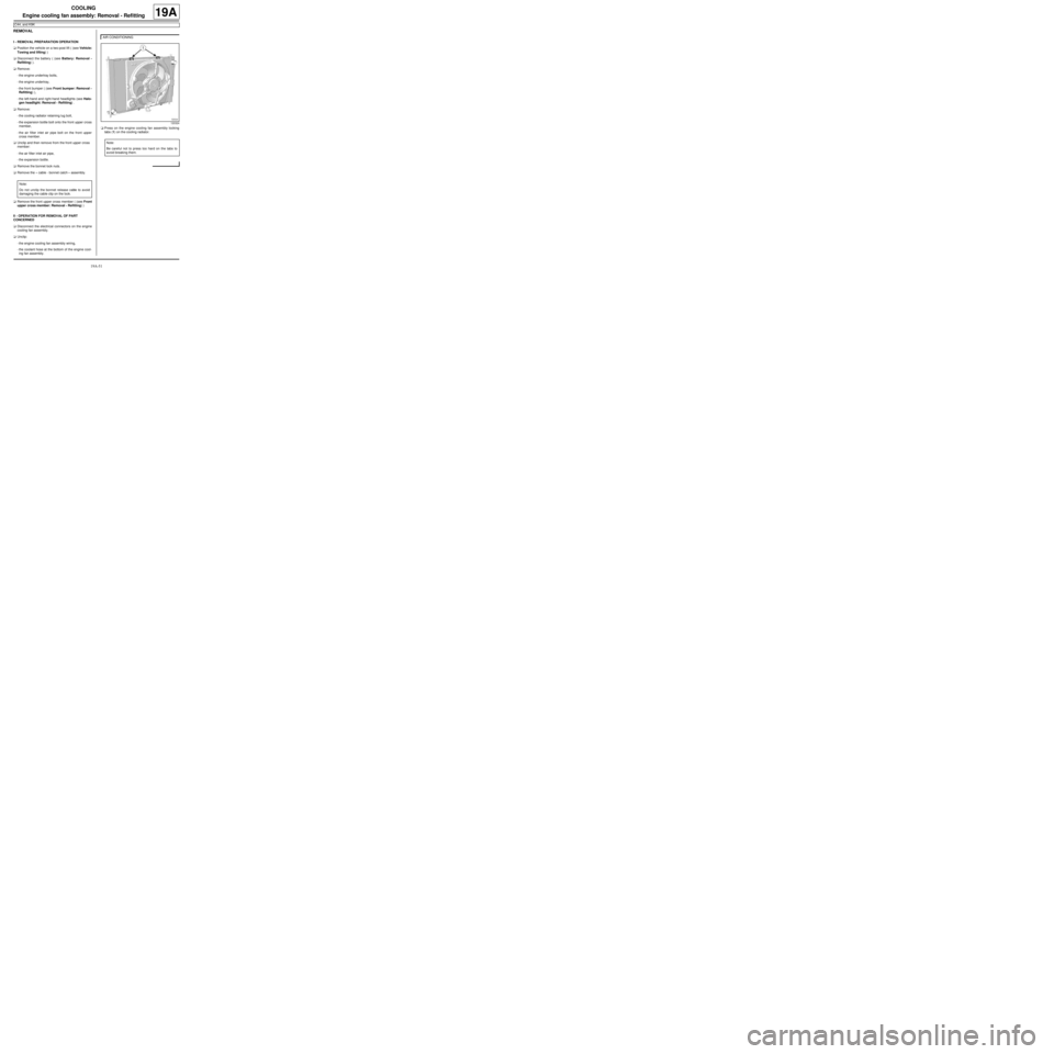
ing fan assembly.aPress on the engine cooling fan assembly locking
tabs (1) on the cooling radiator.
Note:
Do not unclip the bonnet release cable to avoid
damaging the cable clip on the lock.
AIR CONDITIONING
120324
Note:
Be careful not to press too hard on the tabs to
avoid breaking them.
Page 562 of 652
19A-52
COOLING
Engine cooling fan assembly: Removal - Refitting
C44, and K9K
19A
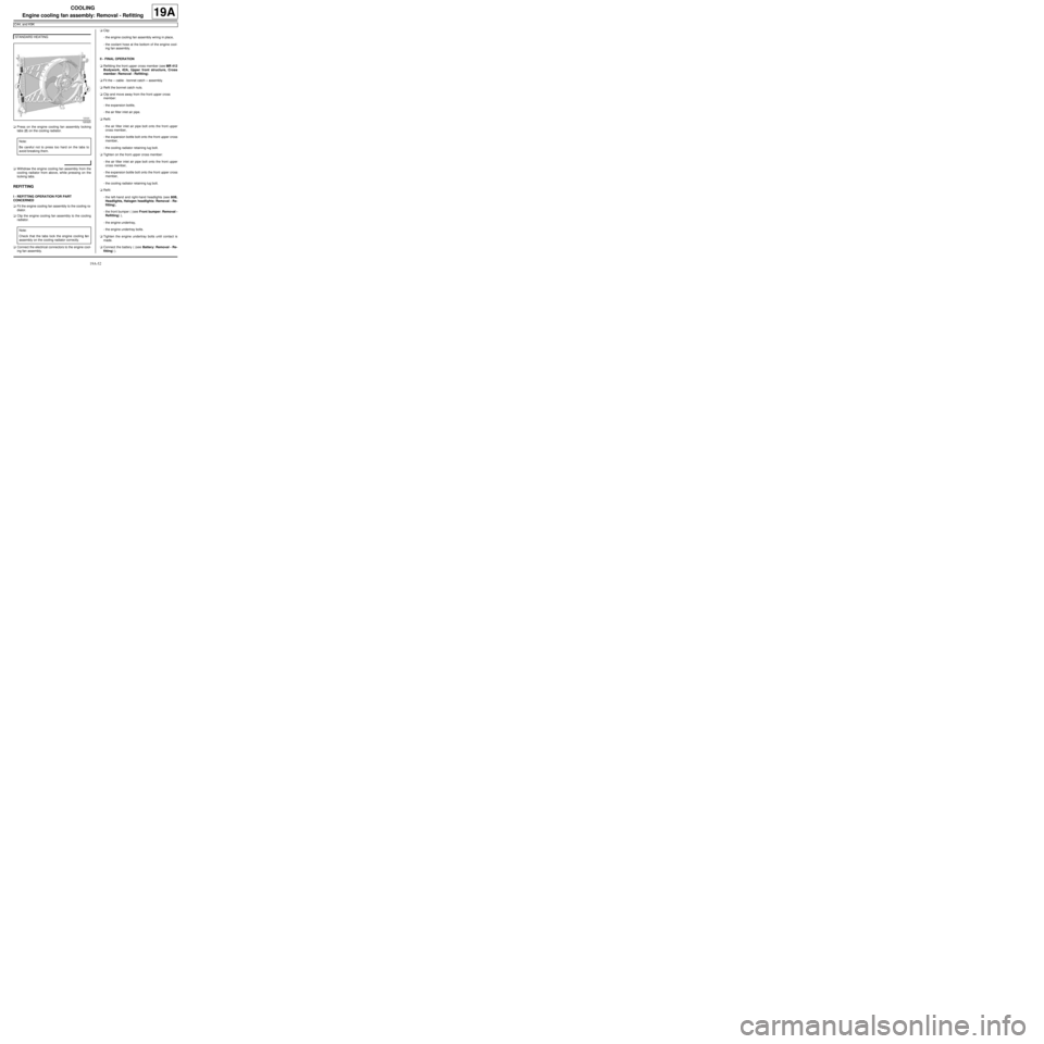
aPress on the engine cooling fan assembly locking
tabs (2) on the cooling radiator.
aWithdraw the engine cooling fan assembly from the
cooling radiator from above, while pressing on the
locking tabs.
REFITTING
I - REFITTING OPERATION FOR PART
CONCERNED
aFit the engine cooling fan assembly to the cooling ra-
diator.
aClip the engine cooling fan assembly to the cooling
radiator.
aConnect the electrical connectors to the engine cool-
ing fan assembly.aClip:
-the engine cooling fan assembly wiring in place,
-the coolant hose at the bottom of the engine cool-
ing fan assembly.
II - FINAL OPERATION
aRefitting the front upper cross member (see MR 412
Bodywork, 42A, Upper front structure, Cross
member: Removal - Refitting).
aFit the « cable - bonnet catch » assembly.
aRefit the bonnet catch nuts.
aClip and move away from the front upper cross
member:
-the expansion bottle,
-the air filter inlet air pipe.
aRefit:
-the air filter inlet air pipe bolt onto the front upper
cross member,
-the expansion bottle bolt onto the front upper cross
member,
-the cooling radiator retaining lug bolt.
aTighten on the front upper cross member:
-the air filter inlet air pipe bolt onto the front upper
cross member,
-the expansion bottle bolt onto the front upper cross
member,
-the cooling radiator retaining lug bolt.
aRefit:
-the left-hand and right-hand headlights (see 80B,
Headlights, Halogen headlights: Removal - Re-
fitting),
-the front bumper ( (see Front bumper: Removal -
Refitting) ),
-the engine undertray,
-the engine undertray bolts.
aTighten the engine undertray bolts until contact is
made.
aConnect the battery ( (see Battery: Removal - Re-
fitting) ). STANDARD HEATING
120325
Note:
Be careful not to press too hard on the tabs to
avoid breaking them.
Note:
Check that the tabs lock the engine cooling fan
assembly on the cooling radiator correctly.