Intake RENAULT TWINGO 2009 2.G Engine And Peripherals Workshop Manual
[x] Cancel search | Manufacturer: RENAULT, Model Year: 2009, Model line: TWINGO, Model: RENAULT TWINGO 2009 2.GPages: 652
Page 183 of 652
11A-66
TOP AND FRONT OF ENGINE
Rocker cover: Removal - Refitting
D7F
11A
REMOVAL
I - REMOVAL PREPARATION OPERATION
aDisconnect the battery ( (see Battery: Removal -
Refitting) ).
aRemove:
-the intake distributor (see 12A, Fuel mixture, Inlet
distributor: Removal - Refitting, page 12A-29) ,
-the air filter box (see 12A, Fuel mixture, Air filter
unit: Removal - Refitting, page 12A-13) .
aUnclip:
-The harness from the heat shield,
-the brake servo pipe from the heat shield.
aDisconnect the ignition coil supply.
II - OPERATION FOR REMOVAL OF PART
CONCERNED
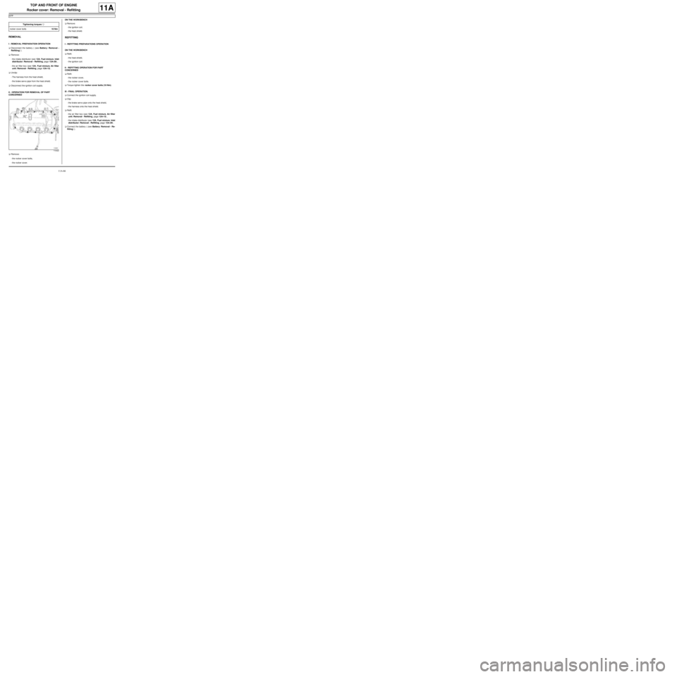
aRemove:
-the rocker cover bolts,
-the rocker cover.ON THE WORKBENCH
aRemove:
-the ignition coil,
-the heat shield.
REFITTING
I - REFITTING PREPARATIONS OPERATION
ON THE WORKBENCH
aRefit:
-the heat shield,
-the ignition coil.
II - REFITTING OPERATION FOR PART
CONCERNED
aRefit:
-the rocker cover,
-the rocker cover bolts.
aTorque tighten the rocker cover bolts (10 Nm).
III - FINAL OPERATION.
aConnect the ignition coil supply.
aClip:
-the brake servo pipe onto the heat shield,
-the harness onto the heat shield.
aRefit:
-the air filter box (see 12A, Fuel mixture, Air filter
unit: Removal - Refitting, page 12A-13) ,
-the intake distributor (see 12A, Fuel mixture, Inlet
distributor: Removal - Refitting, page 12A-29) .
aConnect the battery ( (see Battery: Removal - Re-
fitting) ). Tightening torquesm
rocker cover bolts10 Nm
110422
Page 219 of 652
11A-102
TOP AND FRONT OF ENGINE
Camshaft: Removal - Refitting
D7F
11A
REMOVAL
I - REMOVAL PREPARATION OPERATION
aPosition the vehicle on a two-post lift (see Vehicle:
Towing and lifting) (02A, Lifting equipment).
aDisconnect the battery (see Battery: Removal - Re-
fitting) (80A, Battery).
aPerform the following operations:
-drain the engine oil (see 10A, Engine and cylin-
der block assembly, Engine oil: Draining - Re-
filling, page 10A-22) ,
-drain the cooling system (see 19A, Cooling, Cool-
ing system: Draining - Refilling, page 19A-9) .
aRemove:
-the front right-hand wheel (see Wheel: Removal -
Refitting) (35A, Wheels and tyres),
-the front right-hand wheel arch liner (see Front
wheel arch liner: Removal - Refitting) (55A, Ex-
terior protection),
-the ignition coil (see 17A, Ignition, Coils: Remov-
al - Refitting, page 17A-1) ,
-the air filter box (see 12A, Fuel mixture, Air filter
unit: Removal - Refitting, page 12A-13) ,
-the accessories belt (see 11A, Top and front of
engine, Accessories belt: Removal - Refitting,
page 11A-3) ,-the right-hand suspended engine mounting (see
19D, Engine mounting, Right-hand suspended
engine mounting: Removal - Refitting, page
19D-13) ,
-the crankshaft accessories pulley (see 11A, Top
and front of engine, Crankshaft accessories
pulley: Removal - Refitting, page 11A-20) ,
-the timing belt (see 11A, Top and front of engine,
Timing belt: Removal - Refitting, page 11A-27) ,
-the intake distributor (see 12A, Fuel mixture, Inlet
distributor: Removal - Refitting, page 12A-29) ,
-the rocker cover (see 11A, Top and front of en-
gine, Rocker cover: Removal - Refitting, page
11A-66) .
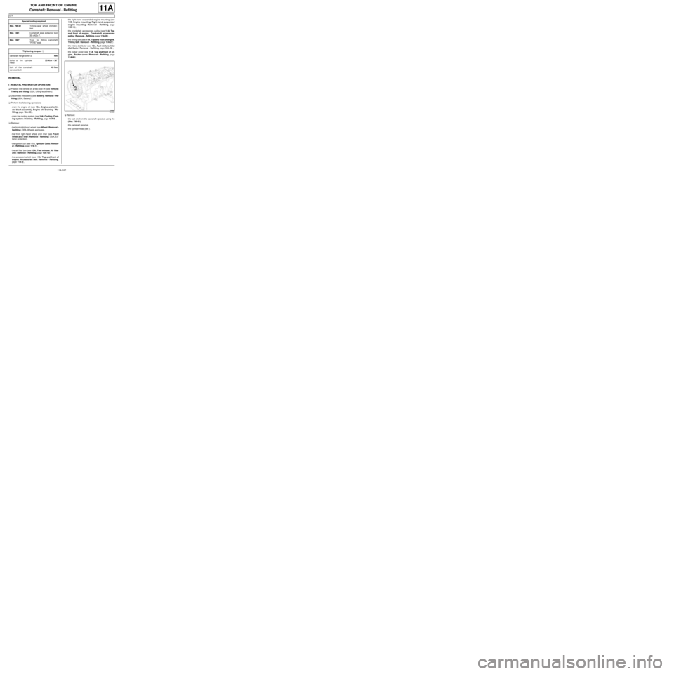
aRemove:
-the bolt (1) from the camshaft sprocket using the
(Mot. 799-01),
-the camshaft sprocket,
-the cylinder head (see ) . Special tooling required
Mot. 799-01Timing gear wheel immobil-
iser.
Mot. 1381Camshaft seal extractor tool
30 x 42 x 7.
Mot. 1587Tool for fitting camshaft
"PTFE" seal.
Tightening torquesm
camshaft flange bolts12Nm
bolts of the cylinder
head23 N.m + 36˚
bolt of the camshaft
sprocket bolt45 Nm
124822
Page 223 of 652
11A-106
TOP AND FRONT OF ENGINE
Camshaft: Removal - Refitting
D7F
11A
aRefit:
-the cylinder head (see ) ,
-the rocker cover (see 11A, Top and front of en-
gine, Rocker cover: Removal - Refitting, page
11A-66) ,
-the intake distributor (see 12A, Fuel mixture, Inlet
distributor: Removal - Refitting, page 12A-29) ,
-the timing belt (see 11A, Top and front of engine,
Timing belt: Removal - Refitting, page 11A-27) ,
-the crankshaft accessories pulley (see 11A, Top
and front of engine, Crankshaft accessories
pulley: Removal - Refitting, page 11A-20) ,
-the right-hand suspended engine mounting (see
19D, Engine mounting, Right-hand suspended
engine mounting: Removal - Refitting, page
19D-13) ,
-the accessories belt (see 11A, Top and front of
engine, Accessories belt: Removal - Refitting,
page 11A-3) ,
-the air filter box (see 12A, Fuel mixture, Air filter
unit: Removal - Refitting, page 12A-13) ,
-the ignition coil (see 17A, Ignition, Coils: Remov-
al - Refitting, page 17A-1) ,
-the front right-hand wheel arch liner (see Front
wheel arch liner: Removal - Refitting) (55A, Ex-
terior protection),
-the front right-hand wheel (see Wheel: Removal -
Refitting) (35A, Wheels and tyres).
aConnect the battery (see Battery: Removal - Refit-
ting) (80A, Battery).
aPerform the following operations:
-top up the engine oil (see 10A, Engine and cylin-
der block assembly, Engine oil: Draining - Re-
filling, page 10A-22) ,
-fill and bleed the coolant circuit (see 19A, Cooling,
Cooling system: Draining - Refilling, page 19A-
9) .
Page 242 of 652
11A-125
TOP AND FRONT OF ENGINE
Cylinder head: Removal - Refitting
D7F – D4F, and 772
11A
REMOVAL
I - REMOVAL PREPARATION OPERATION
aPosition the vehicle on a two-post lift (see Vehicle:
Towing and lifting) (02A, Lifting equipment).
aDisconnect the battery (see ) (80A, Battery).
aRemove:
-the scuttle panel grille (see Scuttle panel grille:
Removal - Refitting) (56A, Exterior equipment),
-the scoop under the scuttle panel grille (see Scoop
under the scuttle panel grille: Removal - Refit-
ting) (56A, Exterior equipment).
aRemove:
-the front right-hand wheel (see Wheel: Removal -
Refitting) (35A, Wheels and tyres),-the front right-hand wheel arch liner (see Front
wheel arch liner: Removal - Refitting) (55A, Ex-
terior protection),
-the accessories belt (see 11A, Top and front of
engine, Accessories belt: Removal - Refitting,
page 11A-3) ,
-the crankshaft accessories pulley (see 11A, Top
and front of engine, Crankshaft accessories
pulley: Removal - Refitting, page 11A-20) ,
-the timing belt (see 11A, Top and front of engine,
Timing belt: Removal - Refitting, page 11A-27) .
aRemove:
-the air filter unit (see 12A, Fuel mixture, Air filter
unit: Removal - Refitting, page 12A-13) ,
-the intake distributor (see 12A, Fuel mixture, Inlet
distributor: Removal - Refitting, page 12A-29) .
aRemove:
-the inlet manifold (see 12A, Fuel mixture, Inlet
distributor: Removal - Refitting, page 12A-29) ,
-the air filter box retaining belts,
-the air filter unit.
aRemove:
-the ignition coil (see 17A, Ignition, Coils: Remov-
al - Refitting, page 17A-1) ,
-the rocker cover (see 11A, Top and front of en-
gine, Rocker cover: Removal - Refitting, page
11A-66) .
aPerform the following operations:
-drain the engine oil (see 10A, Engine and cylin-
der block assembly, Engine oil: Draining - Re-
filling, page 10A-22) ,
-drain the cooling system (see 19A, Cooling, Cool-
ing system: Draining - Refilling, page 19A-9) .
aRemove the oil filter (see 10A, Engine and cylinder
block assembly, Oil filter: Removal - Refitting,
page 10A-29) . Special tooling required
Mot. 1448Remote operation pliers for
hose clips .
Mot. 1202-01Clip pliers for hose clips
(large size).
Mot. 1202-02Clip pliers for hose clips
(small size)
Tightening torquesm
cylinder head bolts (ini-
tial torque)20 N.m
cylinder head bolts230˚ ±± ± ±
6
IMPORTANT
Wear goggles with side protectors for this opera-
tion.
IMPORTANT
Wear leaktight gloves (Nitrile type) for this opera-
tion.
D4F
D4F
D7F
Page 245 of 652
11A-128
TOP AND FRONT OF ENGINE
Cylinder head: Removal - Refitting
D7F – D4F, and 772
11A
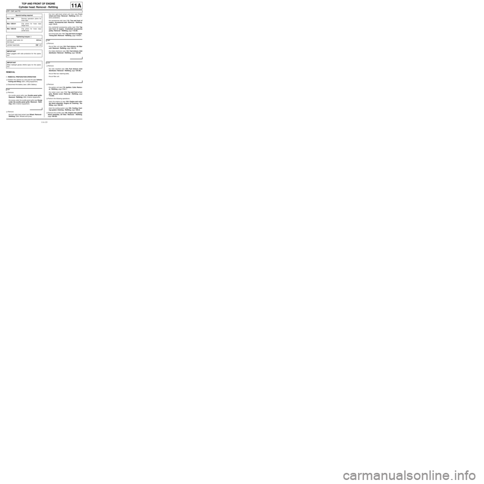
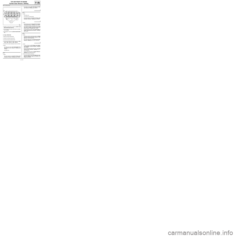
aTighten to torque and in order the cylinder head
bolts (initial torque) (20 N.m).
aCheck that all the cylinder head bolts are pretight-
ened to 20 Nm.
aAngle tighten in order the cylinder head bolts (230˚
±± ± ±
6).
III - FINAL OPERATION
aRefit the exhaust bracket bolts.
aTighten the exhaust bracket bolts.
aConnect the water chamber hoses.
aFit the water chamber hose clips using the tool (Mot.
1448) or (Mot. 1202-01) or (Mot. 1202-02).
aConnect the coolant temperature sensor connector.
aRefit:
-the rocker cover (see 11A, Top and front of en-
gine, Rocker cover: Removal - Refitting, page
11A-66) ,
-the ignition coil.
aRefit:
-the inlet manifold (see 12A, Fuel mixture, Inlet
distributor: Removal - Refitting, page 12A-29) ,-the air filter unit (see 12A, Fuel mixture, Air filter
unit: Removal - Refitting, page 12A-13) .
aRefit:
-the air filter unit,
-the air filter box retaining belts,
-the intake distributor (see 12A, Fuel mixture, Inlet
distributor: Removal - Refitting, page 12A-29) .
aRefit:
-the timing belt (see 11A, Top and front of engine,
Timing belt: Removal - Refitting, page 11A-27) ,
-the crankshaft accessories pulley (see 11A, Top
and front of engine, Crankshaft accessories
pulley: Removal - Refitting, page 11A-20) ,
-the accessories belt (see 11A, Top and front of
engine, Accessories belt: Removal - Refitting,
page 11A-3) .
aRefit:
-the scoop under the scuttle panel grille (see Scoop
under the scuttle panel grille: Removal - Refit-
ting) (56A, Exterior equipment),
-the scuttle panel grille (see Scuttle panel grille:
Removal - Refitting) (56A, Exterior equipment).
aRefit:
-a new oil filter (see 10A, Engine and cylinder
block assembly, Oil filter: Removal - Refitting,
page 10A-29) ,
-the front right-hand wheel arch liner (see Front
wheel arch liner: Removal - Refitting) (55A, Ex-
terior protection),
-the front right-hand wheel (see Wheel: Removal -
Refitting) (35A, Wheels and tyres).
aPerform the following operations:
-top up the engine oil (see 10A, Engine and cylin-
der block assembly, Engine oil: Draining - Re-
filling, page 10A-22) ,
18641
D4F
D7F
D4F
Page 268 of 652
12A-3
FUEL MIXTURE
Air inlet: Description
D7F
12A
120402
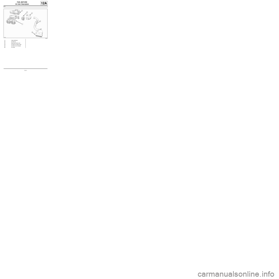
(1) Intake distributor
(2) Air filter box
(3) Motorised throttle valve
(4) Air filter box outlet air pipe
(5) Air filter box air inlet pipe
(6) Air scoop
Page 476 of 652
17B-1
PETROL INJECTION
Petrol injection: List and location of components
D4F, and 772
17B
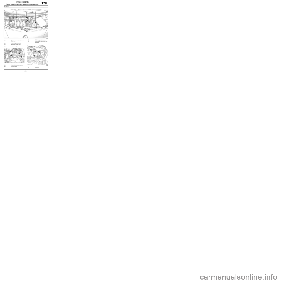
121740
(1) Petrol vapour rebreathing sole-
noid valve
(2) Intake air pressure sensor
(3) Motorised throttle valve
(4) Injection computer
121739
(5) Intake air temperature sensor
(6) Pinking sensor
(7) Coolant temper ature sensor
(8) Engine speed and flywheel posi-
tion sensor
113044
(9) Ignition coil
Page 478 of 652
17B-3
PETROL INJECTION
Petrol injection: List and location of components
D7F, and 800
17B
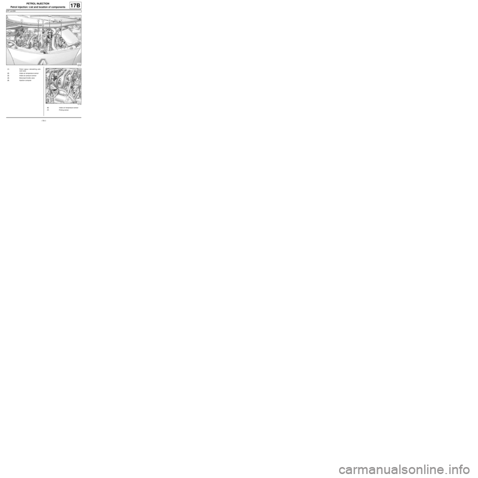
121741
(1) Petrol vapour rebreathing sole-
noid valve
(2) Intake air temperature sensor
(3) Intake air pressure sensor
(4) Motorised throttle valve
(5) Injection computer
121738
(6) Intake air temperature sensor
(7) Pinking sensor
Page 480 of 652
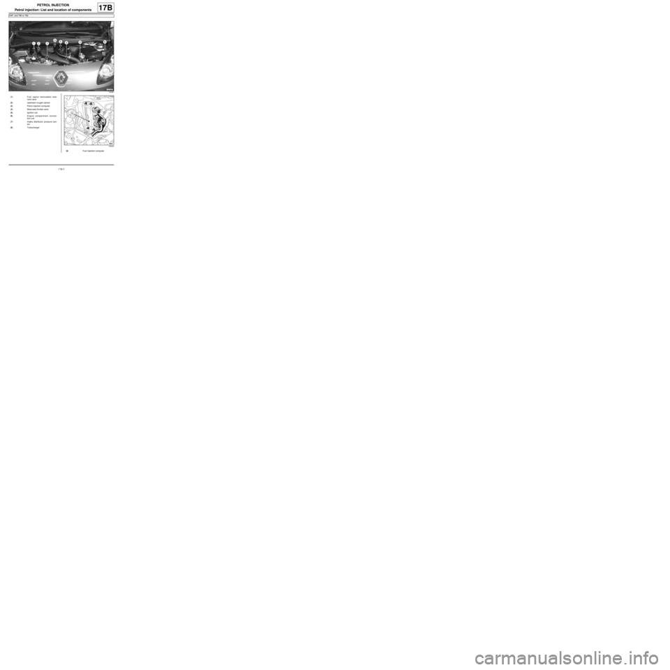
17B-5
PETROL INJECTION
Petrol injection: List and location of components
D4F, and 780 or 782
17B
122387
(1) Fuel vapour recirculation sole-
noid valve
(2) Upstream oxygen sensor
(3) Petrol injection computer
(4) Motorised throttle valve
(5) Ignition coil
(6) Engine compar tment connec-
tion unit
(7) Intake distributor pressure sen-
sor
(8) Turbocharger
108254
(9) Fuel injection computer
Page 502 of 652
17B-27
PETROL INJECTION
Injector rail - Injectors: Removal - Refitting
D4F, and 772
17B
PARTS AND CONSUMABLES FOR THE
REPAIR WORK
aPièces à remplacer systématiquement :
-injector O-ring's,
-injector retaining clips.
REMOVAL
I - REMOVAL PREPARATION OPERATION
aDisconnect the battery (see Battery: Removal - Re-
fitting) ).
aRemove:
-the air filter box (see 12A, Fuel mixture, Air filter
unit: Removal - Refitting, page 12A-13) ,
-the intake distributor (see 12A, Fuel mixture, Inlet
distributor: Removal - Refitting, page 12A-29) .II - OPERATION FOR REMOVAL OF PART
CONCERNED
On the workbench
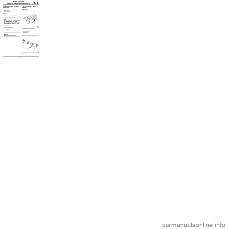
aDisconnect the injector wiring harness.
aRemove:
-the injector rail bolts (1) ,
-the injector rail,
-the injector wiring harness.
aRemove:
-the clips (2) from the injectors, IMPORTANT
During this operation, be sure to:
-refrain from smoking or bringing red hot objects
close to the working area,
-be careful of fuel splashes when disconnecting
the union.
IMPORTANT
Wear latex gloves during the operation.
107885
101492