brake sensor RENAULT TWINGO 2009 2.G Engine And Peripherals Workshop Manual
[x] Cancel search | Manufacturer: RENAULT, Model Year: 2009, Model line: TWINGO, Model: RENAULT TWINGO 2009 2.GPages: 652
Page 84 of 652
10A-78
ENGINE AND CYLINDER BLOCK ASSEMBLY
Engine - gearbox assembly: Removal - Refitting
D4F or D7F
10A
aDrain the coolant circuit (see Refrigerant circuit:
Draining - Filling) .
aRemove:
-the air conditioning pipe bolts on the compressor,
-the air conditioning pipe bolt on the dehydrator res-
ervoir.
aDisconnect the air conditioning pressostat connec-
tor.
a
aDisconnect the fuel supply pipe union.
aInsert the blanking plugs.
aUnclip the fuel pipe on the upper timing cover.aSet the wheels straight ahead.
aPosition the flywheel immobiliser.
aRemove the cover from the universal joint (do not
keep).
aRemove the universal joint bolt (do not keep).
aRemove the universal joint from the steering box.
aDetach the electrical wiring on the cross member.
aLoosen the tie rod lower bolts.
aRemove:
-the tie rod upper bolts.
-the track rod end nuts,
-the track rod ends using the (Tav. 476),
-the lower guide pin bolts,
-the brake pads,
-the calliper mounting bolts,
-the brake callipers, and attach them to the suspen-
sion springs,
-the ABS sensor bolts (if fitted to the vehicle),
-the ABS sensors,
-the shock absorber base lower bolts, AIR CONDITIONING
WARNING
To prevent moisture from entering the system,
place plugs on the cold loop components which
are open to the air.
IMPORTANT
During this operation, be sure to:
-refrain from smoking or bringing red hot objects
close to the working area,
-be careful of fuel splashes when disconnecting
the union.
IMPORTANT
Wear leaktight gloves (Nitrile type) for this opera-
tion.
WARNING
To avoid any corrosion or damage, protect the
areas on which fuel is likely to run.
119544
Page 89 of 652
10A-83
ENGINE AND CYLINDER BLOCK ASSEMBLY
Engine - gearbox assembly: Removal - Refitting
D4F or D7F
10A
aTorque tighten:
-the front subframe bolts (62 N.m),
-the rear subframe bolts (105 N.m),
-the subframe rear tie rod inner bolts (21 N.m),
-the subframe rear tie rod outer bolts (90 N.m),
-the engine tie-bar bolts on the gearbox (105
N.m),
-the engine tie-bar bolt on the subframe (105
N.m).
aRefit the control cables onto the gearbox.
aRemove the blanking plugs from the openings.
aClip the clutch pipe onto the gearbox.
aConnect the clutch slave cylinder.
aRemove the hose clamp (Ms. 583).
aBleed the clutch circuit (see Clutch circuit: Bleed) .
aRefit the gear control linkage.
aAttach the gear control linkage to:
-the gear lever,
-the control lever on the gearbox.
aRefit:
-the heat shield,
-the heat shield bolts.
aRefit the clutch control cable on the manual gearbox.
aRefit the catalytic converter (see 19B, Exhaust,
Catalytic converter: Removal - Refitting, page
19B-12) .aRefit the exhaust downpipe.
aFit the clip.
aTighten the intermediate pipe clip.
aRefit the exhaust downpipe bolts.
aTorque tighten the exhaust downpipe bolts (9
N.m).
aRefit:
-the shock absorber base lower bolts,
-the ABS sensors,
-the ABS sensor bolts (if fitted to the vehicle),
-the brake callipers,
-the calliper mounting bolts,
-the brake pads,
-the lower guide pin bolts,
-track rod ends,
-the track rod end nuts,
-the tie rod upper bolts.
aTorque tighten:
-the shock absorber base lower bolts (105 N.m ),
-the calliper mounting bolts (105 N.m),
-the lower guide pin bolts (34 N.m),
-the track rod end nuts (37 N.m),
-the tie rod upper bolts (21 N.m),
-the tie rod lower bolts (62 N.m).
aClip the electrical wiring on to the cross member.
aFit the steering box universal joint.
aRefit the universal joint bolt.
aTorque tighten the universal joint (24 N.m).
aRemove the flywheel immobiliser.
aClip the fuel pipe on to the upper timing cover.
aConnect the fuel supply pipe union.
aConnect the air conditioning pressostat connector. JH3
JB1 or JH1
D4F, and 772 – D7F
D4F, and 780 or 782
AIR CONDITIONING
Page 107 of 652
10A-101
ENGINE AND CYLINDER BLOCK ASSEMBLY
Engine - gearbox assembly: Removal - Refitting
K4M
10A
aRemove:
-the bolt (27) from the « compressor - intermediate
pipe » connecting pipe,
-the bolt (28) on the « compressor - condenser »
connecting pipe,
-the bolt (29) from the « compressor - intermediate
pipe » connecting pipe mounting.
aDisconnect:
-the pressure sensor connector (30) ,
-the « compressor - intermediate pipe » connecting
pipe,-the « compressor - condenser » connecting pipe.
aInsert the blanking plugs.
aDisconnect the brake servo vacuum pipe union (31)
.
131782
132335
WARNING
To prevent moisture from entering the system,
place plugs on the cold loop components which
are open to the air.
121348
Page 109 of 652
10A-103
ENGINE AND CYLINDER BLOCK ASSEMBLY
Engine - gearbox assembly: Removal - Refitting
K4M
10A
-the rubber pad mounting from the suspended en-
gine mounting on the gearbox.
aRemove the right-hand suspended engine mounting
(see 19D, Engine mounting, Right-hand sus-
pended engine mounting: Removal - Refitting,
page 19D-13) .
aLift the vehicle to remove the "engine and gearbox"
assembly.
REFITTING
I - REFITTING PREPARATION OPERATION
aFor standard engine replacement (see Standard re-
placement) (Technical Note 6023A, 10A, Engine
and peripherals).
II - REFITTING OPERATION
aPosition the "engine and gearbox" assembly in the
body.
aRefit the right-hand suspended engine mounting
(see 19D, Engine mounting, Right-hand sus-
pended engine mounting: Removal - Refitting,
page 19D-13) .
aRefit the rubber pad mounting from the suspended
engine mounting on the gearbox.
aTorque tighten the rubber pad mounting bolts for
the suspended engine mounting on the gearbox
(21 N.m).
aRefit the suspended engine mounting rubber pad.
aTorque tighten:
-the bolts of the suspended mounting rubber
pad (62 N.m),
-the suspended engine mounting shaft nut (62
N.m).
III - FINAL OPERATION
aRemove the.
aRemove the blanking plugs.
aConnect:
-the union of the brake servo vacuum pipe,
-the « compressor - condenser » connecting pipe,-the « compressor - intermediate pipe » connecting
pipe,
-the pressure sensor connector,
aConnect the hose on the coolant pump inlet pipe.
aFit the hose clip on the coolant pump inlet pipe using
the (Mot. 1448).
aRefit the earth nuts.
aClip:
-the relay plates on the engine compartment con-
nection unit,
-the fuse holders.
aConnect the fuses.
aRefit the engine compartment connection unit on the
body.
aConnect the connector to the engine compartment
connection unit.
aRefit the engine compartment connection unit cover.
aClip:
-the wiring on the engine cooling fan assembly,
-the cooling radiator top and bottom hoses on the
engine cooling fan assembly.
aConnect:
-the engine cooling fan assembly resistor connec-
tor,
-the engine cooling fan assembly connector.
aRemove the blanking plug from the fuel supply pipe
opening and the injector rail fuel opening.
aReconnect the fuel supply pipe.
aClip the fuel supply pipe in place.
aConnect:
-the fuel vapour absorber bleed solenoid valve con-
nector,
-the fuel vapour absorber bleed solenoid valve pipe.
aFit the gearbox control cables.
aClip the manual gearbox control cables onto:
-the gear selectors,
-the cable sleeve stops.
aRemove the blanking plug from the hydraulic clutch
control pipe opening and the opening of the clutch
thrust bearing.
aConnect the hydraulic clutch control pipe.
aClip the hydraulic clutch control pipe on the gearbox. Note:
Check no component obstructs the movement of
the body around the engine - gearbox assembly.
Page 232 of 652
11A-115
TOP AND FRONT OF ENGINE
Cylinder head: Removal - Refitting
K9K
11A
aFit blanking plugs to the fuel pipes and the high pres-
sure pump (see 13B, Diesel injection, Diesel in-
jection: Precautions for the repair, page 13B-1) .
aRemove the air filter unit (see 12A, Fuel mixture,
Air filter unit: Removal - Refitting, page 12A-13) .
aUnclip:
-the breather pipe on the gearbox,
-the wiring on the engine lifting eye on the gearbox
side.
aMove aside the engine wiring.
aDisconnect the brake servo pipe from the vacuum
pump.
aRemove the cooling hose clip from the EGR cooler
using the (Mot. 1202-01) or (Mot. 1202-02) or (Mot.
1448).
aDisconnect the cooling hose from the EGR cooler.
aSeparate the clip on the cooling hose of the coolant
pump inlet pipe using the tool (Mot. 1202-01) or
(Mot. 1202-02) or (Mot. 1448).
aDisconnect the cooling hose from the coolant pump
inlet pipe.
aRemove the heater matrix cooling hose clip from the
water chamber using the (Mot. 1202-01) or (Mot.
1202-02) or (Mot. 1448).
aDisconnect:
-the heater matrix cooling hose from the water
chamber,
-the coolant temperature sensor connector.
aRemove the catalytic converter (see 19B, Exhaust,
Catalytic converter: Removal - Refitting, page
19B-12) .aRemove:
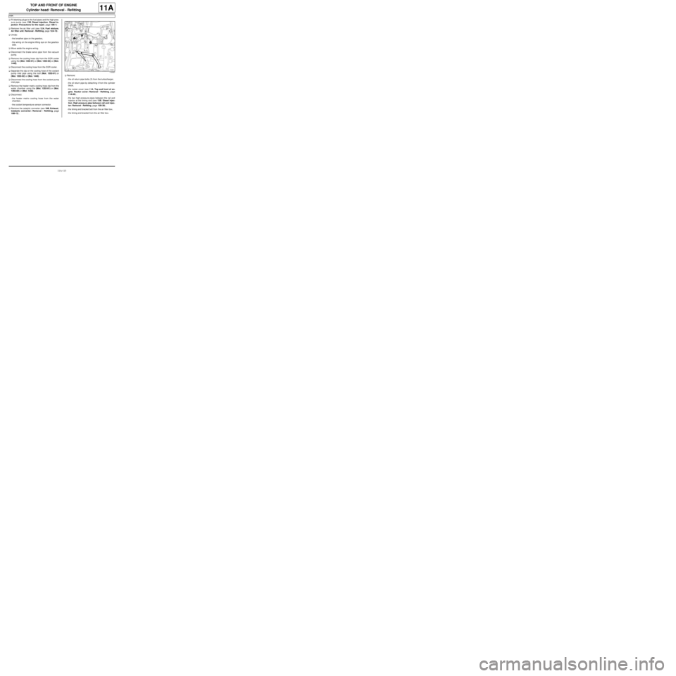
-the oil return pipe bolts (1) from the turbocharger,
-the oil return pipe by detaching it from the cylinder
block,
-the rocker cover (see 11A, Top and front of en-
gine, Rocker cover: Removal - Refitting, page
11A-66) ,
-the two high pressure pipes between the rail and
injector at the timing end (see 13B, Diesel injec-
tion, High pressure pipe between rail and injec-
tor: Removal - Refitting, page 13B-39) ,
-the timing end bracket bolt from the air filter box,
-the timing end bracket from the air filter box.
112327
Page 234 of 652
11A-117
TOP AND FRONT OF ENGINE
Cylinder head: Removal - Refitting
K9K
11A
aIf necessary, carry out a complete check of the cylin-
der head (see Cylinder head: Check) .
II - REFITTING OPERATION FOR PART
CONCERNED
aBring the pistons to mid-stroke position to prevent
them from coming into contact with the valves during
the tightening of the cylinder head.
aRefit:
-a new cylinder head gasket,
-the cylinder head.
Cylinder head tightening procedure
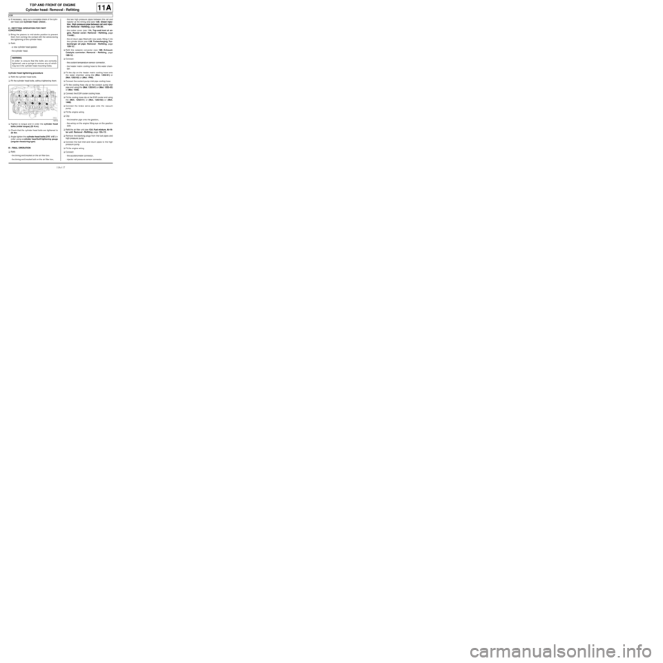
aRefit the cylinder head bolts.
aFit the cylinder head bolts, without tightening them.
aTighten to torque and in order the cylinder head
bolts (initial torque) (25 N.m).
aCheck that the cylinder head bolts are tightened to
25 Nm.
aAngle tighten the cylinder head bolts (270˚ ±± ± ±
10˚) in
order using a cylinder head bolt tightening gauge
(angular measuring type).
III - FINAL OPERATION
aRefit:
-the timing end bracket on the air filter box.
-the timing end bracket bolt on the air filter box,-the two high pressure pipes between the rail and
injector at the timing end (see 13B, Diesel injec-
tion, High pressure pipe between rail and injec-
tor: Removal - Refitting, page 13B-39) ,
-the rocker cover (see 11A, Top and front of en-
gine, Rocker cover: Removal - Refitting, page
11A-66) ,
-the oil return pipe fitted with new seals, fitting it into
the cylinder block (see 12B, Turbocharging, Tur-
bocharger oil pipe: Removal - Refitting, page
12B-12) .
aRefit the catalytic converter (see 19B, Exhaust,
Catalytic converter: Removal - Refitting, page
19B-12) .
aConnect:
-the coolant temperature sensor connector,
-the heater matrix cooling hose to the water cham-
ber.
aFit the clip on the heater matrix cooling hose onto
the water chamber using the (Mot. 1202-01) or
(Mot. 1202-02) or (Mot. 1448).
aConnect the coolant pump inlet pipe cooling hose.
aFit the cooling hose clip at the coolant pump inlet
pipe end using the (Mot. 1202-01) or (Mot. 1202-02)
or (Mot. 1448).
aConnect the EGR cooler cooling hose.
aFit the cooling hose clip at the EGR cooler end using
the (Mot. 1202-01) or (Mot. 1202-02) or (Mot.
1448).
aConnect the brake servo pipe onto the vacuum
pump.
aFit the engine wiring.
aClip:
-the breather pipe onto the gearbox,
-the wiring on the engine lifting eye on the gearbox
side.
aRefit the air filter unit (see 12A, Fuel mixture, Air fil-
ter unit: Removal - Refitting, page 12A-13) .
aRemove the blanking plugs from the fuel pipes and
high pressure pump.
aConnect the fuel inlet and return pipes to the high
pressure pump.
aFit the engine wiring.
aConnect:
-the accelerometer connector,
-injector rail pressure sensor connector, WARNING
In order to ensure that the bolts are correctly
tightened, use a syringe to remove any oil which
may be in the cylinder head mounting holes.
19712
Page 299 of 652
12A-34
FUEL MIXTURE
Inlet distributor: Removal - Refitting
D4F, and 772
12A
aDisconnect:
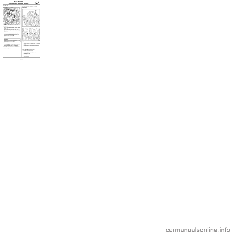
-the oil vapour rebreathing pipe from the inlet dis-
tributor (2) ,
-the non-return valve pipe on the brake servo (3) ,
-the petrol vapour rebreather pipe from the inlet dis-
tributor (4) ,
-the air inlet pressure sensor connector (5) ,
-the inlet air temperature sensor connector (6)
-the throttle valve connector (7) ,
-the injector connectors (8) .
aDisconnect:
-the spark plug high voltage wiring harnesses (9) ,
-the fuel supply pipe union on the injector rail.
aUnpick the engine wiring from the inlet distributor.
aRemove the dipstick.II - OPERATION FOR REMOVAL OF PART
CONCERNED
aRemove:
-the nuts (10) from the inlet distributor on the rocker
cover,
-the inlet distributor bolts from the cylinder head,
-the inlet distributor.
When replacing the inlet distributor
aUsing the workbench, remove:
-the fuel supply pipe to the injector rail,
-the injector rail bolts,
-the throttle valve bolts,
-the throttle valve.
121733
WARNING
To disconnect the spark plug leads, pull on the
extensions and not on the leads.
110421
109729
Page 301 of 652
12A-36
FUEL MIXTURE
Inlet distributor: Removal - Refitting
D4F, and 772
12A
III - FINAL OPERATION
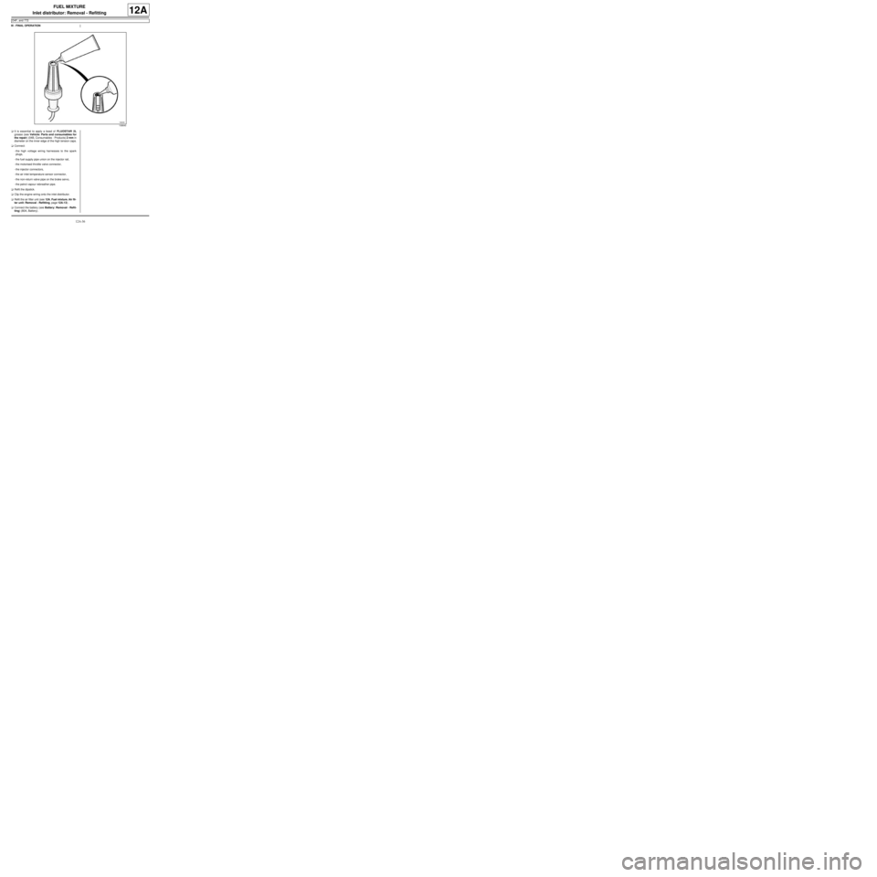
aIt is essential to apply a bead of FLUOSTAR 2L
grease (see Vehicle: Parts and consumables for
the repair) (04B, Consumables - Products) 2 mm in
diameter on the inner edge of the high tension caps.
aConnect:
-the high voltage wiring harnesses to the spark
plugs,
-the fuel supply pipe union on the injector rail,
-the motorised throttle valve connector,
-the injector connectors,
-the air inlet temperature sensor connector,
-the non-return valve pipe on the brake servo,
-the petrol vapour rebreather pipe.
aRefit the dipstick.
aClip the engine wiring onto the inlet distributor.
aRefit the air filter unit (see 12A, Fuel mixture, Air fil-
ter unit: Removal - Refitting, page 12A-13) .
aConnect the battery (see Battery: Removal - Refit-
ting) (80A, Battery).
106640
Page 306 of 652
12A-41
FUEL MIXTURE
Inlet distributor: Removal - Refitting
K4M
12A
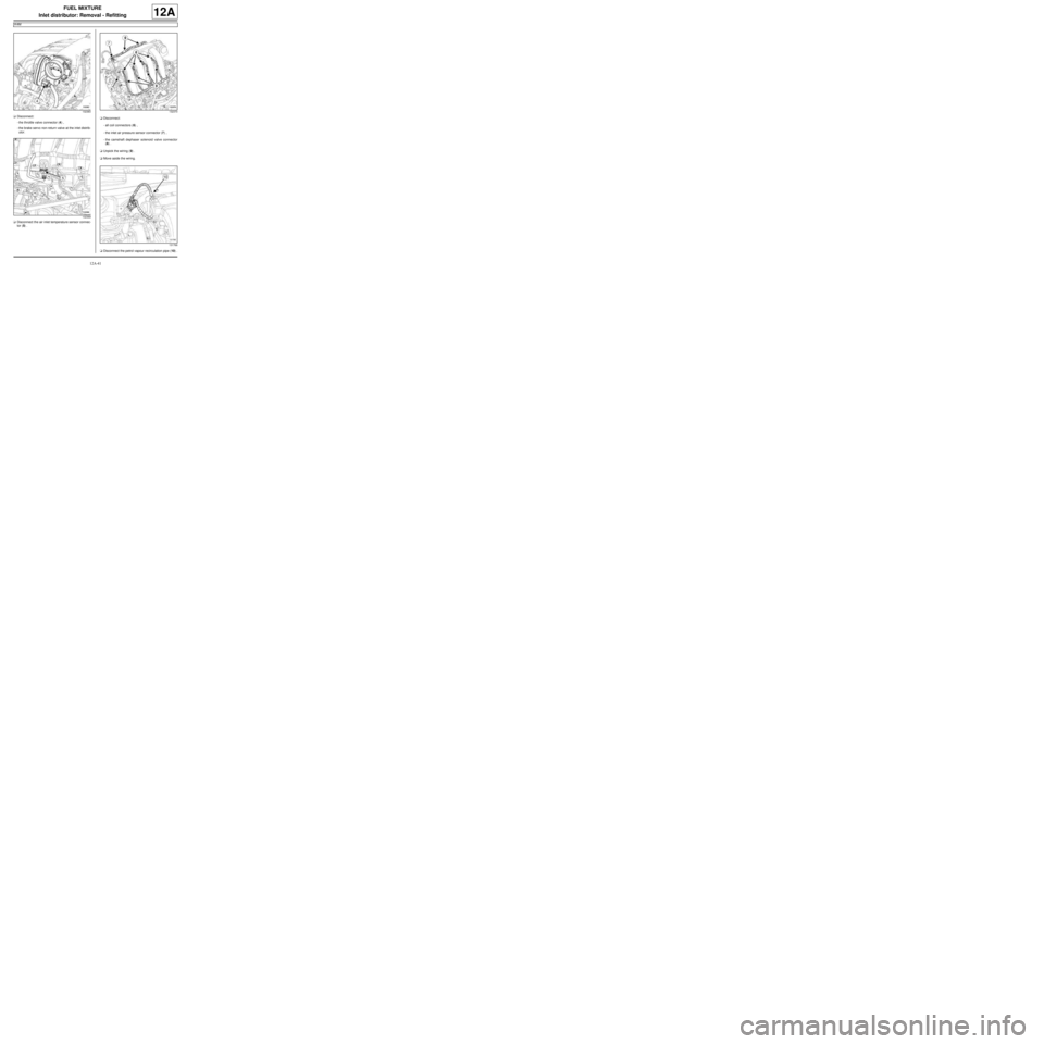
aDisconnect:
-the throttle valve connector (4) ,
-the brake servo non-return valve at the inlet distrib-
utor.
aDisconnect the air inlet temperature sensor connec-
tor (5) .aDisconnect:
-all coil connectors (6) ,
-the inlet air pressure sensor connector (7) ,
-the camshaft dephaser solenoid valve connector
(8) .
aUnpick the wiring (9) .
aMove aside the wiring.
aDisconnect the petrol vapour recirculation pipe (10) .
132383
132369132370
131766
Page 308 of 652
12A-43
FUEL MIXTURE
Inlet distributor: Removal - Refitting
K4M
12A
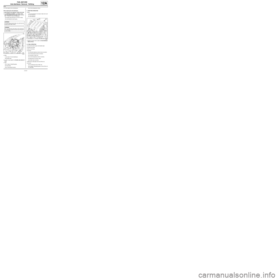
aFit new seals to the inlet distributor.
When replacing the inlet distributor
aparts always to be replaced: Throttle valve seal.
aUse SURFACE CLEANER (see Vehicle: Parts
and consumables for the repair) (04B, Consuma-
bles - Products) to clean and degrease:
-the throttle valve joint face if it is to be re-used,
-the inlet distributor seal housing.
aRefit:
-a new seal on the inlet distributor,
-the throttle valve.
aIn order, torque tighten the throttle valve bolts (10
N.m).
aRefit:
-the oil vapour rebreathing pipe,
-the heat shield,
-the air inlet pressure sensor,-the air inlet temperature sensor.
II - REFITTING OPERATION
aRefit:
-a new seal between the injector holder shim and
the inlet distributor,
-the inlet distributor.
aTighten to torque and in order the inlet distributor
bolts (12 N.m).
III - FINAL OPERATION
aConnect the petrol vapour recirculation pipe.
aPosition the wiring.
aClip on the wiring.
aConnect:
-the camshaft dephaser solenoid valve connector,
-the air inlet pressure sensor connector,
-the connector of each coil,
-the air inlet temperature sensor connector,
-the brake servo non-return valve,
-the throttle valve connector.
aRefit the air outlet pipe onto the air filter unit.
aConnect:
-the air outlet pipe of the air filter unit,
-the oil vapour rebreathing pipe on the air filter unit
air outlet pipe. WARNING
The joint faces must be clean, dr y and free from
grease (avoid finger marks).
WARNING
Do not scrape the joint faces of the aluminium,
any damage caused to the joint face will result in
a risk of leaks.
132383
132371