check engine RENAULT TWINGO 2009 2.G Engine Diesel Injection Workshop Manual
[x] Cancel search | Manufacturer: RENAULT, Model Year: 2009, Model line: TWINGO, Model: RENAULT TWINGO 2009 2.GPages: 269
Page 1 of 269
1Engine and peripherals
V6 MR-413-X44-13B000$TOC.mif
V6
13B
"The repair procedures given by the manufacturer in this document are based on the
technical specifications current when it was prepared.
The procedures may be modified as a result of changes introduced by the
manufacturer in the production of the various component units and accessories from
which his vehicles are constructed."
V6
All rights reserved by Renault s.a.s.
Edition Anglaise
Copying or translating, in part or in full, of this document or use of the service part
reference numbering system is forbidden without the prior written authority of
Renault s.a.s.
© Renault s.a.s. 2009
DIESEL INJECTION
DCM 1.2 Injection
Program No.: 4D
Vdiag No.: 48, 4C, 50, 54, 58, 5C
Fault finding – Introduction 13B - 2
Fault finding – Cleanliness guidelines 13B - 8
Fault finding – List and location of components 13B - 10
Fault finding – Function 13B - 12
Fault finding – Role of components 13B - 21
Fault finding – Replacement of components 13B - 23
Fault finding – Configuration and programming 13B - 26
Fault finding – Fault summary table 13B - 27
Fault finding – Interpretation of faults 13B - 29
Fault finding – Conformity check 13B - 125
Fault finding – Status summary table 13B - 126
Fault finding – Interpretation of statuses 13B - 127
Fault finding – Parameter summary table 13B - 169
Fault finding – Interpretation of parameters 13B - 171
Fault finding – Command summary table 13B - 205
Fault finding – Tests 13B - 207
Fault finding – Customer complaints 13B - 235
Fault finding – Fault finding charts 13B - 236
Page 8 of 269
13B-8V6 MR-413-X44-13B000$020.mif
13B
DCM 1.2 Injection
Program No.: 4D
Vdiag No.: 48, 4C, 50,
54, 58, 5C
I. HAZARDS ASSOCIATED WITH CONTAMINATION
The high pressure direct injection system is highly sensitive to contamination. The risks associated with
contamination are:
–damage to or destruction of the high pressure injection system,
–components jamming,
–components losing seal integrity.
All After-Sales operations must be performed under very clean conditions. This means that no impurities
(particles a few microns in size) should have entered the system during dismantling.
The cleanliness principle must be applied from the filter to the injectors.
What are the sources of contamination?
–metal or plastic swarf,
–paint,
–fibres: from cardboard,
from brushes,
from paper,
from clothing,
from cloths.
–foreign bodies such as hair,
–ambient air
–etc.
II. ADVICE TO BE FOLLOWED BEFORE ANY OPERATION
Check that you have plugs for the unions to be opened (set of plugs available from the Parts Department). The plugs
are single-use only. After use, they must be discarded (once used they are soiled and cleaning is not sufficient to
make them reusable). Unused plugs must also be discarded.
Check that you have hermetically resealable plastic bags for storing removed parts. Parts stored in this way will be
less susceptible to the risk of contamination. The bags are single-use only. Once used, they must be thrown out.
Use lint-free cleaning cloths (cloth part reference 77 11 211 707). Using normal cloth or paper is prohibited. They are
not lint-free and could contaminate the fuel circuit. Each cloth should only be used once.
Use fresh cleaning agent for each operation (used cleaning agent is contaminated). Pour it into an uncontaminated
container.
For each operation, use a clean brush in good condition (the brush must not shed its bristles).
Use a brush and cleaning agent to clean the unions to be opened.IMPORTANT
Cleaning the engine using a high pressure washer is prohibited because of the risk of damaging connections. In
addition, moisture may collect in the connectors and create electrical connection faults.
IMPORTANT
Before any work is carried out on the high pressure injection system, protect:
–the accessories and timing belts,
–the electrical accessories, (starter, alternator, electric power-assisted steering pump),
–the flywheel surface, to prevent any diesel from running onto the clutch friction plate.
DIESEL INJECTION
Fault finding – Cleanliness guidelines
Page 12 of 269
13B-12V6 MR-413-X44-13B000$040.mif
13B
DCM 1.2 Injection
Program No.: 4D
Vdiag No.: 48, 4C, 50,
54, 58, 5C
System outline
The DCM1.2 injection system used on the K9K engine is an electronically-managed high pressure injection system.
The fuel is compressed by a high pressure pump then stored in a rail that feeds the injectors. Injection takes place
when a current pulse is applied to the injector holders. The amount injected is proportional to the rail pressure
and the applied pulse length, and the start of injection is synchronised with the start of the pulse.
The system includes two subsystems, which have different fuel pressure levels:
–The low pressure circuit contains the tank, the diesel fuel filter, the transfer pump and the injector holder
return pipes,
–the high-pressure system includes the high-pressure pump, rail, injector holders and high-pressure pipes.
Finally, there are a certain number of sensors and regulating actuators for controlling and monitoring the entire
system.
Functions performed:
Function: Fuel supply management (timing, flow and pressure).
Quantity of fuel injected and injection timing setting
The injection checking parameters are the quantities to be injected and their respective timing.
These are calculated by the computer using signals from the following sensors:
–engine speed sensor (Crankshaft + Cam lobe for synchronisation),
–accelerator pedal sensor,
–coolant temperature sensor,
–rail pressure sensor,
–atmospheric pressure sensor,
–accelerometer,
–inlet manifold pressure sensor.
Specific vehicle / engine suffix details:
Modus
K9K 750 752 (Euro 3)Inlet manifold temperature and pressure sensor (a sensor which has two functions),
management by the turbocharger control solenoid valve inlet pressure.
K9K 766 (Euro 4)Either a flow sensor with an integrated temperature sensor or a temperature sensor
instead of a flow sensor with inlet manifold temperature sensor, inlet manifold pressure
sensor, management by turbocharger control solenoid valve programming.
K9K 768 (Euro 4)Flow sensor with integrated temperature sensor, inlet manifold pressure sensor,
management by the turbocharger control solenoid valve inlet pressure.
DIESEL INJECTION
Fault finding – Function
Page 13 of 269
13B-13V6 MR-413-X44-13B000$040.mif
DIESEL INJECTION
Fault finding – Function13B
DCM 1.2 Injection
Program No.: 4D
Vdiag No.: 48, 4C, 50,
54, 58, 5C
The quantities to be injected and their respective timing are converted into:
–a reference tooth,
–the time between this tooth and the start of the pulse,
–the time during which the supply to the injector holder is on.
An electrical current (pulse) is sent to each injector holder according to previously calculated data. The system
carries out one to four injections (one pilot injection, one pre-injection, one main injection, one post-injection).
The general principle is to calculate the total injection flow which is then divided between the injection stages to
promote correct combustion and reduce pollutant emissions.
An accelerometer checks some of the fuel injection deviation. This has several functions:
–Protecting the engine by detection of injection system leaks.
–Checking the quantity injected by measuring deviations and variations.
By changing both the injection duration and advance, the system readjusts the quantity of fuel injected
and the mixture's moment of ignition.Clio III
K9K 750 752 (Euro 3)Inlet manifold temperature and pressure sensor (a sensor which has two functions),
management by the turbocharger control solenoid valve inlet pressure.
K9K 766 (Euro 4)Either a flow sensor with an integrated temperature sensor or a temperature sensor
instead of a flow sensor with inlet manifold temperature sensor, inlet manifold pressure
sensor, management by turbocharger control solenoid valve programming.
K9K 768 (Euro 4)Flow sensor with integrated temperature sensor, inlet manifold pressure sensor,
management by the turbocharger control solenoid valve inlet pressure.
Megane II / Scenic II
K9K 724 (Euro 4)Either a flow sensor with an integrated temperature sensor or a temperature sensor
instead of a flow sensor with inlet manifold temperature sensor, inlet manifold pressure
sensor, management by turbocharger control solenoid valve programming.
New Twingo No UPC (Protection and Switching Unit).
K9K 740 (Euro 4)Temperature sensor instead of the flow sensor with inlet manifold pressure
and temperature sensor, management by the turbocharger control solenoid valve inlet
pressure, water in diesel fuel sensor depending on target export countries.
Kangoo 2
K9K 800 802 (Euro 4)The flow of fresh air entering the engine is given by a hot wire ratiometric sensor. This
flow sensor facilitates control of the amount of exhaust gas sent for recirculation, thus
ensuring the best possible recirculation rates. An air temperature sensor is integrated
into the flow sensor.
Air flow measurement facilitates closed-loop control via the EGR valve.
K9K 812 (Euro 3)Temperature sensor instead of the flow sensor with inlet manifold pressure
and temperature sensor, management by the turbocharger control solenoid valve inlet
pressure.
Page 14 of 269
13B-14V6 MR-413-X44-13B000$040.mif
DIESEL INJECTION
Fault finding – Function13B
DCM 1.2 Injection
Program No.: 4D
Vdiag No.: 48, 4C, 50,
54, 58, 5C
Rail pressure check
The quality of combustion is influenced by the size of the atomised droplets in the cylinder.
In the combustion chamber, smaller fuel droplets will have time to burn fully, and will not produce smoke or unburned
particles. To meet emission control requirements, the droplet size must be reduced and therefore the injection holes
must be smaller.
With smaller holes, less fuel will be able to be introduced at a given pressure, which limits the power. To offset this
disadvantage, the quantity of fuel injected must be increased, which means increased pressure (and more holes in
the injector nozzles). In the Delphi Common Rail injection system, the pressure in the rail can reach 1600 bar
and must be constantly controlled. The measuring circuit comprises an active pressure sensor on the rail connected
to an analogue port on the computer.
The High Pressure pump is supplied at low pressure (5 bar) by a built-in transfer pump. This pump supplies the rail.
The rail filling pressure is controlled by the filling valve (IMV) and the discharge pressure is controlled by the injector
valves. This compensates for pressure drops. The filling actuator enables the high pressure pump to supply
the exact quantity of diesel fuel required to maintain the rail pressure. This mechanism minimises the heat generated
and improves engine output.
In order to discharge the rail using the injector valves, the valves are actuated by short electrical pulses which are:
–short enough not to open the injector (fuel passes through the return circuit from the injectors),
–long enough to open the valves and discharge the rail.
The fuel surplus is sent back to the fuel filter or the tank, according to its flow. If there is no IMV* control, the rail
pressure is limited by a discharge valve on the pump.
IMV*: Filling actuator.
Idling speed regulation
The computer handles the calculation of idling speed. This has to take account of the instantaneous power level to
be supplied, according to the following factors:
–engine coolant temperature,
–gear ratio engaged,
–battery charge,
–electrical consumers (Additional heating, Air conditioning, Fan assembly, heated windscreen, etc.) active
or inactive,
–system faults detected.
Individual injector correction (C2I)
The DCM1.2 system injectors must be calibrated with corrective values so that their flow may be adjusted precisely.
Each injector is calibrated for different pressures on a test bench, and its specifications are shown on a label
attached to the body of the injector holders. These individual correction values are then entered into the computer
memory, which can control the injectors, taking their manufacturing variations into account.
Page 19 of 269
13B-19V6 MR-413-X44-13B000$040.mif
DIESEL INJECTION
Fault finding – Function13B
DCM 1.2 Injection
Program No.: 4D
Vdiag No.: 48, 4C, 50,
54, 58, 5C
Instrument panel display
The computer manages the data display on the instrument panel relating to engine operation. This covers five
functions: the OBD warning light for European On Board Diagnostics (EOBD), pre-postheating, coolant temperature,
and Level 1 (non critical fault) and Level 2 (emergency stop) engine faults. These five functions are represented by
five warning lights or messages displayed by the trip computer.
Pre-postheating warning light
This warning light indicates that preheating is active.
Engine coolant temperature warning light
This warning light is used as an engine overheating indicator.
–In the event of overheating, it is up to the driver whether to stop the vehicle or continue driving.
OBD warning light
The OBD fault warning light is used to warn the driver of the presence of injection faults producing excessive
pollution or that the EOBD system is deactivated.
The injection computer requests illumination of the OBD warning light for a present fault only after three consecutive
driving cycles.
The visual check of the warning light when the power is switched on (automatic test procedure managed by
the instrument panel) is carried out by the injection computer. It lasts 3 seconds or until the engine starts for
the New Twingo and Kangoo 2.
If a confirmed OBD fault causes the OBD warning light to come on, there should be no flashing after the warning
light illumination test. The instrument panel will also display the message: Check emission control.
The gearbox computer, if fitted, may also request the illumination of this warning light.
Level 1 warning
If there is a minor fault, the computer may request a level 1 warning to be displayed. Usually, the instrument panel
switches on the SERVICE warning light and sends out a "Check the injection" message. Refer to the operation of the
instrument panel (see 83A, instrument panel). Note:
This warning light comes on only if the vehicle is EOBD approved.
Note:
The SERVICE warning light will come on if the instrument panel is configured as cruise control - speed
limiter present, but the function has not yet been detected by the injection computer.
Page 24 of 269
13B-24V6 MR-413-X44-13B000$060.mif
DIESEL INJECTION
Fault finding – Replacement of components13B
DCM 1.2 Injection
Program No.: 4D
Vdiag No.: 48, 4C, 50,
54, 58, 5C
Note:
If commands SC001 Enter saved data and SC003 Save computer data have been lost or if they are not operating
after programming the computer:
–Save the C2I of each injector manually by reading the C2I on each injector and use command SC002 Enter
injector codes (see injector replacement).
–Use command AC028 Static test to reinitialise the computer (fan assembly, etc.).
–Switch the ignition off and then on again.
Clear the engine management computer faults.
For Clio III, Modus, and New Twingo only:
After programming a new injection computer:
–Switch the ignition off and then on again.
–Select the UCH domain using the diagnostic tool.
–In repair mode, run command SC017 Injection immobiliser code programming, and follow
the instructions given by the diagnostic tool.
–Switch the ignition off and then on again.
–Select the INJECTION subgroup and check that status ET006 is Code programmed.
If ET006 Code programmed = YES, go on to the next steps; if ET006 = NO, run command SC017 Injection
immobiliser code programming again, and follow the instructions given by the diagnostic tool.
Note:
If commands SC001 Enter saved data and SC003 Save computer data have been lost or if they are not operating
after programming the computer:
–Save the C2I of each injector manually by reading the C2I on each injector and use command SC002 Enter
injector codes (see injector replacement).
–Use command AC028 Static test to reinitialise the computer (fan assembly, etc.).
–Switch the ignition off and then on again.
–Clear the engine management computer faults.
IMPORTANT
It is not possible to try an injection computer from the Parts Department as it will not be possible to fit it on another
vehicle afterwards.
Page 29 of 269
13B-29
AFTER REPAIRDeal with any faults displayed by the diagnostic tool.
Clear the computer fault memory.
Carry out a road test followed by another check with the diagnostic tool.
V6 MR-413-X44-13B000$090.mif
13B
DCM 1.2 Injection
Program No.: 4D
Vdiag No.: 48, 4C, 50,
54, 58, 5C
DF001
PRESENT
OR STOREDCOOLANT TEMPERATURE SENSOR CIRCUITCO.1: Open circuit or short circuit to +12 V
CC.0: Short circuit to earth
NOTESSpecial notes:
If fault DF001 is present, the preheating time is greater than 10 seconds and the engine
fan switches on at low speed (Fan assembly 1). If there is a fault on Fan assembly 1,
then on vehicles fitted with air conditioning, Fan assembly 2 switches on.
See the Technical Note Wiring Diagrams for the vehicle.
Check the connection and condition of the coolant temperature sensor connector, component code 244.
Check the connection and condition of connector B (brown 48-track) of the injection computer, component
code 120.
If the connector(s) is faulty and if there is a repair procedure (see Technical Note 6015A, Repairing electrical
wiring, Wiring: Precautions for repair), repair the connector, otherwise replace the wiring.
Measure the resistance of component 244 between connections 3JK and 3C.
If the resistance of the coolant temperature sensor is not:
at –40
°C: 68780 ΩΩ Ω Ω
< X < 82780 ΩΩ Ω Ω
at –10
°C: 11332 ΩΩ Ω Ω
< X < 13588 ΩΩ Ω Ω
at 25
°C: 2140 ΩΩ Ω Ω
< X < 2364 ΩΩ Ω Ω
at 50
°C: 772 ΩΩ Ω Ω
< X < 850 ΩΩ Ω Ω
at 80
°C: 275 ΩΩ Ω Ω
< X < 291 ΩΩ Ω Ω
at 110
°C: 112 ΩΩ Ω Ω
< X < 118 ΩΩ Ω Ω
at 120
°C: 86 ΩΩ Ω Ω
< X < 90 ΩΩ Ω Ω
,
replace the coolant temperature sensor, component code 244 (see MR 364 (Mégane II), MR 370 (Scénic II),
MR 385 (Modus), MR 392 (Clio III), MR 411 (New Twingo), MR 417 (Kangoo 2) Mechanical, 19A, Cooling,
Coolant temperature sensor: Removal - Refitting).
Check the insulation and continuity of the following connections:
–3JK between components 120 and 244,
–3C between components 120 and 244.
If the connection or connections are faulty and there is a repair procedure (see Technical Note 6015A, Electrical
wiring repair, Wiring: Precautions for repair), repair the wiring, otherwise replace the wiring.
If the fault is still present, replace the coolant temperature sensor, component code 244 (see MR 364 (Mégane II),
MR 370 (Scénic II), MR 385 (Modus), MR 392 (Clio III), MR 411 (New Twingo), MR 417 (Kangoo 2) Mechanical,
19A, Cooling, Coolant temperature sensor: Removal - Refitting).
If the fault is still present, contact the Techline.
DCM1.2_V48_DF001/DCM1.2_V4C_DF001/DCM1.2_V50_DF001/DCM1.2_V54_DF001/DCM1.2_V58_DF001/DCM1.2_V5C_DF001
DIESEL INJECTION
Fault finding – Interpretation of faults
Page 30 of 269
13B-30
AFTER REPAIRDeal with any faults displayed by the diagnostic tool.
Clear the computer fault memory.
Carry out a road test followed by another check with the diagnostic tool.
V6 MR-413-X44-13B000$090.mif
DIESEL INJECTION
Fault finding – Interpretation of faults13B
DCM 1.2 Injection
Program No.: 4D
Vdiag No.: 48, 4C, 50,
54, 58, 5C
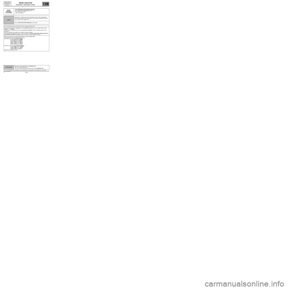
DF002
PRESENT
OR STOREDAIR TEMPERATURE SENSOR CIRCUITCO.1: Open circuit or short circuit to +12 V
CC.0: Short circuit to earth
1.DEF: inconsistency
NOTESDepending on the engine type, the air temperature is given by the air temperature
sensor, which is either on the air flowmeter or in place of the air flowmeter on K9K 724,
740, 766, 768, and 812 engines only.
See the Technical Note Wiring Diagrams for the vehicle.
The air temperature sensor in the flow sensor has a separate electrical circuit.
Move the wiring between the computer and the air temperature sensor to see if a change of status occurs
(present stored).
Look for any wiring damage and check the connection and condition of the air temperature sensor and its
connections.
Check the connection and condition of the injection computer connector.
If the connector(s) is faulty and if there is a repair procedure (see Technical Note 6015A, Repairing electrical
wiring, Wiring: Precautions for repair), repair the connector, otherwise replace the wiring.
Measure the resistance of component 272 between connections 3JQ and 3B.
If the resistance of the air temperature sensor is not:
(theoretical values for engines with flowmeter)
at -10
°C: 8716 ΩΩ Ω Ω
< X < 9688 ΩΩ Ω Ω
at 0
°C: 5497 ΩΩ Ω Ω
< X < 6051 ΩΩ Ω Ω
at 10
°C: 3553 ΩΩ Ω Ω
< X < 3875 ΩΩ Ω Ω
at 20
°C: 2353 ΩΩ Ω Ω
< X < 2543 ΩΩ Ω Ω
at 30
°C: 1613 ΩΩ Ω Ω
< X < 1729 ΩΩ Ω Ω
(theoretical values for engines without flowmeter)
at -10
°C: 8623 ΩΩ Ω Ω
< X < 10454 ΩΩ Ω Ω
at 25
°C: 1928 ΩΩ Ω Ω
< X < 2174 ΩΩ Ω Ω
at 50
°C: 763 ΩΩ Ω Ω
< X < 857 ΩΩ Ω Ω
,
replace the air temperature sensor.
DCM1.2_V48_DF002/DCM1.2_V4C_DF002/DCM1.2_V50_DF002/DCM1.2_V54_DF002/DCM1.2_V58_DF002/DCM1.2_V5C_DF002
Page 33 of 269
13B-33
AFTER REPAIRDeal with any faults displayed by the diagnostic tool.
Clear the computer fault memory.
Carry out a road test followed by another check with the diagnostic tool.
V6 MR-413-X44-13B000$090.mif
DIESEL INJECTION
Fault finding – Interpretation of faults13B
DCM 1.2 Injection
Program No.: 4D
Vdiag No.: 48, 4C, 50,
54, 58, 5C
DF003
CONTINUED
Check the insulation and continuity of the following connections:
On K9K 740 engines only:
–AP29 between components 120 and 1016,
–NH between component 120 and earth,
–3FB between components 120 and 238.
For the other engine suffixes:
–AP15 between components 120 and 1337,
–NH or N between component 120 and earth,
–3FB between components 120 and 1337,
–3FB1 between components 120 and 1337,
–3FB2 between components 120 and 1337.
If the connection or connections are faulty and there is a repair procedure (see Technical Note 6015A, Electrical
wiring repair, Wiring: Precautions for repair), repair the wiring, otherwise replace the wiring.
If the fault is still present, contact the Techline.