key RENAULT TWINGO 2009 2.G Heating And Air Conditioning - Climate Control Workshop Manual
[x] Cancel search | Manufacturer: RENAULT, Model Year: 2009, Model line: TWINGO, Model: RENAULT TWINGO 2009 2.GPages: 99
Page 2 of 99
62B-2
MR-413-X44-62B000$046_eng.mif
V1
62B
CLIMATE CONTROL
Fault finding - Introduction
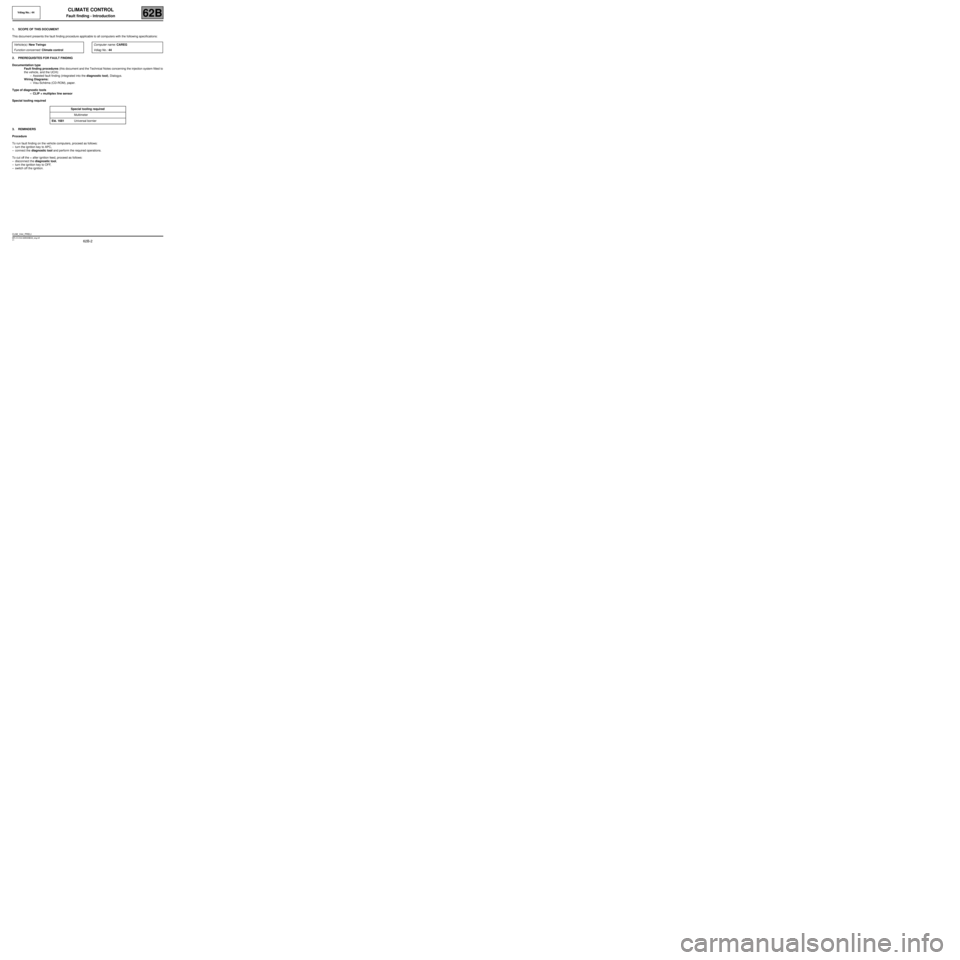
1. SCOPE OF THIS DOCUMENT
This document presents the fault finding procedure applicable to all computers with the following specifications:
2. PREREQUISITES FOR FAULT FINDING
Documentation type
Fault finding procedures (this document and the Technical Notes concerning the injection system fitted to
the vehicle, and the UCH):
–Assisted fault finding (integrated into the diagnostic tool), Dialogys.
Wiring Diagrams:
–Visu-Schéma (CD-ROM), paper.
Type of diagnostic tools
–CLIP + multiplex line sensor
Special tooling required
3. REMINDERS
Procedure
To run fault finding on the vehicle computers, proceed as follows:
–turn the ignition key to APC,
–connect the diagnostic tool and perform the required operations.
To cut off the + after ignition feed, proceed as follows:
–disconnect the diagnostic tool,
–turn the ignition key to OFF,
–switch off the ignition. Vehicle(s): New Twingo
Function concerned: Climate controlComputer name: CAREG
Vdiag No.: 44
Special tooling required
Multimeter
Elé. 1681 Universal bornier
CLIM_V44_PRELI
Vdiag No.: 44
MR-413-X44-62B000$046_eng.mif
Page 18 of 99
62B-18
MR-413-X44-62B000$230_eng.mif
V1
Vdiag No.: 44CLIMATE CONTROL
Fault finding - Function62B
Vehicle
multiplex
network
Internal
temperature
sensor
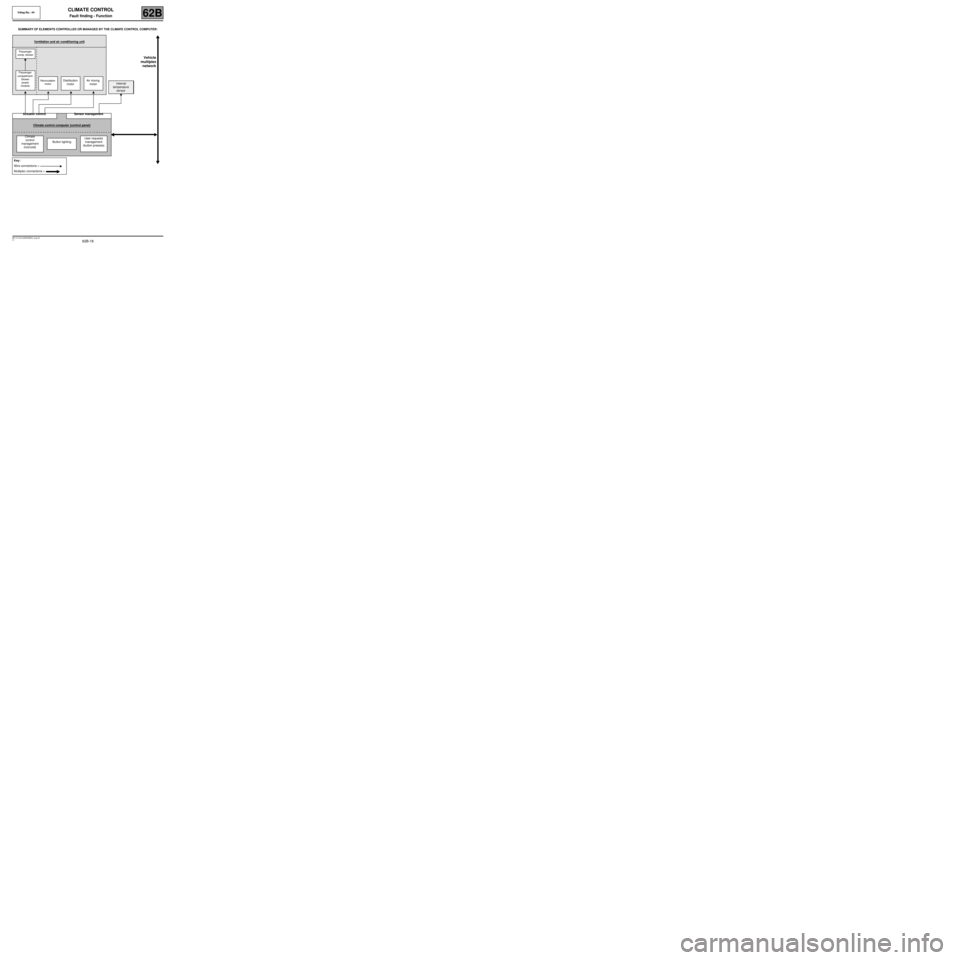
SUMMARY OF ELEMENTS CONTROLLED OR MANAGED BY THE CLIMATE CONTROL COMPUTER:
Ventilation and air conditioning unit
Passenger
comp. blower
Passenger
compartment
blower
power
module
Recirculation
motorDistribution
motorAir mixing
motor
Actuator control Sensor management
Climate control computer (control panel)
Climate
control
management
(hot/cold)Button lightingUser requests
management
(button presses)
Key:
Wire connections =
Multiplex connections =
Page 19 of 99
62B-19
MR-413-X44-62B000$230_eng.mif
V1
Vdiag No.: 44CLIMATE CONTROL
Fault finding - Function62B
Vehicle
multiplex
network
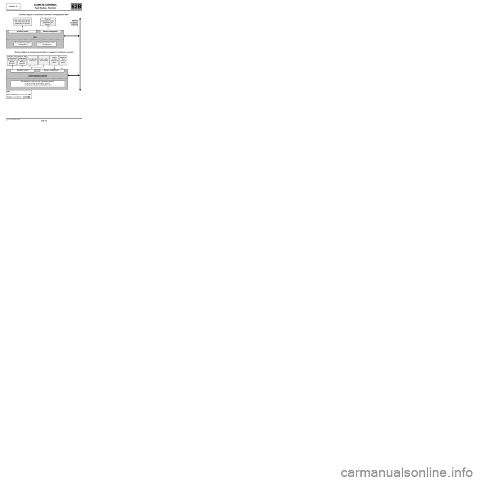
Summary diagram of components controlled or managed by the UCH:
Summary diagram of components controlled or managed by the injection computer Rear screen de-icing and
rear-view mirror de-icer
(depending on version)External
temperature sensor
(depending on
version)
Actuator control Sensor management
UCH
Air conditioning request
managementHeated rear screen control
management
Relay No. 1 for
the Passenger
Compartment
Heating
ResistorsRelay No. 2 for
the Passenger
Compartment
Heating
ResistorsAir conditioning
compressorEngine cooling
fan assemblyEngine
coolant
temperature
sensorRefrigerant
fluid
pressure
sensor
Actuator control Sensor management
Engine injection computer
Management of the cold loop (refrigerant pressure,
engine cooling fan activation request,
compressor activation authorisation, etc.)
Key:
Wire connections =
Multiplex connections =
Page 20 of 99
62B-20
MR-413-X44-62B000$230_eng.mif
V1
Vdiag No.: 44CLIMATE CONTROL
Fault finding - Function62B
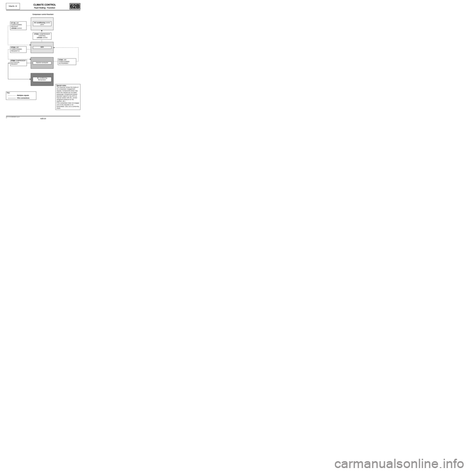
ET004: AIR
CONDITIONING
AUTHORISED
Special notes:
This flowchart shows the tracks of
the compressor engagement
request. Components which may
block this request are not listed
(passenger compartment blower
operation signal for the UCH on
manual version with AC, correct
refrigerant pressure for the
injection, etc.).
If the compressor does not engage
(one of the requests is not
transmitted): carry out a conformity
check.
Compressor control flowchart:
ET140: AIR
CONDITIONING
REQUEST
(climate control)Air conditioning control
panel
ET020: COMPRESSOR
CONTROL
(climate control)
ET030: AIR
CONDITIONING
REQUEST 2UCH
ET088: COMPRESSOR
ACTIVATION
REQUEST
Injection computer
Air conditioning
Compressor
Key:
: Multiplex signals
: Wire connections
Page 68 of 99
62B-68
MR-413-X44-62B000$828_eng.mif
V1
62B
CLIMATE CONTROL
Diagnostic - Fault finding chart
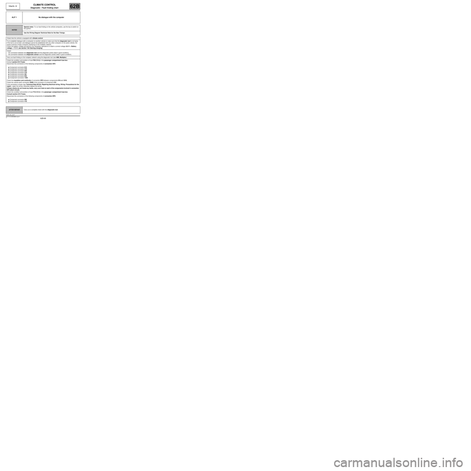
ALP 1 No dialogue with the computer
NOTESSpecial notes: To run fault finding on the vehicle computers, use the key to switch on
the ignition.
Use the W iring Diagram Technical Note for the New Twingo.
Check that the vehicle is equipped with climate control.
Try to establish dialogue with a computer on another vehicle to make sure that the diagnostic tool is not faulty.
If the tool is not at fault, and dialogue cannot be established with any other computer on the same vehicle, the
cause could be a faulty computer interfering on the multiplex network.
Check the battery voltage and perform the necessary operations to obtain a correct voltage (9.5 V < Battery
voltage < 17.5 V, see section 16A Starting-charging).
Check:
–the connection between the diagnostic tool and the diagnostic probe (lead in good condition),
–the connection between the diagnostic sensor and the diagnostic socket (lead in good condition).
Carry out fault finding on the multiplex network using the diagnostic tool (see 88B, Multiplex).
Check the condition and position of fuse F29 (15 A) in the passenger compartment fuse box.
Consult section 81C Fuses.
Disconnect the connectors of the following components of connection SP2:
●Component connector 615
●Component connector 419
●Component connector 645
●Component connector 319
●Component connector 261
●Component connector 653
●Component connector 1428
Check the insulation and continuity of connection SP2 between components 419 and 1016.
Check the vehicle earth connection NAM of the connector of component 419.
If the connection is faulty (see Technical Note 6015A, Repairing electrical wiring, Wiring: Precautions for the
repair), repair the wiring, otherwise replace the wiring.
If these checks do not reveal any faults, carry out a test on each of the components involved in connection
SP2 (short circuit).
Check the condition and position of fuse F18 (10 A) in the passenger compartment fuse box.
Consult section 81C Fuses.
Disconnect the connectors of the following components of connection BP6:
●Component connector 995
●Component connector 419
AFTER REPAIRCarry out a complete check with the diagnostic tool.
CLIM_V44_ALP1
Vdiag No.: 44
MR-413-X44-62B000$828_eng.mif