sensor RENAULT TWINGO 2009 2.G Heating And Air Conditioning - Manual Air Conditioning Workshop Manual
[x] Cancel search | Manufacturer: RENAULT, Model Year: 2009, Model line: TWINGO, Model: RENAULT TWINGO 2009 2.GPages: 63
Page 2 of 63
62C-2
MR-413-X44-62C000$091_eng.mif
V1
62C
MANUAL AIR CONDITIONING
Fault finding - Introduction
1. SCOPE OF THIS DOCUMENT
This document presents the fault finding procedure applicable to all computers with the following specifications:
2. PREREQUISITES FOR FAULT FINDING
Documentation type
Fault finding procedures (this document and the Technical Notes concerning the injection system
fitted to the vehicle, and the UCH):
–Assisted fault finding (integrated into the diagnostic tool), Dialogys.
Wiring Diagrams:
–Visu Schéma (CD-ROM), paper.
Type of diagnostic tools
–CLIP + multiplex line sensor
Special tooling required
3. REMINDERS
Procedure
To run fault finding on the vehicle computers, proceed as follows:
–turn the ignition key to APC,
–Connect the diagnostic tool and carry out the required operations,
To cut off the + after ignition feed, proceed as follows:
–disconnect the diagnostic tool,
–turn the ignition key to OFF,
–switch off the ignition. Vehicle(s): New Twingo
Function concerned: Manual air conditioning
Special tooling required
Multimeter
Elé. 1681 Universal bornier
MR-413-X44-62C000$091_eng.mif
Page 11 of 63
62C-11
MR-413-X44-62C000$273_eng.mif
V1
MANUAL AIR CONDITIONING
Fault finding - Role of components62C
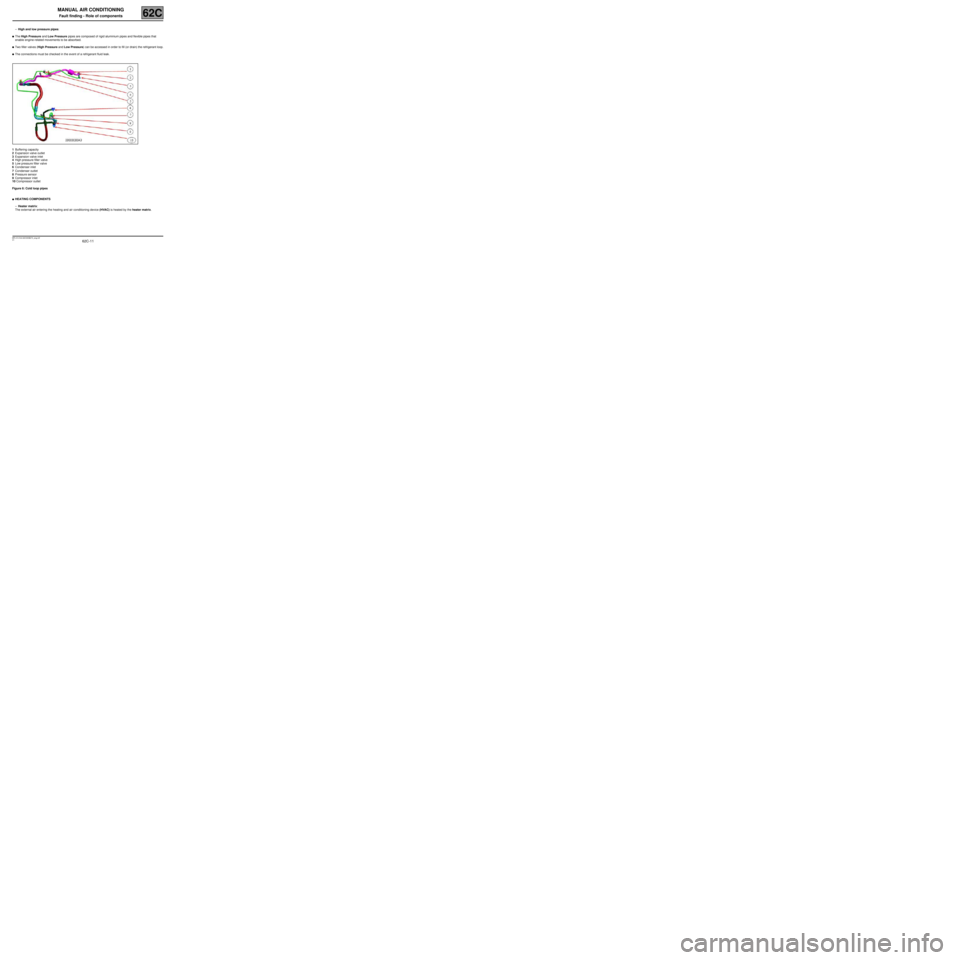
–High and low pressure pipes:
●The High Pressure and Low Pressure pipes are composed of rigid aluminium pipes and flexible pipes that
enable engine-related movements to be absorbed.
●Two filler valves (High Pressure and Low Pressure) can be accessed in order to fill (or drain) the refrigerant loop.
●The connections must be checked in the event of a refrigerant fluid leak.
1Buffering capacity
2Expansion valve outlet
3Expansion valve inlet
4High pressure filler valve
5Low pressure filler valve
6Condenser inlet
7Condenser outlet
8Pressure sensor
9Compressor inlet
10 Compressor outlet
Figure 6: Cold loop pipes
●HEATING COMPONENTS
–Heater matrix:
The external air entering the heating and air conditioning device (HVAC) is heated by the heater matrix.
Page 14 of 63
62C-14
MR-413-X44-62C000$364_eng.mif
V1
62C
MANUAL AIR CONDITIONING
Fault finding - Operating diagram
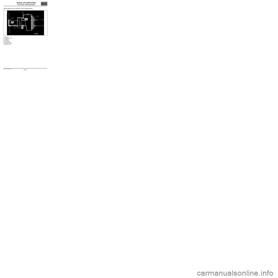
Summary diagram of all the components of the air conditioning system
1Evaporator
2Temperature sensor
3Compressor
4Condenser
5Fan assembly
6Pressure switch
7Dehydration canister
8Expansion valve
MR-413-X44-62C000$364_eng.mif
Page 19 of 63
62C-19
MR-413-X44-62C000$455_eng.mif
V1
MANUAL AIR CONDITIONING
Fault finding - Function62C
Vehicle
multiplex
network
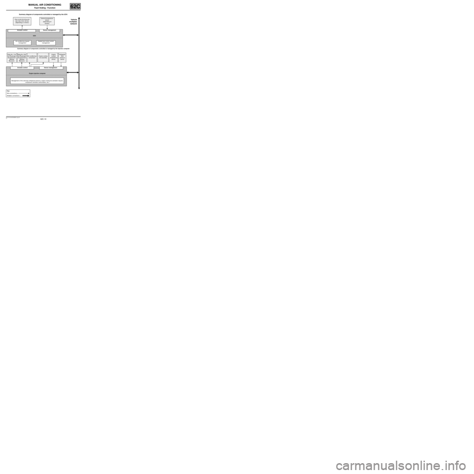
Summary diagram of components controlled or managed by the UCH:
Summary diagram of components controlled or managed by the injection computer Rear screen de-icing and
rear-view mirror de-icer
(depending on version)External temperature
sensor
(depending on
version)
Actuator control Sensor management
UCH
Air conditioning request
managementHeated rear screen control
management
Relay No. 1 for
the Passenger
Compartment
Heating
ResistorsRelay No. 2 for
the Passenger
Compartment
Heating
ResistorsAir conditioning
compressorEngine cooling
fan assemblyEngine
coolant
temperature
sensorRefrigerant
fluid
pressure
sensor
Actuator control Sensor management
Engine injection computer
Management of the cold loop (refrigerant pressure, engine cooling fan activation request,
compressor activation authorisation, etc.)
Key:
Wire connections =
Multiplex connections =
Page 21 of 63
62C-21
MR-413-X44-62C000$546_eng.mif
V1
62C
MANUAL AIR CONDITIONING
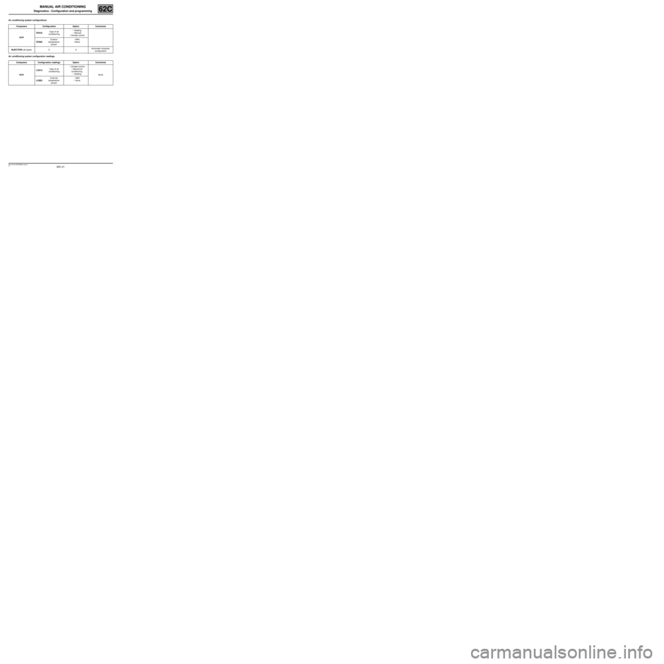
Diagnostics - Configuration and programming
Air conditioning system configurations
Air conditioning system configuration readingsComputers Configuration Option Comments
UCHCF019: Type of air
conditioning– Heating
– Manual
– Climate control
CF029: Exterior
temperature
sensor–With
–None
INJECTION (all types) X XAutomatic computer
configuration
Computers Configuration readings Option Comments
UCHLC013: Type of air
conditioning– Climate control
– Manual air
conditioning
– Heating
None
LC002: External
temperature
sensor– With
– None
MR-413-X44-62C000$546_eng.mif
Page 39 of 63
62C-39
MR-413-X44-62C000$819_eng.mif
V1
MANUAL AIR CONDITIONING
Fault finding - Fault finding charts62C
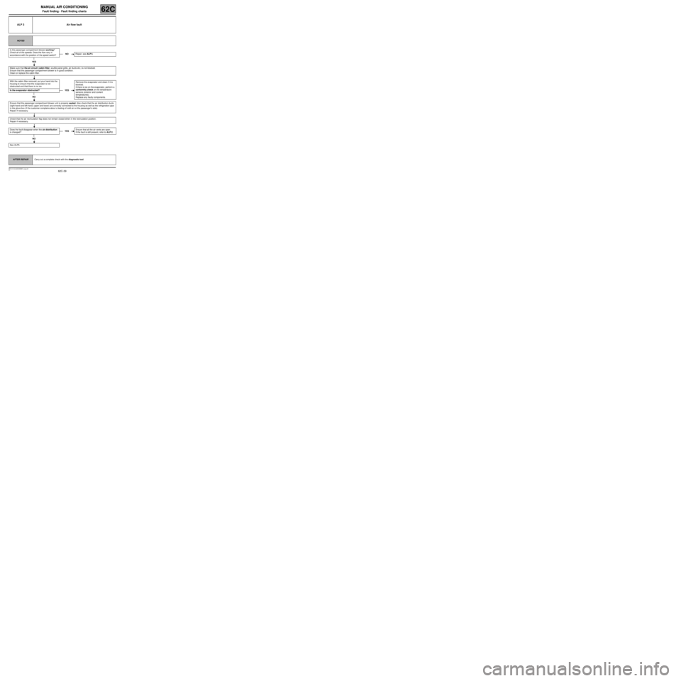
ALP 3 Air flow fault
NOTES
Is the passenger compartment blower working?
Check all of the speeds: Does the flow vary in
accordance with the position of the speed switch?
YES
Make sure that the air circuit (cabin filter, scuttle panel grille, air ducts etc.) is not blocked.
Ensure that the passenger compartment blower is in good condition.
Clean or replace the cabin filter.
With the cabim filter removed, put your hand into the
housing to ensure that the evaporator is not
obstructed and that there is no ice.
Is the evaporator obstructed?
NO
Ensure that the passenger compartment blower unit is properly sealed. Also check that the air distribution ducts
(right-hand and left-hand, upper and lower) are correctly connected to the housing as well as the refrigeration pipe
in the glove box (if the customer complains about a feeling of cold air on the passenger's side).
Repair if necessary.
Check that the air recirculation flap does not remain closed when in the recirculation position.
Repair if necessary.
Does the fault disappear when the air distribution
is changed ?
NO
See ALP5.
AFTER REPAIRCarry out a complete check with the diagnostic tool.
NORepair, see ALP 5.
YESRemove the evaporator and clean if it is
blocked.
If there is ice on the evaporator, perform a
conformity check on the temperature
sensors (exterior and coolant
temperatures).
Replace any faulty components.
YESEnsure that all the air vents are open.
If the fault is still present, refer to ALP 2.
Page 49 of 63
62C-49
MR-413-X44-62C000$819_eng.mif
V1
MANUAL AIR CONDITIONING
Fault finding - Fault finding charts62C
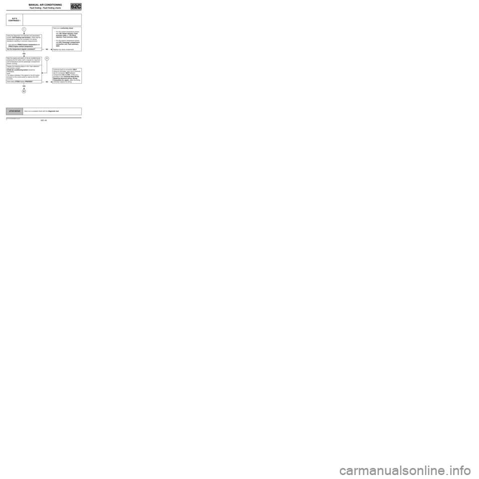
ALP 8
CONTINUED 1
1
Using the diagnostic tool statuses and parameters
screen (UCH heating sub-function), check that the
temperature signals are consistent (no sensor
deviations resulting in incorrect measurement).
–Use statuses PR002 Exterior temperature and
PR024 Engine coolant temperature.
Are the temperature signals consistent?
YES
Start the engine and switch on the air conditioning by
pressing the AC button (with a request for maximum
cold temperature and the passenger compartment
blower running).
2
Display the following status in the “User selection”
sub-function screen:
ET029 Air conditioning button should be
PRESSED.
Note:
The status indicates if the signal for the AC button
pressed on the control panel is read by the UCH
correctly.
Does status ET029 display PRESSED?
YES
NOCarry out a conformity check:
–For the coolant temperature sensor,
see 13B, Diesel injection, Fault
summary table or 17B Petrol
injection, Fault summary table.
–For the exterior temperature sensor,
see 87B, Passenger compartment
connection unit, Fault summary
table.
Replace any faulty components.
NOContinuity fault on connection 38LP.
Using an ohmmeter, carry out a continuity
test on connection 38LP between
components 319 and 645. If there is a
procedure (see Technical Note 6015A,
Repairing electrical wiring, Wiring:
Precautions for repair), repair the wiring,
otherwise replace the wiring.
AFTER REPAIRCarry out a complete check with the diagnostic tool.
Page 57 of 63
62C-57
MR-413-X44-62C000$910_eng.mif
V1
MANUAL AIR CONDITIONING
Fault finding - Fault finding charts62C
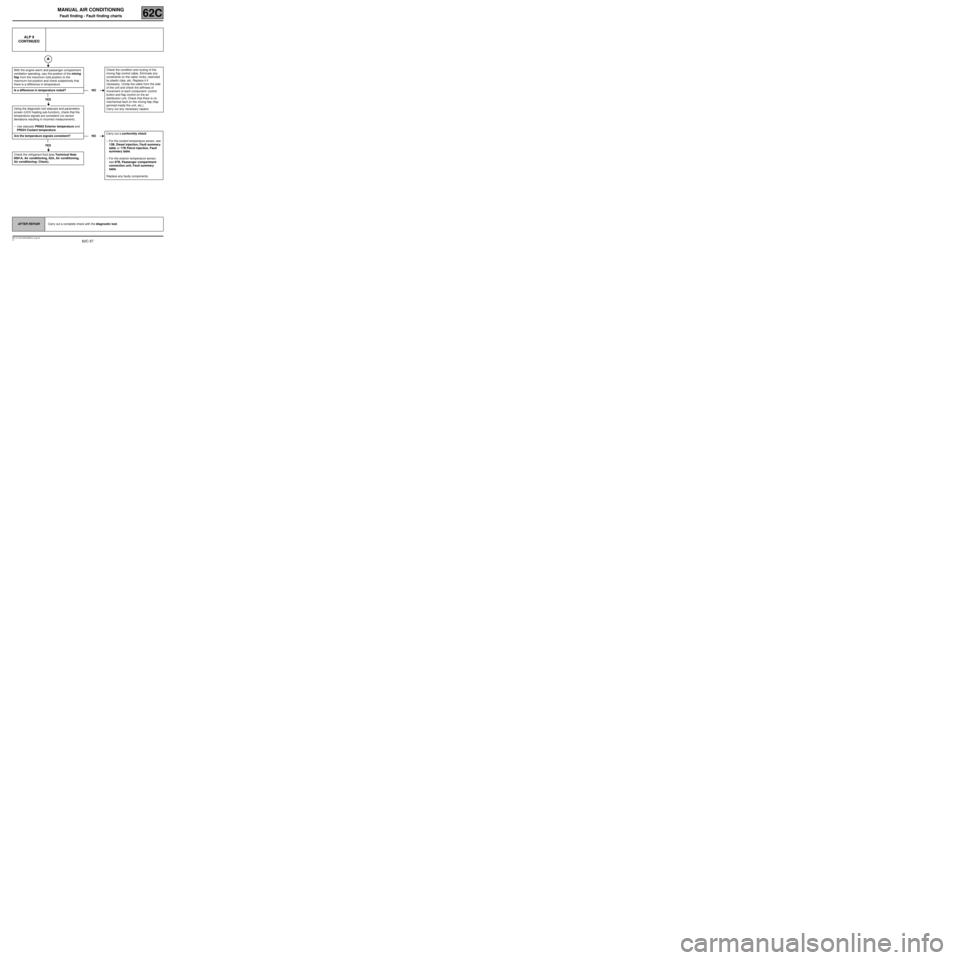
ALP 9
CONTINUED
With the engine warm and passenger compartment
ventilation operating, vary the position of the mixing
flap from the maximum cold position to the
maximum hot position and check subjectively that
there is a difference in temperature.
Is a difference in temperature noted?
YES
Using the diagnostic tool statuses and parameters
screen (UCH heating sub-function), check that the
temperature signals are consistent (no sensor
deviations resulting in incorrect measurement).
–Use statuses PR002 Exterior temperature and
PR024 Coolant temperature.
Are the temperature signals consistent?
YES
Check the refrigerant fluid (see Technical Note
6001A, Air conditioning, 62A, Air conditioning,
Air conditioning: Check).
NOCheck the condition and routing of the
mixing flap control cable. Eliminate any
constraints on the cable: kinks, restricted
by plastic clips, etc. Replace it if
necessary. Unclip the cable from the side
of the unit and check the stiffness of
movement of each component: control
button and flap control on the air
distribution unit. Check that there is no
mechanical fault on the mixing flap (flap
jammed inside the unit, etc.).
Carry out any necessary repairs.
NOCarry out a conformity check:
–For the coolant temperature sensor, see
13B, Diesel injection, Fault summary
table or 17B Petrol injection, Fault
summary table.
–For the exterior temperature sensor,
see 87B, Passenger compartment
connection unit, Fault summary
table.
Replace any faulty components.
AFTER REPAIRCarry out a complete check with the diagnostic tool.