headlight RENAULT TWINGO 2009 2.G Panelwork Workshop Manual
[x] Cancel search | Manufacturer: RENAULT, Model Year: 2009, Model line: TWINGO, Model: RENAULT TWINGO 2009 2.GPages: 209
Page 4 of 209
Contents
Front wing upper mounting
support: Removal - Refi tting 42A-7
Front end panel: General
descr iption 42A-8
Front end panel: Removal -
Refitting 42A-9
Headlight carrier panel:
Removal - Refitting 42A-11
Front upper cross member:
General description 42A-12
Front upper cross member:
Removal - Refitting 42A-13
Scuttle side panel: General
descr iption 42A-14
Scuttle side panel:
Description 42A-16
Upper reinforcement of
scuttle side panel: General
descr iption 42A-18
Upper reinforcement of
scuttle side panel:
Description 42A-19
Front wheel arch: General
descr iption 42A-21
Front wheel arch: Description 42A-22
Front wheel arch, front
section: General description 42A-25
Dashboard cross member:
Removal - Refitting 42A-26
Windscreen aperture lower
cross member closure panel:
Description 42A-28
43A SIDE UPPER STRUCTURE
A-pillar : General description 43A-1
A-pillar : Description 43A-2
A-pillar reinforcement:
General description 43A-5 42A FRONT UPPER STRUCTUREA-pillar reinforcement:
Description 43A-6
Windscreen pillar lining:
General description 43A-8
B-pillar reinforcement:
General description 43A-9
B-pillar reinforcement:
Description 43A-10
Body side: General
descr iption 43A-12
Body side: Description 43A-13
Upper body: General
descr iption 43A-15
Upper body: Description 43A-17
44A REAR UPPER STRUCTURE
Rear wing panel: General
descr iption 44A-1
Rear wing panel: Description 44A-2
Rear lights mounting:
General description 44A-5
Rear lights mounting:
Description 44A-6
Outer rear wheel arch:
General description 44A-8
Outer rear wheel arch:
Description 44A-10
Inner rear wheel arch:
General description 44A-13
Inner rear wheel arch:
Description 44A-14
Quar ter panel lining: General
descr iption 44A-16
Quar ter panel lining:
Description 44A-17
Rear end panel assembly:
Description 44A-22 43A SIDE UPPER STRUCTURE
Page 28 of 209
40A-23
GENERAL INFORMATION
Vehicle structure, removable section: Description
40A
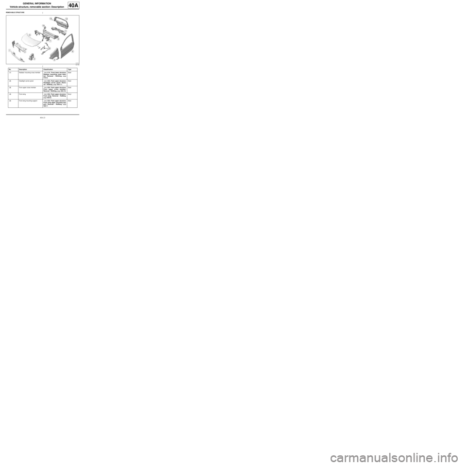
REMOVABLE STRUCTURE
121745
No. Description Classification Type
(1) Radiator mounting cross member (see 41A, Front lower structure,
Radiator mounting cross mem-
ber: Removal - Refitting, page
41A-5) Steel
(2) Headlight carrier panel (see 42A, Front upper structure,
Headlight carrier panel: Remo-
val - Refitting, page 42A-11) Steel
(3) Front upper cross member (see 42A, Front upper structure,
Front upper cross member:
Removal - Refitting, page 42A-13) Steel
(4) Front wing (see 42A, Front upper structure,
Front wing: Removal - Refitting,
page 42A-3) Noryl
(5) Front wing mounting support (see 42A, Front upper structure,
Front wing upper mounting sup-
port: Removal - Refitting, page
42A-7) Steel
Page 110 of 209
42A-1
FRONT UPPER STRUCTURE
Front wing: General description
42A
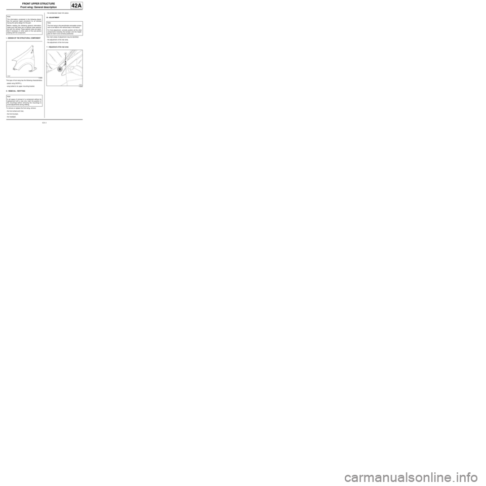
I - DESIGN OF THE STRUCTURAL COMPONENT
This type of front wing has the following characteristics:
-plastic wing (NORYL),
-wing bolted to its upper mounting bracket.
II - REMOVAL - REFITTING
To remove or replace the front wing, remove:
-the front wheel arch liner,
-the front bumper,
-the headlight,-the windscreen lower trim piece.
III - ADJUSTMENT
Two main areas of adjustment may be identified:
-the adjustment of the rear area,
-the adjustment of the front area
1 - Adjustment of the rear area: Note:
The information contained in the following descri-
bes the general repair procedure for all vehicles
having the same design for this part.
Before reading the following general information,
make sure that there are no special notes associa-
ted with the vehicle. These special notes are speci-
fied if necessary in other par ts of the sub-section
dealing with the component.
112606
Note:
In all cases of removal of a component without its
replacement with a new one, mark the position of
the mountings before removing the mountings to
avoid adjustments during refitting.
Note:
The front wing is the penultimate removable compo-
nent to be fitted to the vehicle body in the factory.
For final adjustment, correctly position all the other
components including the bumper and the headli-
ghts for them to be correctly positioned.
112042
Page 112 of 209
42A-3
FRONT UPPER STRUCTURE
Front wing: Removal - Refitting
42A
REMOVAL
I - REMOVAL PREPARATION OPERATION
aRemove:
-the front wheel arch liner (see Front wheel arch
liner: Removal - Refitting) (MR 412, 55A, Exterior
protection),
-the front bumper (see Front bumper: Removal -
Refitting) (MR 412, 55A, Exterior protection),
-the halogen headlight (see Halogen headlight:
Removal - Refitting) (MR 411, 80B, Headlights).
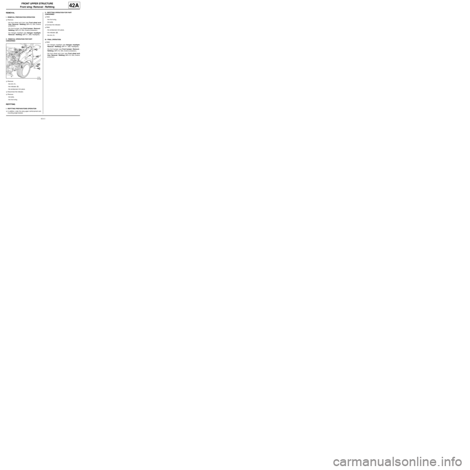
II - REMOVAL OPERATION FOR PART
CONCERNED
aRemove:
-the trim (1) ,
-the indicator (2) ,
-the windscreen trim piece.
aDisconnect the indicator.
aRemove:
-the bolts,
-the front wing.
REFITTING
I - REFITTING PREPARATIONS OPERATION
aIn addition, order the wing upper reinforcement and
mounting angle bracket.II - REFITTING OPERATION FOR PART
CONCERNED
aRefit:
-the front wing,
-the bolts.
aConnect the indicator.
aRefit:
-the windscreen trim piece,
-the indicator (2) ,
-the trim (1) .
III - FINAL OPERATION.
aRefit:
-the halogen headlight (see Halogen headlight:
Removal - Refitting) (MR 411, 80B, Headlights),
-the front bumper (see Front bumper: Removal -
Refitting) (MR 412, 55A, Exterior protection),
-the front wheel arch liner (see Front wheel arch
liner: Removal - Refitting) (MR 412, 55A, Exterior
protection).
121198
Page 114 of 209
42A-5
FRONT UPPER STRUCTURE
Front wing: Adjustment
42A
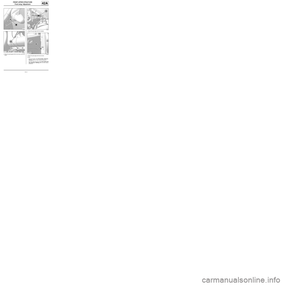
aAdjust the panel gaps with the front door and the sill
panel.aAdjust the panel gaps with the headlight.
aAdjust the panel gaps with the front door.
aRefit:
-the front bumper (see Front bumper: Removal -
Refitting) (MR 412, 55A, Exterior protection),
-the front wheel arch liner (see Front wheel arch
liner: Removal - Refitting) (MR 412, 55A, Exterior
protection).
121235
121234121233
121236
Page 116 of 209
42A-7
FRONT UPPER STRUCTURE
Front wing upper mounting support: Removal - Refitting42A
REMOVAL
I - REMOVAL PREPARATION OPERATION
aRemove:
-the front wheel arch liner (see Front wheel arch
liner: Removal - Refitting) (MR 412, 55A, Exterior
protection),
-the front bumper (see Front bumper: Removal -
Refitting) (MR 412, 55A, Exterior protection),
-the halogen headlight (see Halogen headlight:
Removal - Refitting) (MR 411, 80B, Headlights),
-the front wing (see 42A, Front upper structure,
Front wing: Removal - Refitting, page 42A-3) .
II - OPERATION FOR REMOVAL OF PART
CONCERNED
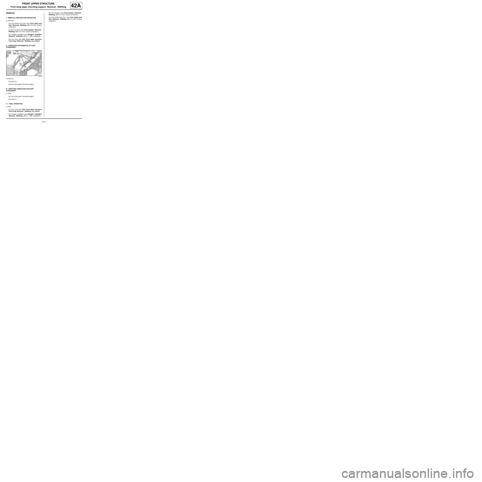
aRemove:
-the bolts (1) ,
-the front wing upper mounting support ,
III - REFITTING OPERATION FOR PART
CONCERNED
aRefit:
-the front wing upper mounting support,
-the bolts (1) .
IV - FINAL OPERATION.
aRefit:
-the front wing (see 42A, Front upper structure,
Front wing: Removal - Refitting, page 42A-3) ,
-the halogen headlight (see Halogen headlight:
Removal - Refitting) (MR 411, 80B, Headlights),-the front bumper (see Front bumper: Removal -
Refitting) (MR 412, 55A, Exterior protection),
-the front wheel arch liner (see Front wheel arch
liner: Removal - Refitting) (MR 412, 55A, Exterior
protection).
121237
Page 118 of 209
42A-9
FRONT UPPER STRUCTURE
Front end panel: Removal - Refitting
42A
REMOVAL
I - REMOVAL PREPARATION OPERATION
aRemove:
-the front bumper ( (see Front bumper: Removal -
Refitting) ),
-the headlights ( (see Halogen headlight: Remo-
val - Refitting) ),
-the bonnet catch ( (see Bonnet lock: Removal -
Refitting) ).
II - OPERATION FOR REMOVAL OF PART
CONCERNED
aUnclip the wiring harness.
aRemove the bonnet opening cable.
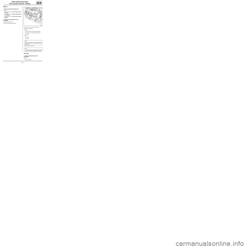
aRemove the bolt (1) from the coolant bottle.
aUnclip the coolant bottle.
aRemove:
-the bolt (2) from the cooling radiator deflector,
-the bolts (3) from the cooling radiator support,
-the bolts (4) .
aUndo:
-the nut (5) ,
-the bolts (6) .
aRemove the front end panel.
REFITTING
I - REFITTING OPERATION FOR PART
CONCERNED
aRefit:
-the front end panel,
121037
Note:
The bolts (4) and (6) can be accessed between
the front end lower cross member and the coo-
ling radiator.
Note:
The front end panel is made up of the front upper
cross member and the headlight carrier panels.
Page 119 of 209
42A-10
FRONT UPPER STRUCTURE
Front end panel: Removal - Refitting
42A
-the bolts (4) ,
-the bolts (3) on the cooling radiator support,
-the bolt (2) on the cooling radiator deflector.
aTighten:
-The bolts (6) ,
-the nut (5) .
aClip on the coolant bottle.
aRefit the bolt (1) on the coolant bottle.
aPosition the bonnet opening release cable.
aClip on the wiring harness.
II - FINAL OPERATION.
aRefit:
-the bonnet catch ( (see Bonnet lock: Removal -
Refitting) ),
-the headlights ( (see Halogen headlight: Remo-
val - Refitting) ),
-the front bumper ( (see Front bumper: Removal -
Refitting) ).
Page 120 of 209
42A-11
FRONT UPPER STRUCTURE
Headlight carrier panel: Removal - Refitting
42A
REMOVAL
I - REMOVAL PREPARATION OPERATION
aRemove:
-the front bumper (see Front bumper: Removal -
Refitting) (MR 412, 55A, Exterior protection),
-the halogen headlight (see Halogen headlight:
Removal - Refitting) (MR 411, 80B, Headlights),
-the bonnet catch (see Bonnet lock: Removal -
Refitting) (MR 412, 52A, Non-side opening ele-
ment mechanisms),
-the front upper cross member (see 42A, Front up-
per structure, Front upper cross member: Re-
moval - Refitting, page 42A-13) .
II - OPERATION FOR REMOVAL OF PART
CONCERNED
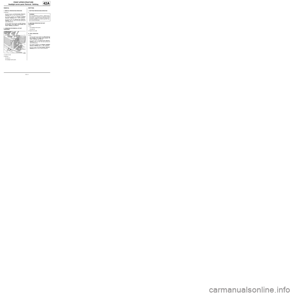
aLoosen nut (2) .
aRemove:
-the bolts (1) ,
-the headlight carrier panel.
REFITTING
I - REFITTING PREPARATIONS OPERATION
a
II - REFITTING OPERATION FOR PART
CONCERNED
aRefit:
-the headlight carrier panel,
-the bolts (1) .
aTighten the nut (2) .
III - FINAL OPERATION.
aRefit:
-the front upper cross member (see 42A, Front up-
per structure, Front upper cross member: Re-
moval - Refitting, page 42A-13) ,
-the bonnet catch (see Bonnet lock: Removal -
Refitting) (MR 412, 52A, Non-side opening ele-
ment mechanisms),
-the halogen headlight (see Halogen headlight:
Removal - Refitting) (MR 411, 80B, Headlights),
-the front bumper (see Front bumper: Removal -
Refitting) (MR 412, 55A, Exterior protection).
121251
WARNING
For any adjustment or removal - refitting proce-
dure where it is necessar y to separate a bolted
connection, reapply the mating and sealing anti-
corrosion protection to the bolts using filler mas-
tic in a pre-formed bead.
Page 121 of 209
42A-12
FRONT UPPER STRUCTURE
Front upper cross member: General description
42A
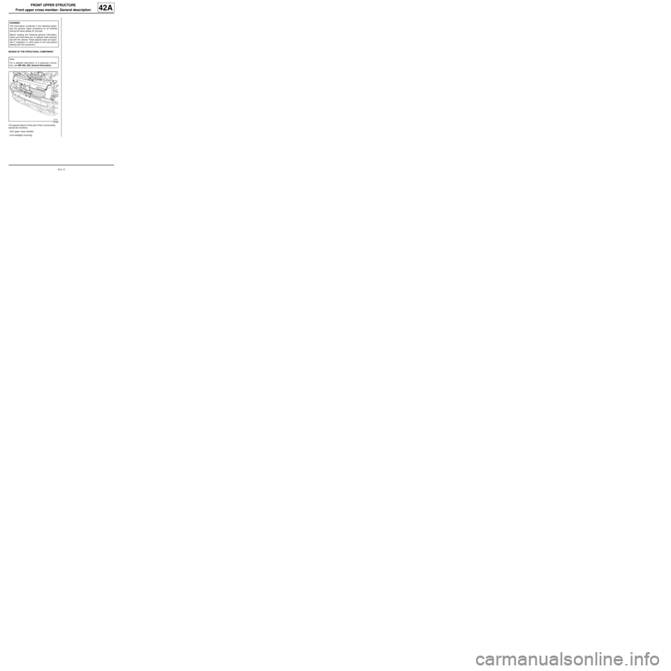
DESIGN OF THE STRUCTURAL COMPONENT
The special feature of this part it that it concurrently
serves two functions:
-front upper cross member,
-front headlight mounting. WARNING
The information contained in the following descri-
bes the general repair procedure for all vehicles
having the same design for this part.
Before reading the following general information,
make sure that there are no special notes associa-
ted with the vehicle. These special notes are speci-
fied if necessary in other par ts of the sub-section
dealing with the component.
Note:
For a detailed description of a particular connec-
tion, see MR 400, 40A, General Information.
121036