relay RENAULT TWINGO RS 2009 2.G Chasiss ESP Workshop Manual
[x] Cancel search | Manufacturer: RENAULT, Model Year: 2009, Model line: TWINGO RS, Model: RENAULT TWINGO RS 2009 2.GPages: 101
Page 11 of 101
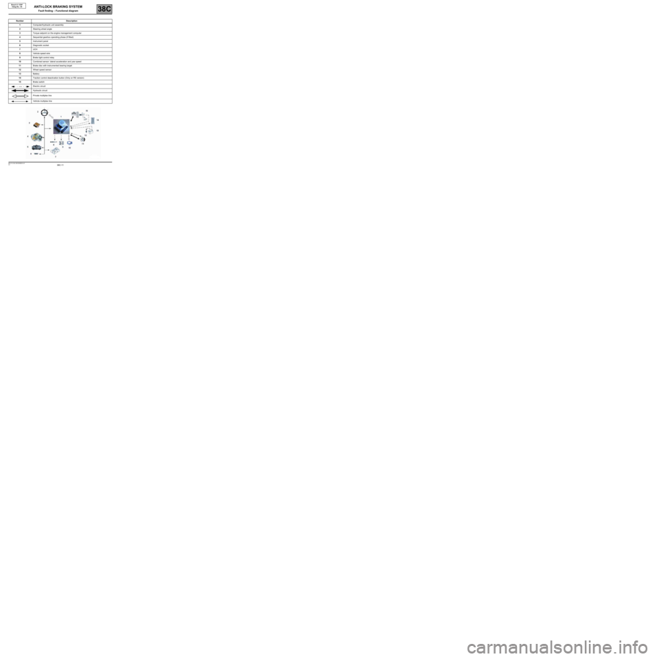
38C-11V3 MR-413-X44-38C050$030.mif
38C
Bosch 8.1 ESP
Vdiag No.: 05
Number Description
1Computer/hydraulic unit assembly
2Steering wheel angle
3Torque setpoint on the engine management computer
4Sequential gearbox operating phase (if fitted)
5Instrument panel
6Diagnostic socket
7 UCH
8Vehicle speed wire
9Brake light control relay
10Combined sensor: lateral acceleration and yaw speed
11Brake disc with instrumented bearing target
12Wheel speed sensor
13Battery
14Traction control deactivation button (Only on RS version)
15Brake switch
Electric circuit
Hydraulic circuit
Private multiplex line
Vehicle multiplex line
ANTI-LOCK BRAKING SYSTEM
Fault finding – Functional diagram
Page 18 of 101

38C-18V3 MR-413-X44-38C050$090.mif
ANTI-LOCK BRAKING SYSTEM
Fault finding – Fault summary table38C
Bosch 8.1 ESP
Vdiag No.: 05
* inj: InjectionTool faultAssociated
DTCDiagnostic tool title
DF100 5158Steering wheel angle multiplex signal absent
DF108 5158Steering wheel angle sensor
DF126 50F4Combined sensor signal plausibility
DF152 50E6Multiplex network
DF153 50C3Multiplex network
DF186 5182No instrument panel multiplex signal
DF187 50CEBrake light activation relay circuit
DF188 50C6Brake light switch circuit
DF189 50F4Combined sensor circuit
DF190 50F4Combined sensor
DF191 50C9ESP on/off button circuit (only on RS version)
DF193 5180Invalid inj.* multiplex signals
DF202 5183Invalid UCH multiplex signals
DF216 5158Steering wheel angle programming offset
DF300 50CAPump motor control circuit
DF311 5188No sequential gearbox multiplex signal (depending on vehicle)
DF313 5188Invalid sequential gearbox multiplex signals (depending on vehicle)
DF321 5180Clutch switch signal consistency
Page 49 of 101
38C-49
AFTER REPAIRClear the computer fault memory.
Carry out a road test followed by another check with the diagnostic tool
If the fault is still present, contact the Techline.
V3 MR-413-X44-38C050$101.mif
ANTI-LOCK BRAKING SYSTEM
Fault finding – Interpretation of faults38C
Bosch 8.1 ESP
Vdiag No.: 05
DF099
PRESENT
OR
STOREDPRIVATE MULTIPLEX NETWORK
NOTESUse the Wiring Diagram Technical Note for New Twingo.
Check the connection and condition (possible wiring damage) of the connectors of components 1094 and 1175.
If the connector is faulty (see Technical Note 6015A, Repairing electrical wiring, Wiring: Precautions
for repair), repair the connector, otherwise replace the wiring.
Check for a voltage of 12 V between connections MAM and AP5 of component 1175.
Is the voltage measured correct?
YESConnector of component 583 and intermediate union R107 disconnected.
Check the insulation and continuity of connections 4AP and 4AH between
component 1175 and the intermediate union R107.
Check the insulation and continuity of connections 4AP and 4AH between
intermediate union R107 and component 1094.
If the connections are faulty (see Technical Note 6015A, Electrical wiring repair,
Wiring: Precautions for repair), repair the wiring, otherwise replace it.
If the checks do not reveal any faults, replace component 1175 (see MR 411,
Mechanical, 38C, Anti-lock braking system, Lateral acceleration and yaw speed
sensor, Removal - Refitting).
NOCheck the condition and position of fuse F10 (5A) in the passenger compartment
fuse and relay box (see 81C, Fuse box).
Connectors of components 1175, 583, 1094 and intermediate union R107
disconnected.
Check the insulation and continuity of connection MAM of component 1175.
Check the insulation and continuity of connection AP5 between
components 1016 and 1175.
Check the insulation and continuity of connection AP5 between component 1094
and intermediate union R107.
If the connections are faulty (see Technical Note 6015A, Electrical wiring repair,
Wiring: Precautions for repair), repair the wiring, otherwise replace it.
ESP_V05_DF099
Page 56 of 101
38C-56
AFTER REPAIRClear the computer fault memory.
Carry out a road test followed by another check with the diagnostic tool
If the fault is still present, contact the Techline.
V3 MR-413-X44-38C050$101.mif
ANTI-LOCK BRAKING SYSTEM
Fault finding – Interpretation of faults38C
Bosch 8.1 ESP
Vdiag No.: 05
DF187
PRESENT
OR
STOREDBRAKE LIGHT ACTIVATION RELAY CIRCUIT
DEF: open circuit or short circuit
NOTESSpecial notes:
If this fault appears after running command AC187 Brake light activation relay,
ignore this fault.
Use the Wiring Diagram Technical Note for New Twingo.
Are the brake lights continuously lit?
YESConnector of components 1281, 1094 and intermediate union R107 disconnected,
Check the insulation to earth of connection 4GJ between component 1281
and intermediate union R107.
Check the insulation to earth of connection 4GJ between intermediate union R107
and component 1094.
If the connections are faulty (see Technical Note 6015A, Electrical wiring repair,
Wiring: Precautions for repair), repair the wiring, otherwise replace it.
If all these checks are in order, replace component 1281.
ESP_V05_DF187
Page 78 of 101
38C-78
AFTER REPAIRClear the computer fault memory.
Carry out a road test followed by another check with the diagnostic tool.
V3 MR-413-X44-38C050$150.mif
38C
Bosch 8.1 ESP
Vdiag No.: 05
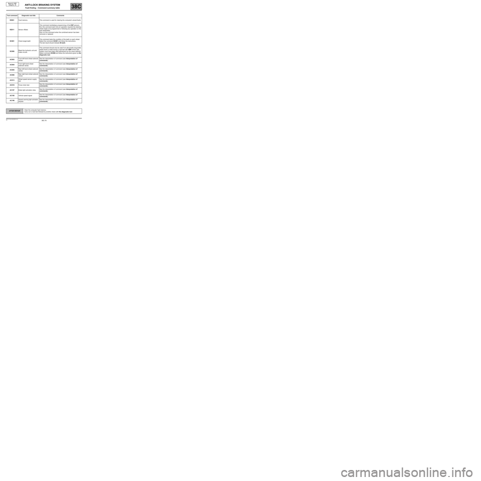
Tool command Diagnostic tool title Comments
RZ001Fault memory This command is used for clearing the computer's stored faults
RZ011Sensor offsetsThis command reinitialises programming of the ESP sensors.
Run this command each time an operation required the steering
wheel angle to be programmed or following any operation on the
axle assemblies.
Also run this command when the combined sensor has been
removed or replaced
SC001Check target teethThis command tests the condition of the teeth on each wheel.
Select the command SC001 and follow the instructions.
The test result should indicate 48 teeth.
SC006Bleed the hydraulic unit and
brake circuitsThis command should only be used if an abnormally long brake
pedal travel is noted during a road test with ABS control (the
system must have been bled beforehand by the usual method).
Select command SC006 and follow the instructions given by the
diagnostic tool.
AC003Front left-hand wheel solenoid
valvesSee the interpretation of command (see Interpretation of
commands).
AC004Front right-hand wheel
solenoid valvesSee the interpretation of command (see Interpretation of
commands).
AC005Rear left-hand wheel solenoid
valvesSee the interpretation of command (see Interpretation of
commands).
AC006Rear right-hand wheel solenoid
valvesSee the interpretation of command (see Interpretation of
commands).
AC013Wheel speed sensor supply
testSee the interpretation of command (see Interpretation of
commands).
AC016Pump motor testSee the interpretation of command (see Interpretation of
commands).
AC187Brake light activation relaySee the interpretation of command (see Interpretation of
commands).
AC195Vehicle speed signalSee the interpretation of command (see Interpretation of
commands).
AC196Hazard warning light activation
requestSee the interpretation of command (see Interpretation of
commands).
ANTI-LOCK BRAKING SYSTEM
Fault finding – Command summary table
Page 82 of 101
38C-82
AFTER REPAIRClear the computer fault memory.
Carry out a road test followed by another check with the diagnostic tool.
V3 MR-413-X44-38C050$160.mif
ANTI-LOCK BRAKING SYSTEM
Fault finding – Interpretation of commands38C
Bosch 8.1 ESP
Vdiag No.: 05
AC187BRAKE LIGHT ACTIVATION RELAY
NOTESConditions of use of the command.
Ignition on, engine off.
This command is used to test brake light activation by the ESP when controlling oversteer with sharp deceleration.
ESP_V05_AC187
Page 99 of 101
38C-99
AFTER REPAIRClear the computer fault memory.
Carry out a road test followed by another check with the diagnostic tool.
V3 MR-413-X44-38C050$180.mif
ANTI-LOCK BRAKING SYSTEM
Fault finding – Fault finding chart38C
Bosch 8.1 ESP
Vdiag No.: 05
ALP 13 Faulty brake light illumination
NOTESOnly address this customer complaint after a complete check with the diagnostic tool.
Using the diagnostic tool, check the consistent status ET017 "Brake pedal" for pedal pressed and pedal
released.
If inconsistent, apply the fault finding procedure for status ET017 Brake pedal.
If the lights come on continuously, check the operation of component 1281 using command AC187 Brake light
activation relay. The brake lights must light only when the command is run.
Otherwise, with component 1281 removed, check the continuity between connections 65A and 65G of
component 1281.
If continuity is not guaranteed, replace component 1281.
ESP_V05_ALP13