steering RENAULT TWINGO RS 2009 2.G Chasiss User Guide
[x] Cancel search | Manufacturer: RENAULT, Model Year: 2009, Model line: TWINGO RS, Model: RENAULT TWINGO RS 2009 2.GPages: 281
Page 44 of 281
31A-1
FRONT AXLE COMPONENTS
Front brake pads: Removal - Refitting
EQ UIPMENT LEVEL EA0 or EQUIPMENT LEVEL EA1 or EQUIPMENT LEVEL EA3 or EQUIPMENT LEVEL EA5
or EQUIPMENT LEVEL EAG or EQUIPMENT LEVEL EZ2 or EQUIPMENT LEVEL EZ4
31A
When replacing brake pads, be sure to replace the
pads on the opposite side.
REMOVAL
I - OPERATION FOR REMOVAL OF PART
CONCERNED
aPosition the vehicle on a two-post lift (see Vehicle:
Towing and lifting) .
aSwitch off the ignition without removing the key to
keep the steering column unlocked.
aRemove the front wheels (see 35A, Wheels and ty-
res, Wheel: Removal - Refitting, page 35A-1) .
II - OPERATION FOR REMOVAL OF PART
CONCERNED
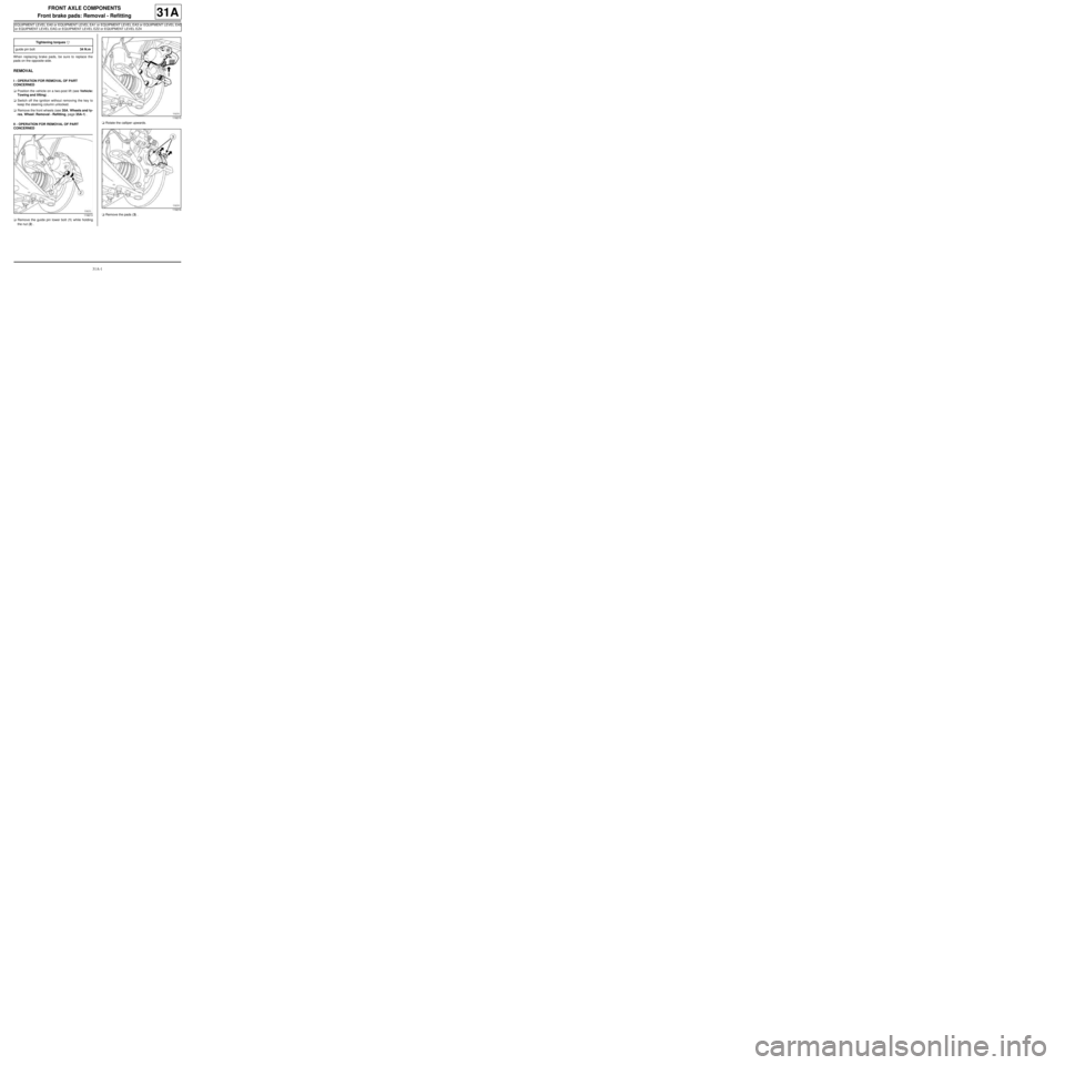
aRemove the guide pin lower bolt (1) while holding
the nut (2) .aRotate the calliper upwards.
aRemove the pads (3) . Tightening torquesm
guide pin bolt34 N.m
119213
119215
119216
Page 51 of 281
31A-8
FRONT AXLE COMPONENTS
Front brake calliper: Removal - Refitting
EQ UIPMENT LEVEL EA0 or EQUIPMENT LEVEL EA1 or EQUIPMENT LEVEL EA3 or EQUIPMENT LEVEL EA5
or EQUIPMENT LEVEL EAG or EQUIPMENT LEVEL EZ2 or EQUIPMENT LEVEL EZ4
31A
REMOVAL
I - REMOVAL PREPARATION OPERATION
aPosition the vehicle on a two-post lift (see Vehicle:
Towing and lifting) .
aFit the pedal press to the brake pedal to limit the
outflow of brake fluid.
aUnlock the steering column.
aRemove the front wheel on the side concerned (see
35A, Wheels and tyres, Wheel: Removal - Refit-
ting, page 35A-1) .II - OPERATION FOR REMOVAL OF PART
CONCERNED
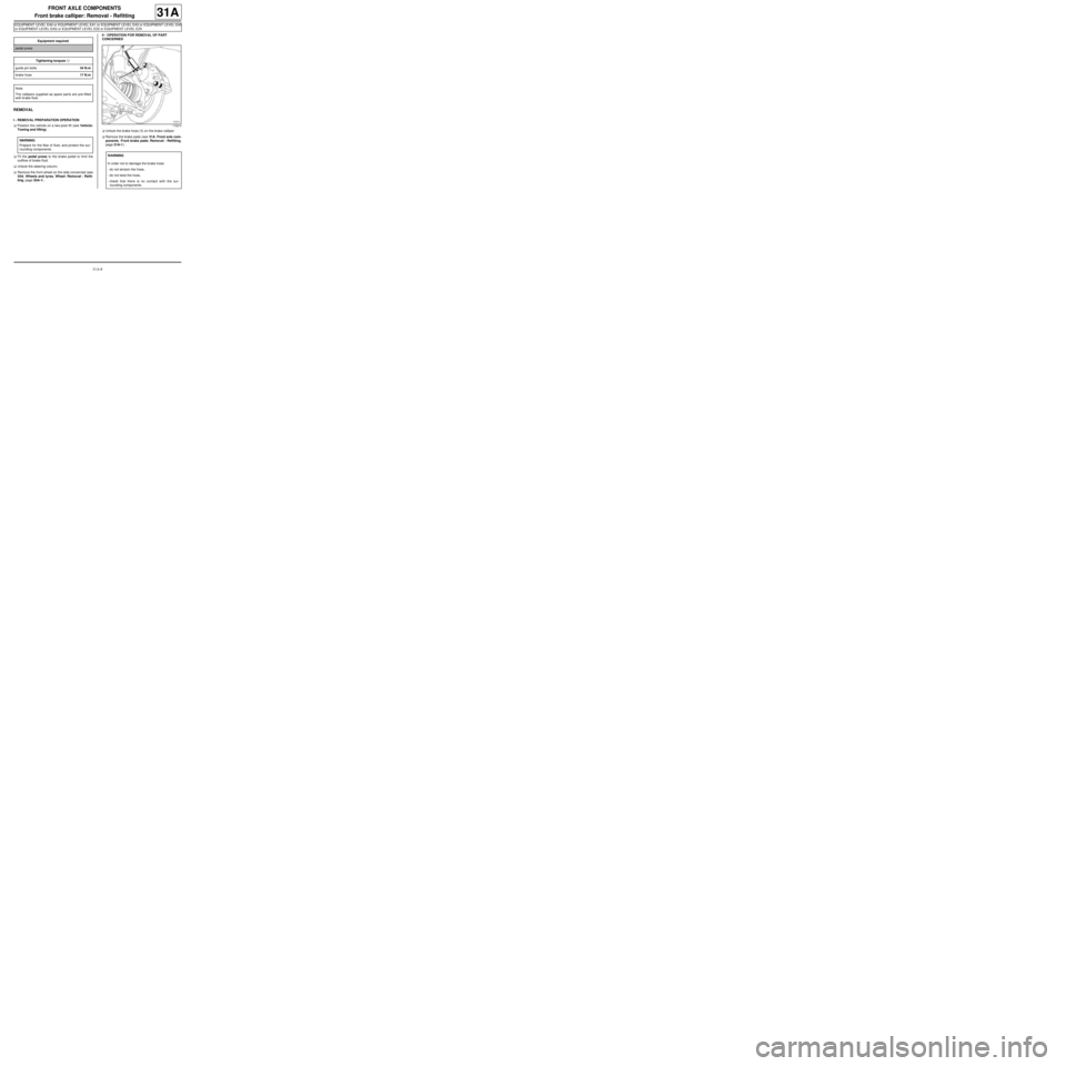
aUnlock the brake hose (1) on the brake calliper.
aRemove the brake pads (see 31A, Front axle com-
ponents, Front brake pads: Removal - Refitting,
page 31A-1) . Equipment required
pedal press
Tightening torquesm
guide pin bolts34 N.m
brake hose17 N.m
Note:
The callipers supplied as spare par ts are pre-filled
with br ake fluid.
WARNING
Prepare for the flow of fluid, and protect the sur-
rounding components.
119214
WARNING
In order not to damage the brake hose:
-do not tension the hose,
-do not twist the hose,
-check that there is no contact with the sur-
rounding components.
Page 86 of 281
31A-43
FRONT AXLE COMPONENTS
Front axle subframe: Removal - Refitting
31A
REMOVAL
I - REMOVAL PREPARATION OPERATION
aPosition the vehicle on a two-post lift (see Vehicle:
Towing and lifting) (02A, Lifting equipment).
aRemove:
-the front wheels (see 35A, Wheels and tyres,
Wheel: Removal - Refitting, page 35A-1) ,
-the front wheel arch liners (see Front wheel arch
liner: Removal - Refitting) (55A, Exterior protec-
tion).II - OPERATION FOR REMOVAL OF PART
CONCERNED
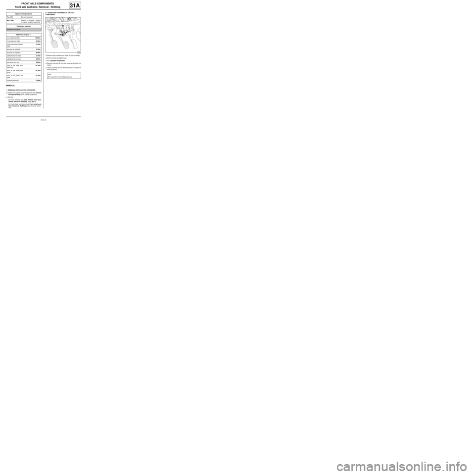
aRemove the universal joint cover (1) (do not keep).
aSet the wheels straight ahead.
aFit a flywheel immobiliser.
aRemove the bolt (2) from the universal joint (do not
keep).
aTilt the universal joint on the steering box to detach it
from the pinion. Special tooling required
Tav. 476Ball joint extractor.
Mot. 1390Suppor t for removal - refitting
of engine - gearbox assembly
Equipment required
flywheel immobiliser
Tightening torquesm
rear subframe bolts105 Nm
front subframe bolts62 Nm
front end cross member
bolts21 Nm
acoustic tie-rod bolts21 Nm
acoustic tie-rod bolts90 Nm
subframe tie-rod bolts21 Nm
subframe tie-rod nuts62 Nm
gear lever arm nut28 Nm
nuts of the lower arm
ball joints62 N.m
bolts of the lower ball
joints62 N.m
nuts of the track rod
ends37 N.m
universal joint bolt24 Nm
119544
Note:
Do not pull the intermediate shaft out.
Page 90 of 281
31A-47
FRONT AXLE COMPONENTS
Front axle subframe: Removal - Refitting
31A
aRemove:
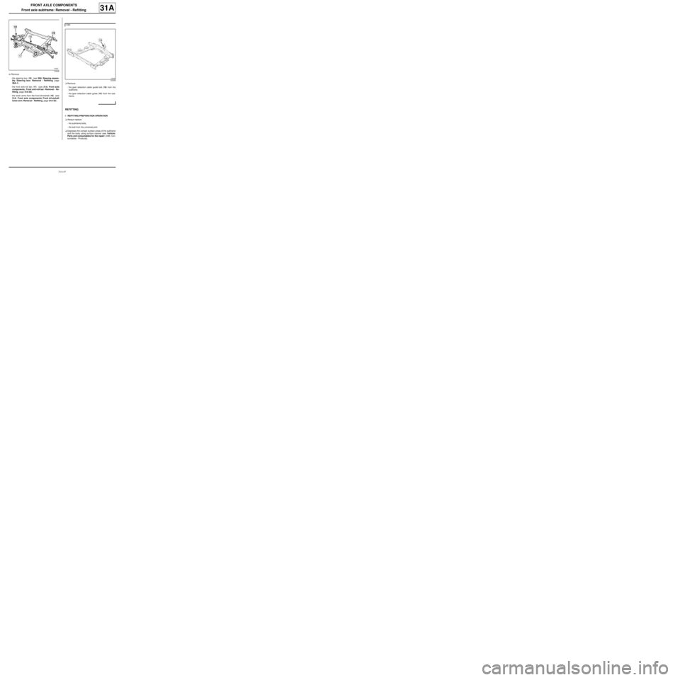
-the steering box (16) (see 36A, Steering assem-
bly, Steering box: Removal - Refitting, page
36A-1) ,
-the front anti-roll bar (17) (see 31A, Front axle
components, Front anti-roll bar: Removal - Re-
fitting, page 31A-52) ,
-the lower arms from the front driveshaft (18) (see
31A, Front axle components, Front driveshaft
lower arm: Removal - Refitting, page 31A-33) .aRemove:
-the gear selection cable guide bolt (19) from the
subframe,
-the gear selection cable guide (19) from the sub-
frame.
REFITTING
I - REFITTING PREPARATION OPERATION
aAlways replace:
-the subframe bolts,
-the bolt from the universal joint.
aDegrease the contact surface areas of the subframe
and the body using surface cleaner (see Vehicle:
Parts and consumables for the repair) (04B, Con-
sumables - Products).
119429
K9K
124348
Page 91 of 281
31A-48
FRONT AXLE COMPONENTS
Front axle subframe: Removal - Refitting
31A
II - REFITTING OPERATION FOR PART
CONCERNED
aRefit the speed selection cable guide on the sub-
frame.
aRefit:
-the front driveshaft lower arms (see 31A, Front
axle components, Front driveshaft lower arm:
Removal - Refitting, page 31A-33) ,
-the front anti-roll bar (see 31A, Front axle compo-
nents, Front anti-roll bar: Removal - Refitting,
page 31A-52) ,
-the steering box (see 36A, Steering assembly,
Steering box: Removal - Refitting, page 36A-1) .
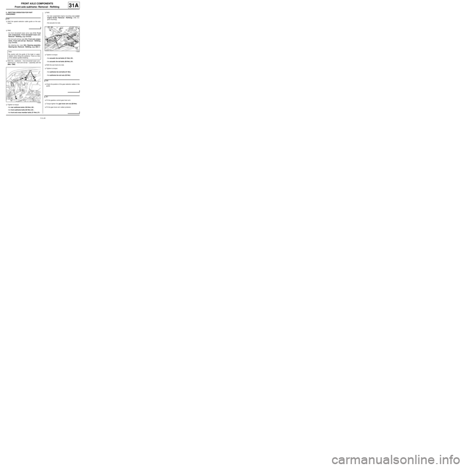
aRefit the « subframe - front driveshaft lower arm -
steering box - front anti-roll bar » assembly with the
(Mot. 1390).
aTighten to torque:
-the rear subframe bolts (105 Nm) (20) ,
-the front subframe bolts (62 Nm) (22) ,
-the front end cross member bolts (21 Nm) (21) .aRefit:
-the rear suspended engine mounting (see Lower
engine tie-bar: Removal - Refitting) (19D, En-
gine mounting),
-the acoustic tie rods.
aTighten to torque:
-the acoustic tie-rod bolts (21 Nm) (23) ,
-the acoustic tie-rod bolts (90 Nm) (24) .
aRefit the sub-frame tie-rods.
aTighten to torque:
-the subframe tie-rod bolts (21 Nm),
-the subframe tie-rod nuts (62 Nm).
aCheck the position of the gear selection cables in the
guide.
aFit the gearbox control gear lever arm.
aTorque tighten the gear lever arm nut (28 Nm).
aFit the gear lever arm rubber protector. K9K
Note:
Be careful with the guide of the lower or upper
radiator when fitting the subframe. There is a risk
of the radiator guides breaking.
119336
119335
K9K
JB1
Page 92 of 281
31A-49
FRONT AXLE COMPONENTS
Front axle subframe: Removal - Refitting
31A
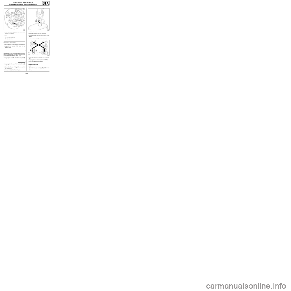
aCheck that the bush (25) is correctly positioned on
the lower arm ball joint.
aRefit:
-the lower arm ball joints,
-the track rod ends.
aRefit the anti-roll bar tie-rods to the shock absorbers.
aTorque tighten the nuts of the lower arm ball
joints (62 N.m).
aTorque tighten the bolts of the lower ball joints (62
N.m).
aTorque tighten the nuts of the track rod ends (37
N.m).
aObserve the direction of fitting for the universal joint
cam nut and bolt.
afit the universal joint to the steering box.aRefit the universal joint cam nut and a new bolt.
aPosition the universal joint cam nut and bolt.
aImmobilise the cam nut in its housing (on the univer-
sal joint).
aPretighten the universal joint cam nut and bolt.
aCheck that the universal joint is in the correct posi-
tion.
aTorque tighten the universal joint bolt (24 Nm).
aRemove the flywheel immobiliser.
III - FINAL OPERATION.
aRefit:
-the front wheel arch liners (see Front wheel arch
liner: Removal - Refitting) (55A, Exterior protec-
tion),
119223
EQ UIPMENT LEVEL SPORT
EQUIPMENT LEVEL EA0 or EQUIPMENT LEVEL
EA1 or EQUIPMENT LEVEL EA3 or EQUIPMENT
LEVEL EA5 or EQUIPMENT LEVEL EAG
116021
116022
Page 144 of 281
35A-4
WHEELS AND TYRES
Wheel: Balancing
35A
I - PREREQUISITES FOR WHEEL BALANCING
aWheel balancing is a measurement operation.
Several conditions must be met to achieve a reliable
result in a single operation.
The wheel balancer must be installed in accordance
with the manufacturer's instructions.
It is essential to calibrate the balancer according to
the frequency recommended by the manufacturer.
Do not grease the threaded shaft.
Check the condition of the supports, centring com-
ponents and mountings.
Replace any faulty parts (see manufacturer's in-
structions).
The wheel and the wheel balancer must be clean.
Driver's perception
aIf the wheels are not correctly balanced this causes
the steering wheel and/or the vehicle floor to vibrate.
These vibrations appear between 54 mph (90 km/h)
and 90 mph (150 km/h).
II - BALANCING PREPARATION OPERATION
aAdjust the tyre pressure (see 35A, Wheels and ty-
res, Tyre pressure: Identification, page 35A-10) .
aAlways carry out a road test for a minimum distance
of 1 mile (2 km) before balancing the wheels, in or-
der to remove any flat spots on the tread caused by
the vehicle being immobilised.
aActions to be carried out immediately after the test
drive:
-Position the vehicle on a two-post vehicle lift (see
Vehicle: Towing and lifting) ,
-raise the vehicle,
-leave the four wheels hanging free,
-release the parking brake.a
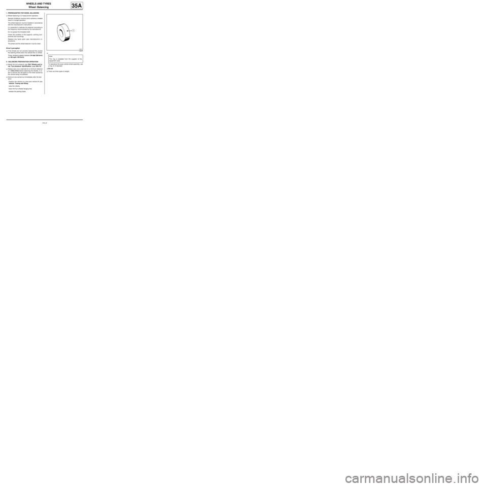
To reproduce the exact vehicle wheel assembly, use
a ring (1) of diameter:
a60 mm
aThere are three types of weight:
105870
Note:
The ring is available from the supplier of the
equipment used.
Page 152 of 281
36A-1
STEERING ASSEMBLY
Steering box: Removal - Refitting
36A
REMOVAL
I - REMOVAL PREPARATION OPERATION
aPosition the vehicle on a two-post lift ( (see Vehicle:
Towing and lifting) ).
aRemove:
-the front wheels (see 35A, Wheels and tyres,
Wheel: Removal - Refitting, page 35A-1) ,
-the front wheel arch liners (see Front wheel arch
liner: Removal - Refitting) (55A, Exterior protec-
tion),
-the « subframe - front driveshaft lower arm - power-
assisted steering box - front anti-roll bar » assem-
bly (see 31A, Front axle components, Front axle
subframe: Removal - Refitting, page 31A-43) .
II - OPERATION FOR REMOVAL OF PART
CONCERNED
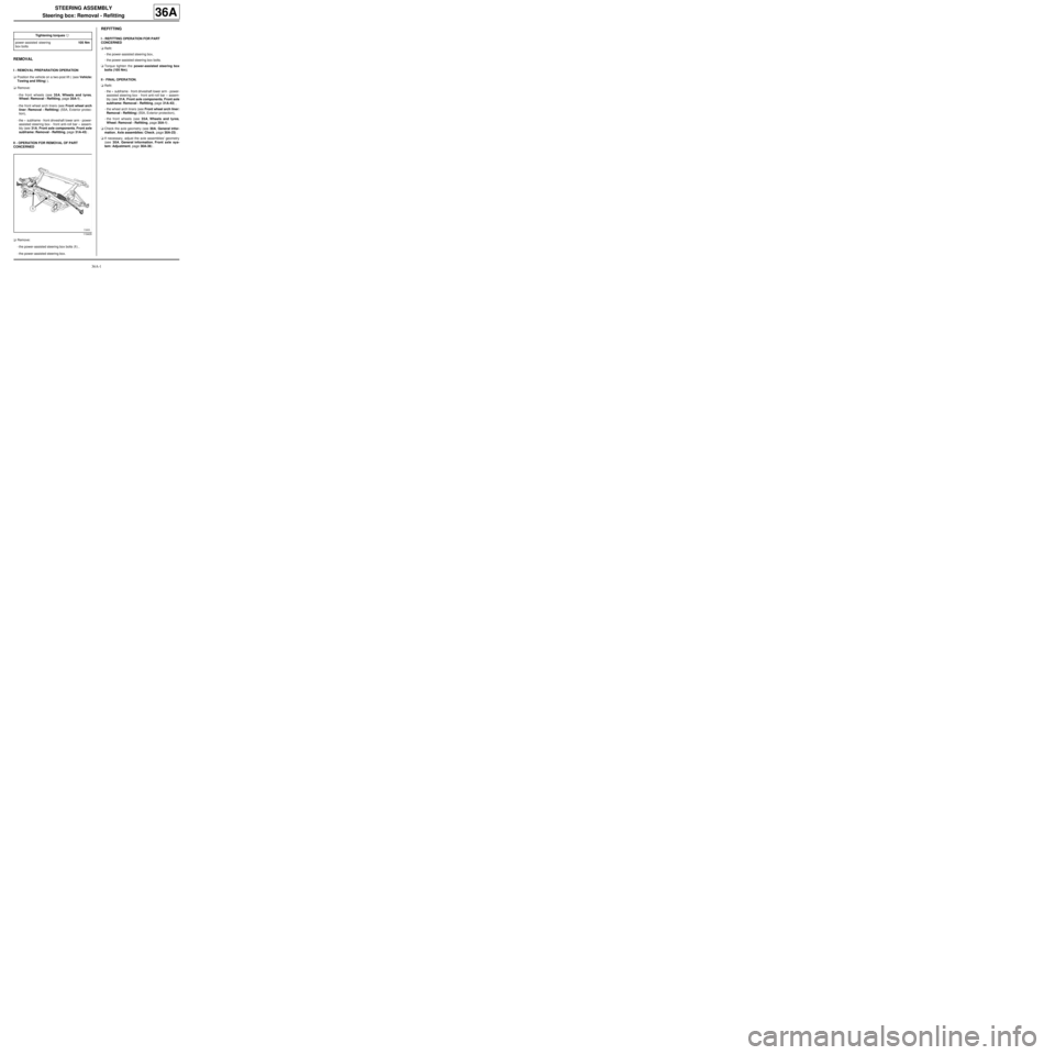
aRemove:
-the power-assisted steering box bolts (1) ,
-the power-assisted steering box.
REFITTING
I - REFITTING OPERATION FOR PART
CONCERNED
aRefit:
-the power-assisted steering box,
-the power-assisted steering box bolts.
aTorque tighten the power-assisted steering box
bolts (105 Nm).
II - FINAL OPERATION.
aRefit:
-the « subframe - front driveshaft lower arm - power-
assisted steering box - front anti-roll bar » assem-
bly (see 31A, Front axle components, Front axle
subframe: Removal - Refitting, page 31A-43) ,
-the wheel arch liners (see Front wheel arch liner:
Removal - Refitting) (55A, Exterior protection),
-the front wheels (see 35A, Wheels and tyres,
Wheel: Removal - Refitting, page 35A-1) .
aCheck the axle geometry (see 30A, General infor-
mation, Axle assemblies: Check, page 30A-23) .
aIf necessary, adjust the axle assemblies' geometry
(see 30A, General information, Front axle sys-
tem: Adjustment, page 30A-36) . Tightening torquesm
power-assisted steering
box bolts105 Nm
119405
Page 153 of 281
36A-2
STEERING ASSEMBLY
Track rod: Removal - Refitting
36A
REMOVAL
I - REMOVAL PREPARATION OPERATION
aPosition the vehicle on a two-post lift (see Vehicle:
Towing and lifting) (02A, Lifting equipment).
aRemove the front wheel (see 35A, Wheels and ty-
res, Wheel: Removal - Refitting, page 35A-1) .
II - OPERATION FOR REMOVAL OF PART
CONCERNED
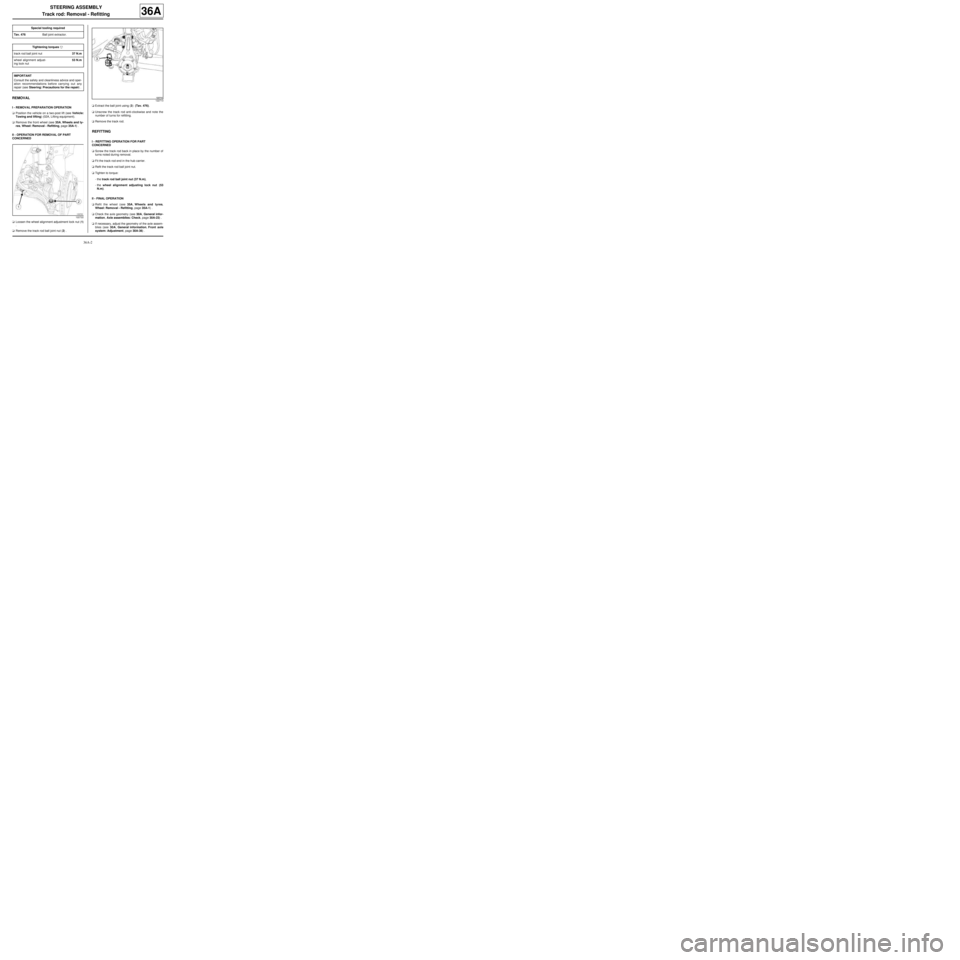
aLoosen the wheel alignment adjustment lock nut (1)
.
aRemove the track rod ball joint nut (2) .aExtract the ball joint using (3) (Tav. 476).
aUnscrew the track rod anti-clockwise and note the
number of turns for refitting.
aRemove the track rod.
REFITTING
I - REFITTING OPERATION FOR PART
CONCERNED
aScrew the track rod back in place by the number of
turns noted during removal.
aFit the track rod end in the hub carrier.
aRefit the track rod ball joint nut.
aTighten to torque:
-the track rod ball joint nut (37 N.m),
-the wheel alignment adjusting lock nut (53
N.m).
II - FINAL OPERATION
aRefit the wheel (see 35A, Wheels and tyres,
Wheel: Removal - Refitting, page 35A-1) .
aCheck the axle geometry (see 30A, General infor-
mation, Axle assemblies: Check, page 30A-23) .
aIf necessary, adjust the geometry of the axle assem-
blies (see 30A, General information, Front axle
system: Adjustment, page 30A-36) . Special tooling required
Tav. 476Ball joint extractor.
Tightening torquesm
track rod ball joint nut37 N.m
wheel alignment adjust-
ing lock nut53 N.m
IMPORTANT
Consult the safety and cleanliness advice and oper-
ation recommendations before carrying out any
repair (see Steering: Precautions for the repair) .
122722
122713
Page 154 of 281
36A-3
STEERING ASSEMBLY
Track rod: Removal - Refitting
36A