clutch RENAULT TWINGO RS 2009 2.G Chasiss Owner's Guide
[x] Cancel search | Manufacturer: RENAULT, Model Year: 2009, Model line: TWINGO RS, Model: RENAULT TWINGO RS 2009 2.GPages: 281
Page 238 of 281
37A-59
MECHANICAL COMPONENT CONTROLS
Clutch circuit: Bleed
JH3 or JR5
37A
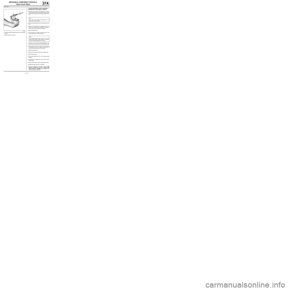
aPrefill the hydraulic tappet using the new syringe (by
gravity).
aRefit the part(s) concerned.V - BLEED PROCEDURE AFTER A REMOVING A
COMPONENT OF THE HYDRAULIC CIRCUIT.
aKeep the clutch pedal in the upper position using a
strap attached to the steering wheel to ensure conti-
nuity of the hydraulic circuit during the bleed opera-
tion.
aRemove the bleed plug from the clutch slave cylin-
der.
aConnect a transparent pipe of sufficient length to the
bleed hole (at least thirty centimetres) in order to
place it at the same height as the reservoir.
aOpen the bleed screw.
aFill the brake fluid master cylinder reservoir until
brake fluid flows out of the bleed screw.
aConnect a new syringe containing 60 ml of ap-
proved brake fluid to the end of the transparent pipe.
aSlowly inject the entire contents of the syringe into
the hydraulic clutch circuit without injecting any of
the air from the top section of the syringe.
aClose the bleed screw.
aRemove the transparent pipe from the bleed hole.
aRefit the bleed plug.
aTop up the brake fluid level in the master cylinder
reservoir.
aDisengage and engage the clutch quickly around
twenty times.
aCheck that the clutch system is operating correctly.
aRepeat the bleed operation if necessary.
aCheck the adjustment of the switch. (see 37A, Me-
chanical component controls, Clutch pedal
switch: Removal - Refitting, page 37A-52) (37A,
mechanical control elements).
141809
Note:
Take care not to disrupt the adjustment of the
clutch start of travel switch.
Note:
The transparent pipe must remain at the same
height as the master cylinder reser voir to prevent
air from enter ing inside the clutch circuit.
Page 239 of 281
37A-60
MECHANICAL COMPONENT CONTROLS
Clutch circuit: Bleed
JH3 or JR5
37A
VI - FINAL OPERATION
aRefit the engine undertray.
aRemove the vehicle from the two-post lift (see Vehi-
cle: Towing and lifting) (02A, Lifting equipment).
Page 240 of 281
37A-61
MECHANICAL COMPONENT CONTROLS
Clutch master cylinder: Removal - Refitting
JH3
37A
REMOVAL
I - REMOVAL PREPARATION OPERATION
aPosition the vehicle on a two-post lift (see Vehicle:
Towing and lifting) (MR 411, 02A, Lifting equip-
ment).
aRemove:
-the front wheel on the driver's side (see 35A,
Wheels and tyres, Wheel: Removal - Refitting,
page 35A-1) ,
-the front wheel arch liner on the driver's side (see
Front wheel arch liner: Removal - Refitting) (MR
412, 55A, Exterior protection).
aUse a syringe to empty the brake fluid reservoir.
II - OPERATION FOR REMOVAL OF PART
CONCERNED
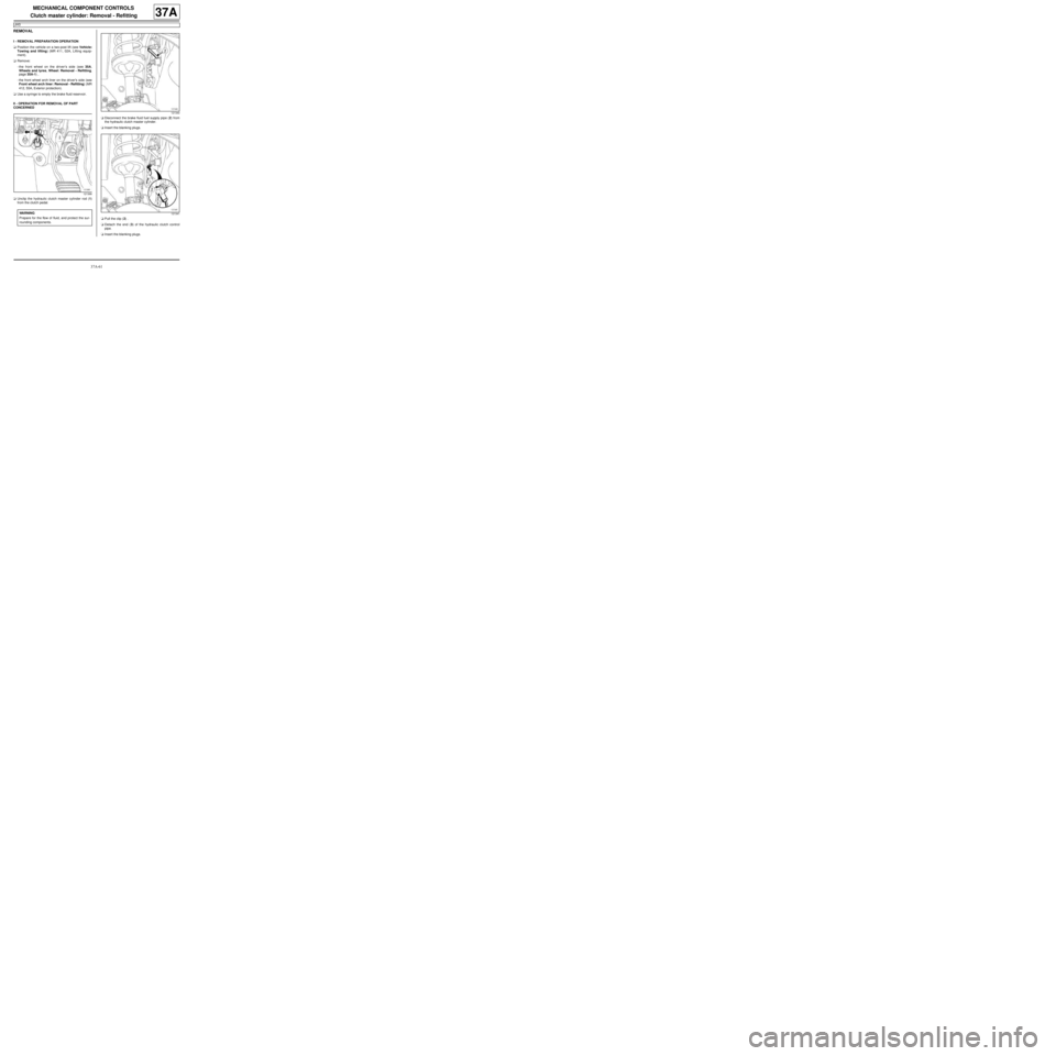
aUnclip the hydraulic clutch master cylinder rod (1)
from the clutch pedal.aDisconnect the brake fluid fuel supply pipe (2) from
the hydraulic clutch master cylinder.
aInsert the blanking plugs.
aPull the clip (2) .
aDetach the end (3) of the hydraulic clutch control
pipe.
aInsert the blanking plugs.
121366
WARNING
Prepare for the flow of fluid, and protect the sur-
rounding components.
121340
121341
Page 241 of 281
37A-62
MECHANICAL COMPONENT CONTROLS
Clutch master cylinder: Removal - Refitting
JH3
37A
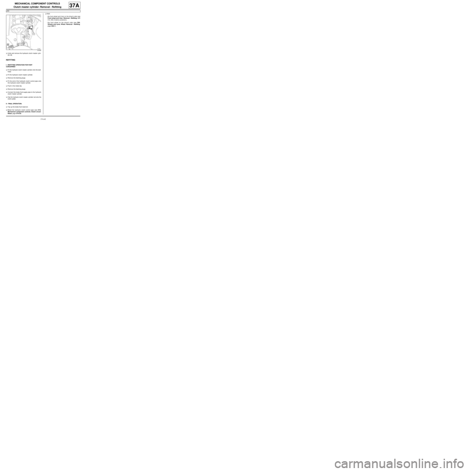
aUndo and remove the hydraulic clutch master cylin-
der (4) .
REFITTING
I - REFITTING OPERATION FOR PART
CONCERNED
aFit the hydraulic clutch master cylinder onto the bulk-
head.
aFit the hydraulic clutch master cylinder.
aRemove the blanking plugs.
aFit the end of the hydraulic clutch control pipe onto
the hydraulic clutch master cylinder.
aPush in the metal clip.
aRemove the blanking plugs.
aConnect the brake fluid supply pipe to the hydraulic
clutch master cylinder.
aClip the hydraulic clutch master cylinder rod onto the
clutch pedal.
II - FINAL OPERATION.
aTop up the brake fluid reservoir.
aBleed the hydraulic clutch control pipe (see 37A,
Mechanical component controls, Clutch circuit:
Bleed, page 37A-54) .aRefit:
-the front wheel arch liner on the driver's side (see
Front wheel arch liner: Removal - Refitting) (MR
412, 55A, Exterior protection),
-the front wheel on the driver's side (see 35A,
Wheels and tyres, Wheel: Removal - Refitting,
page 35A-1) .
121342
Page 242 of 281

37A-63
MECHANICAL COMPONENT CONTROLS
Clutch circuit: Removal - Refitting
JH3
37A
REMOVAL
I - REMOVAL PREPARATION OPERATION
aPosition the vehicle on a two-post lift (see Vehicle:
Towing and lifting) (MR 411, 02A, Lifting equip-
ment).
aRemove:
-the front wheel on the driver's side (see 35A,
Wheels and tyres, Wheel: Removal - Refitting,
page 35A-1) ,
-the front wheel arch liner on the driver's side (see
Front wheel arch liner: Removal - Refitting) (MR
412, 55A, Exterior protection),
-the battery (see Battery: Removal - Refitting)
(MR 411, 80A, Battery),
-the battery tray (see Battery tray: Removal - Re-
fitting) (MR 411, 80A, Battery).
aEmpty the brake fluid reservoir with a syringe.
II - OPERATION FOR REMOVAL OF PART
CONCERNED
aPress and hold the clip (1) .
aPull out the hydraulic clutch control pipe by one
notch.aPress and hold the clip (1) again.
aPull the hydraulic clutch control pipe out another
notch and collect the fluid in a container.
aDepress the clutch pedal to empty the hydraulic
clutch control circuit.
aDetach the pipe at (2) and (3) .
121354
WARNING
Prepare for the flow of fluid, and protect the sur-
rounding components.
121118
121114
Page 243 of 281
37A-64
MECHANICAL COMPONENT CONTROLS
Clutch circuit: Removal - Refitting
JH3
37A
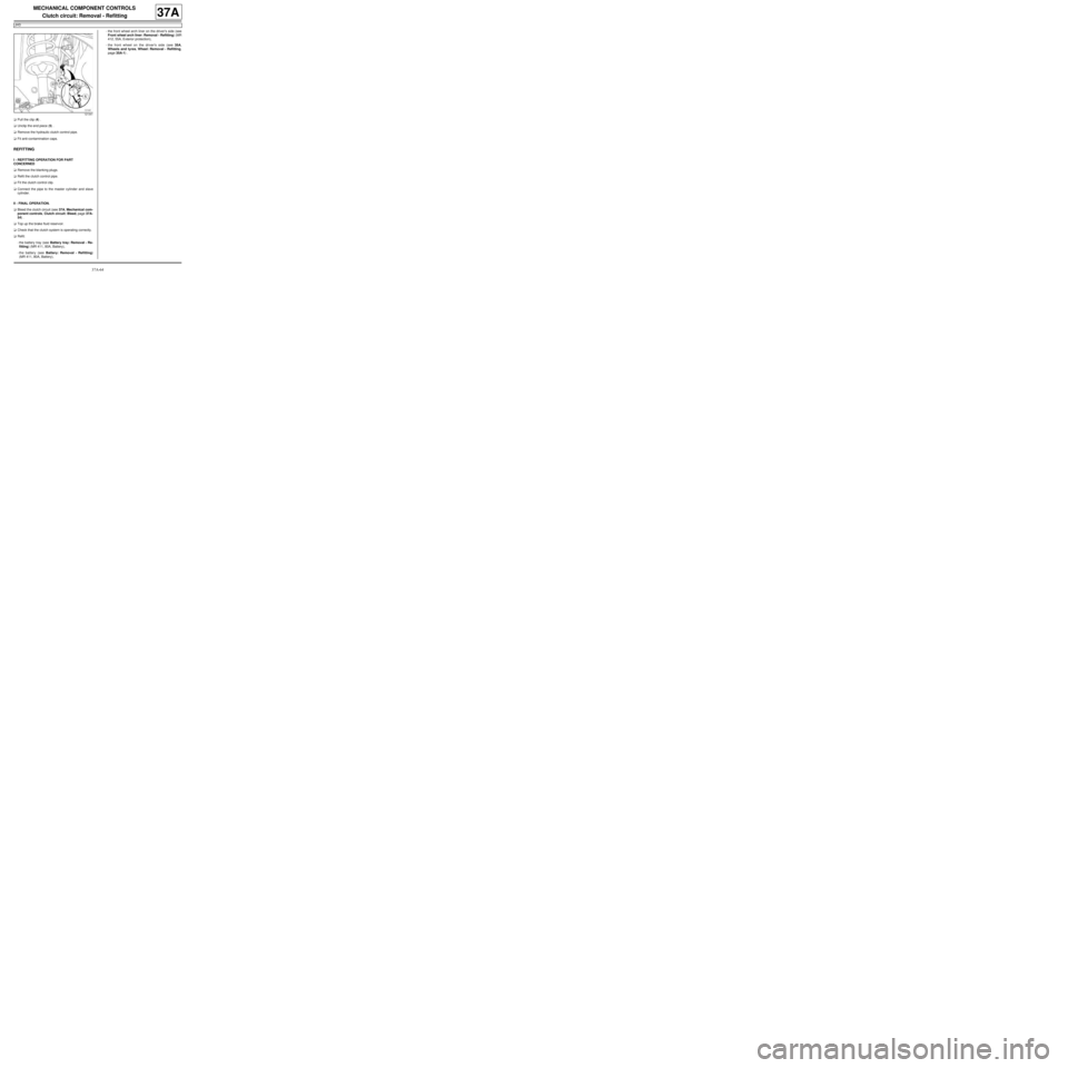
aPull the clip (4) .
aUnclip the end piece (5) .
aRemove the hydraulic clutch control pipe.
aFit anti-contamination caps.
REFITTING
I - REFITTING OPERATION FOR PART
CONCERNED
aRemove the blanking plugs.
aRefit the clutch control pipe.
aFit the clutch control clip.
aConnect the pipe to the master cylinder and slave
cylinder.
II - FINAL OPERATION.
aBleed the clutch circuit (see 37A, Mechanical com-
ponent controls, Clutch circuit: Bleed, page 37A-
54) .
aTop up the brake fluid reservoir.
aCheck that the clutch system is operating correctly.
aRefit:
-the battery tray (see Battery tray: Removal - Re-
fitting) (MR 411, 80A, Battery),
-the battery (see Battery: Removal - Refitting)
(MR 411, 80A, Battery),-the front wheel arch liner on the driver's side (see
Front wheel arch liner: Removal - Refitting) (MR
412, 55A, Exterior protection),
-the front wheel on the driver's side (see 35A,
Wheels and tyres, Wheel: Removal - Refitting,
page 35A-1) .
121341