lock RENAULT TWINGO RS 2009 2.G Chasiss Service Manual
[x] Cancel search | Manufacturer: RENAULT, Model Year: 2009, Model line: TWINGO RS, Model: RENAULT TWINGO RS 2009 2.GPages: 281
Page 223 of 281
37A-44
MECHANICAL COMPONENT CONTROLS
Brake pedal switch: Removal - Refitting
37A
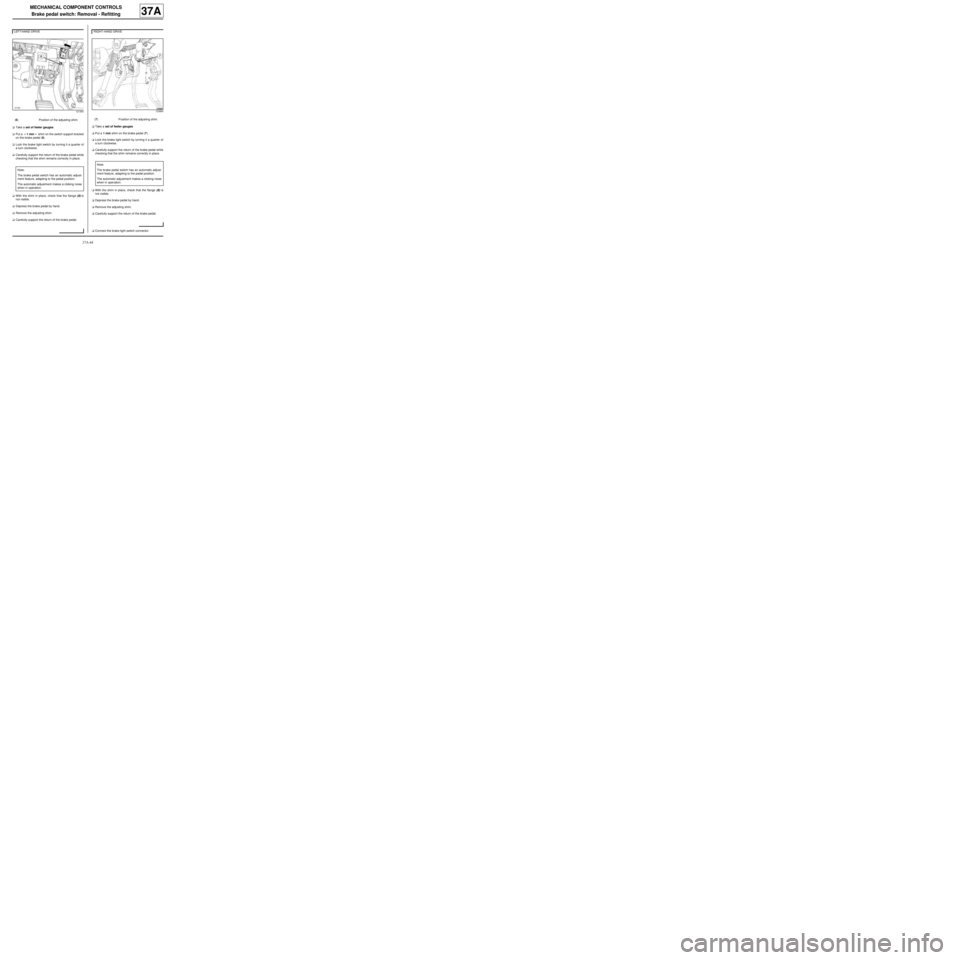
aTake a set of feeler gauges
aPut a « 1 mm » shim on the switch support bracket
on the brake pedal (6) .
aLock the brake light switch by turning it a quarter of
a turn clockwise.
aCarefully support the return of the brake pedal while
checking that the shim remains correctly in place.
aWith the shim in place, check that the flange (8) is
not visible.
aDepress the brake pedal by hand.
aRemove the adjusting shim.
aCarefully support the return of the brake pedal.aTake a set of feeler gauges
aPut a 1 mm shim on the brake pedal (7) .
aLock the brake light switch by turning it a quarter of
a turn clockwise.
aCarefully support the return of the brake pedal while
checking that the shim remains correctly in place.
aWith the shim in place, check that the flange (8) is
not visible.
aDepress the brake pedal by hand.
aRemove the adjusting shim.
aCarefully support the return of the brake pedal.
aConnect the brake light switch connector. LEFT-HAND DRIVE
121350
(6) Position of the adjusting shim.
Note:
The brake pedal switch has an automatic adjust-
ment feature, adapting to the pedal position.
The automatic adjustment makes a clicking noise
when in operation.
RIGHT-HAND DRIVE
123860
(7) Position of the adjusting shim.
Note:
The br ake pedal switch has an automatic adjust-
ment feature, adapting to the pedal position.
The automatic adjustment makes a clicking noise
when in oper ation.
Page 231 of 281
37A-52
MECHANICAL COMPONENT CONTROLS
Clutch pedal switch: Removal - Refitting
CRUISE CONTROL, and 5-SPEED MANUAL GEARBOX
37A
REMOVAL
I - REMOVAL PREPARATION OPERATION
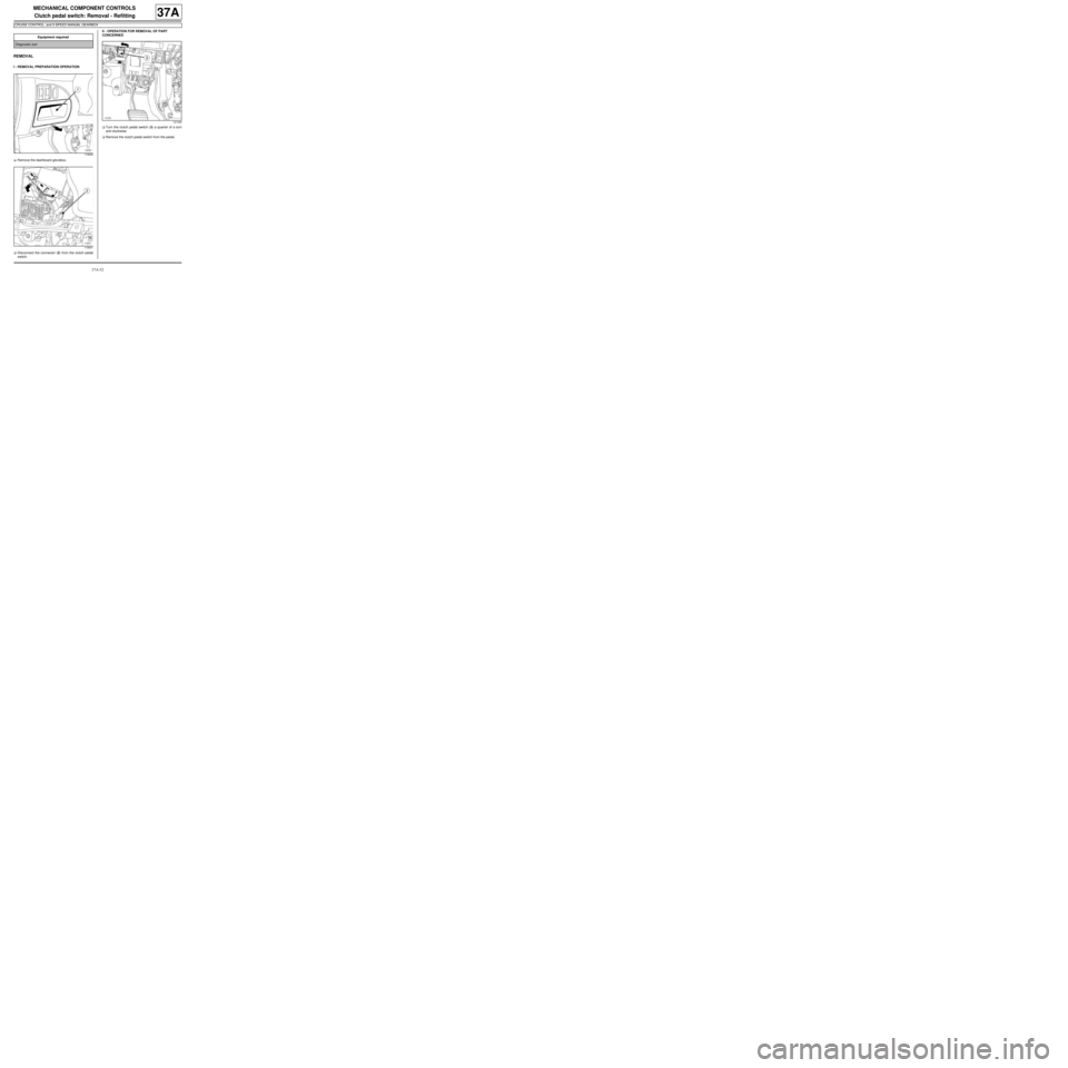
aRemove the dashboard glovebox.
aDisconnect the connector (2) from the clutch pedal
switch.II - OPERATION FOR REMOVAL OF PART
CONCERNED
aTurn the clutch pedal switch (3) a quarter of a turn
anti-clockwise
aRemove the clutch pedal switch from the pedal. Equipment required
Diagnostic tool
119506
119507
121349
Page 232 of 281
37A-53
MECHANICAL COMPONENT CONTROLS
Clutch pedal switch: Removal - Refitting
CRUISE CONTROL, and 5-SPEED MANUAL GEARBOX
37A
REFITTING
I - REFITTING PREPARATIONS OPERATION
a
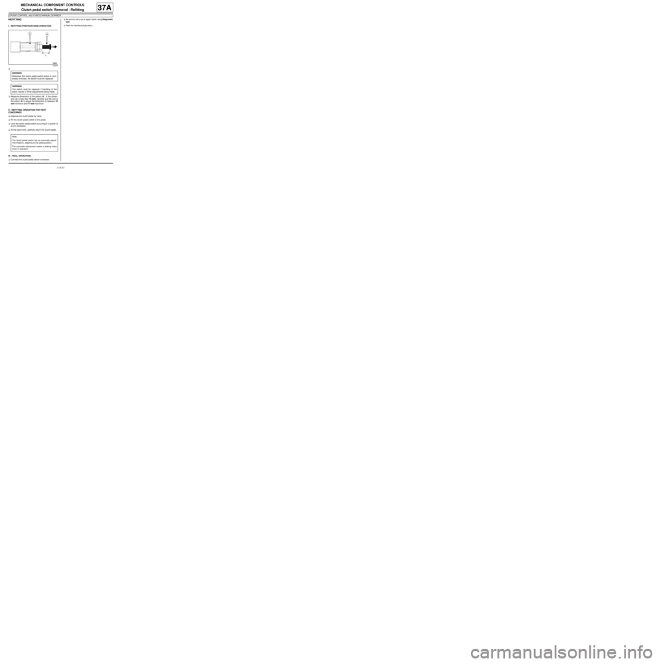
aMeasure dimension of the piston (4) . If the dimen-
sion (x) is less than 15 mm, carefully pull the end of
the piston (4) to adjust the dimension to between 15
mm minimum and 17 mm maximum.
II - REFITTING OPERATION FOR PART
CONCERNED
aDepress the clutch pedal by hand.
aFit the clutch pedal switch to the pedal.
aLock the clutch pedal switch by turning it a quarter of
a turn clockwise.
aAt the same time, carefully return the clutch pedal.
III - FINAL OPERATION.
aConnect the clutch pedal switch connector.aBe sure to carry out a repair check using Diagnostic
tool.
aRefit the dashboard glovebox.
108436
WARNING
Whenever the clutch pedal switch piston is com-
pletely removed, the switch must be replaced.
WARNING
The switch must be replaced if handling of the
piston results in three adjustments being made.
Note:
The clutch pedal switch has an automatic adjust-
ment feature, adapting to the pedal position.
The automatic adjustment makes a clicking noise
when in operation.
Page 250 of 281
37A-71
MECHANICAL COMPONENT CONTROLS
Gear control unit: Adjustment
JB1
37A
ADJUSTMENT
I - ADJUSTMENT PREPARATION STAGE
aPosition the vehicle on a two-post lift (see Vehicle:
Towing and lifting) (MR 411, 02A, Lifting equip-
ment).
aEngage first gear.
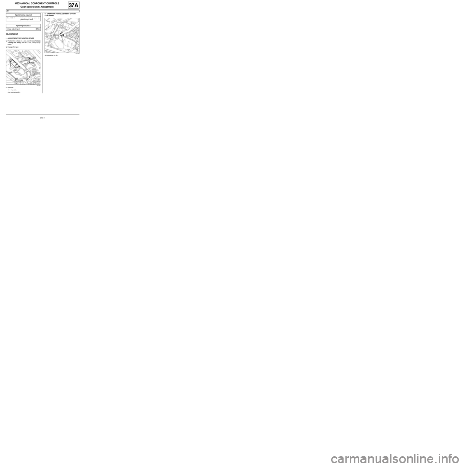
aRemove:
-the clips (1) ,
-the heat shield (2) .II - OPERATION FOR ADJUSTMENT OF PART
CONCERNED
aUnlock the nut (3) . Special tooling required
Bvi. 1133-011st gear locking shim for
gearbox input lever.
Tightening torquesm
linkage adjusting nut30 Nm
121327
121339
Page 260 of 281
38C-1
ANTI-LOCK BRAKING SYSTEM
Hydraulic brake unit: List and location of components38C
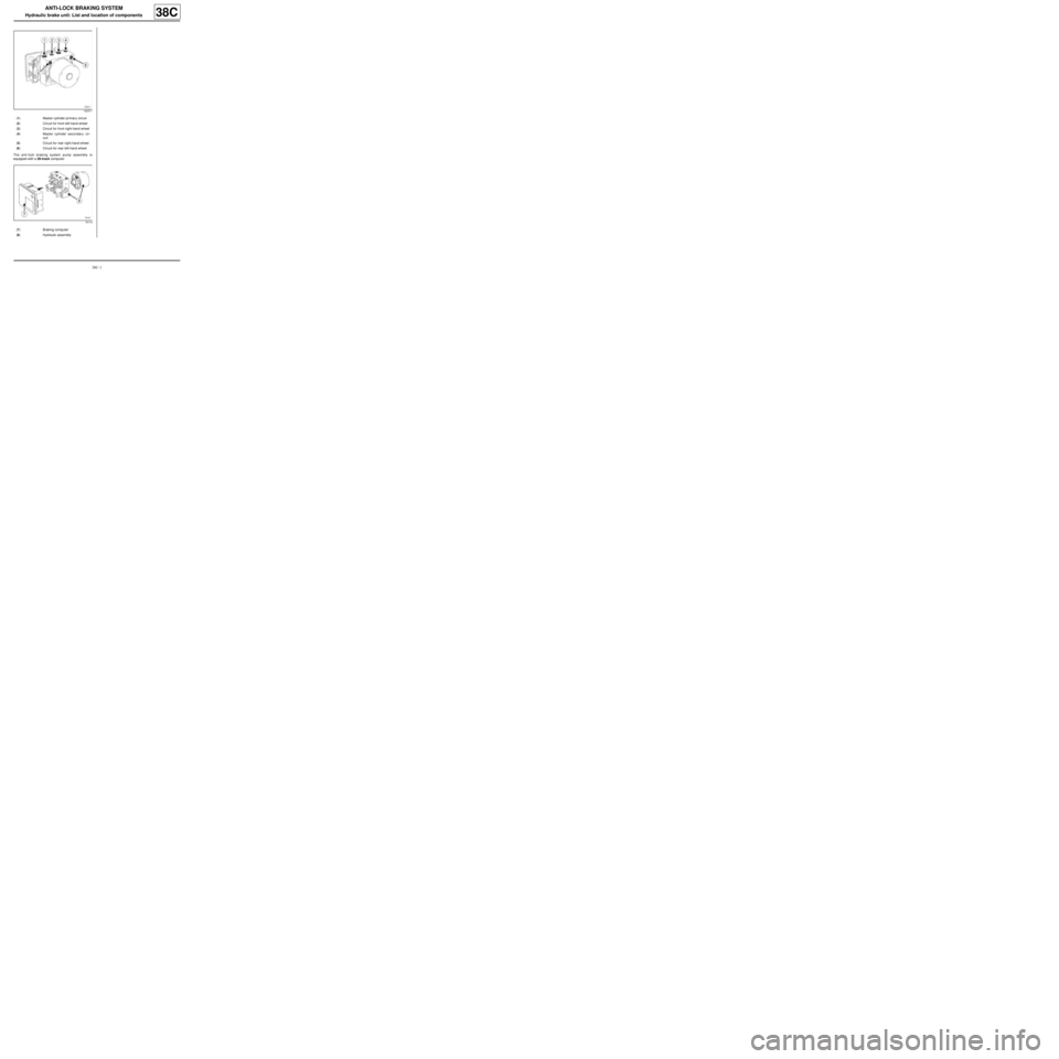
The anti-lock braking system pump assembly is
equipped with a 26-track computer.
102311
(1) Master cylinder pr imar y circuit
(2) Circuit for front left-hand wheel
(3) Circuit for front right-hand wheel
(4) Master cylinder secondary cir-
cuit
(5) Circuit for rear right-hand wheel
(6) Circuit for rear left-hand wheel
19113
(7) Braking computer
(8) Hydraulic assembly
Page 261 of 281
38C-2
ANTI-LOCK BRAKING SYSTEM
Hydraulic brake unit: Removal - Refitting
K9K, and LEFT-HAND DRIVE
38C
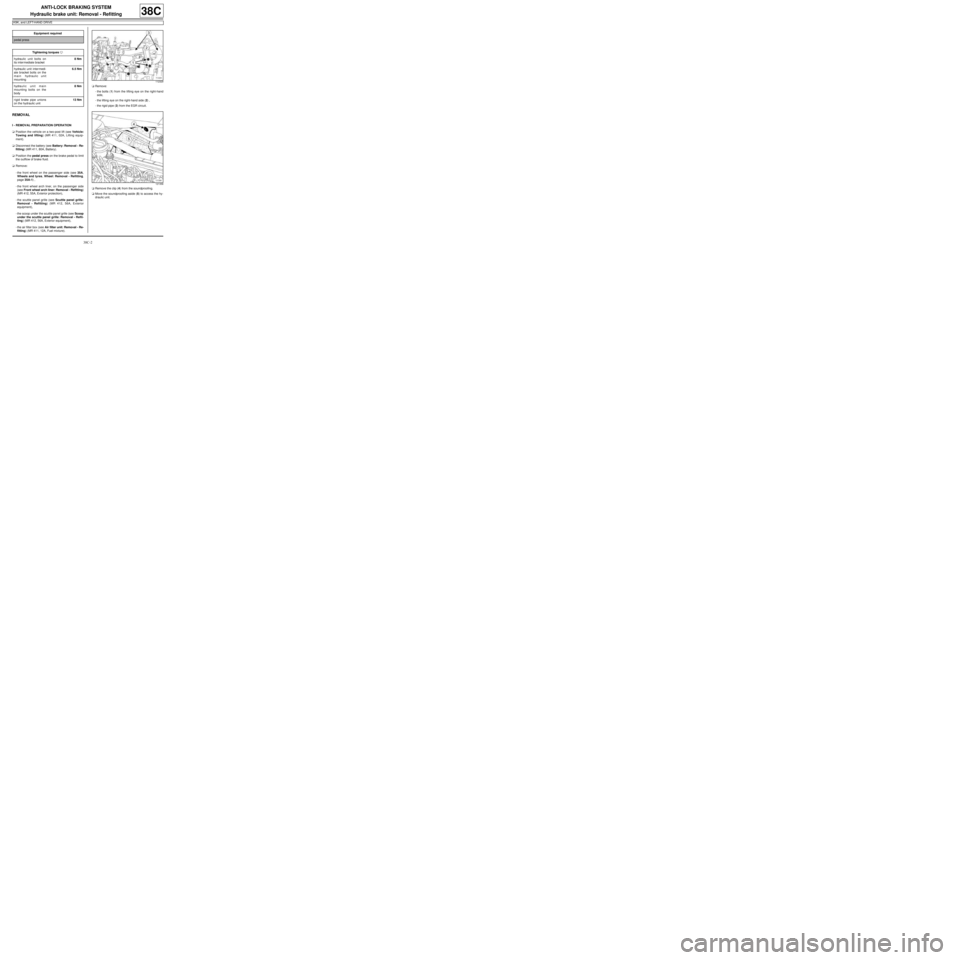
REMOVAL
I - REMOVAL PREPARATION OPERATION
aPosition the vehicle on a two-post lift (see Vehicle:
Towing and lifting) (MR 411, 02A, Lifting equip-
ment).
aDisconnect the battery (see Battery: Removal - Re-
fitting) (MR 411, 80A, Battery).
aPosition the pedal press on the brake pedal to limit
the outflow of brake fluid.
aRemove:
-the front wheel on the passenger side (see 35A,
Wheels and tyres, Wheel: Removal - Refitting,
page 35A-1) ,
-the front wheel arch liner, on the passenger side
(see Front wheel arch liner: Removal - Refitting)
(MR 412, 55A, Exterior protection),
-the scuttle panel grille (see Scuttle panel grille:
Removal - Refitting) (MR 412, 56A, Exterior
equipment),
-the scoop under the scuttle panel grille (see Scoop
under the scuttle panel grille: Removal - Refit-
ting) (MR 412, 56A, Exterior equipment),
-the air filter box (see Air filter unit: Removal - Re-
fitting) (MR 411, 12A, Fuel mixture).aRemove:
-the bolts (1) from the lifting eye on the right-hand
side,
-the lifting eye on the right-hand side (2) ,
-the rigid pipe (3) from the EGR circuit.
aRemove the clip (4) from the soundproofing.
aMove the soundproofing aside (5) to access the hy-
draulic unit. Equipment required
pedal press
Tightening torquesm
hydraulic unit bolts on
its inter mediate bracket8 Nm
hydraulic unit inter medi-
ate bracket bolts on the
main hydraulic unit
mounting6.5 Nm
hydraulic unit main
mounting bolts on the
body8 Nm
rigid brake pipe unions
on the hydraulic unit13 Nm
112329
121358
Page 262 of 281
38C-3
ANTI-LOCK BRAKING SYSTEM
Hydraulic brake unit: Removal - Refitting
K9K, and LEFT-HAND DRIVE
38C
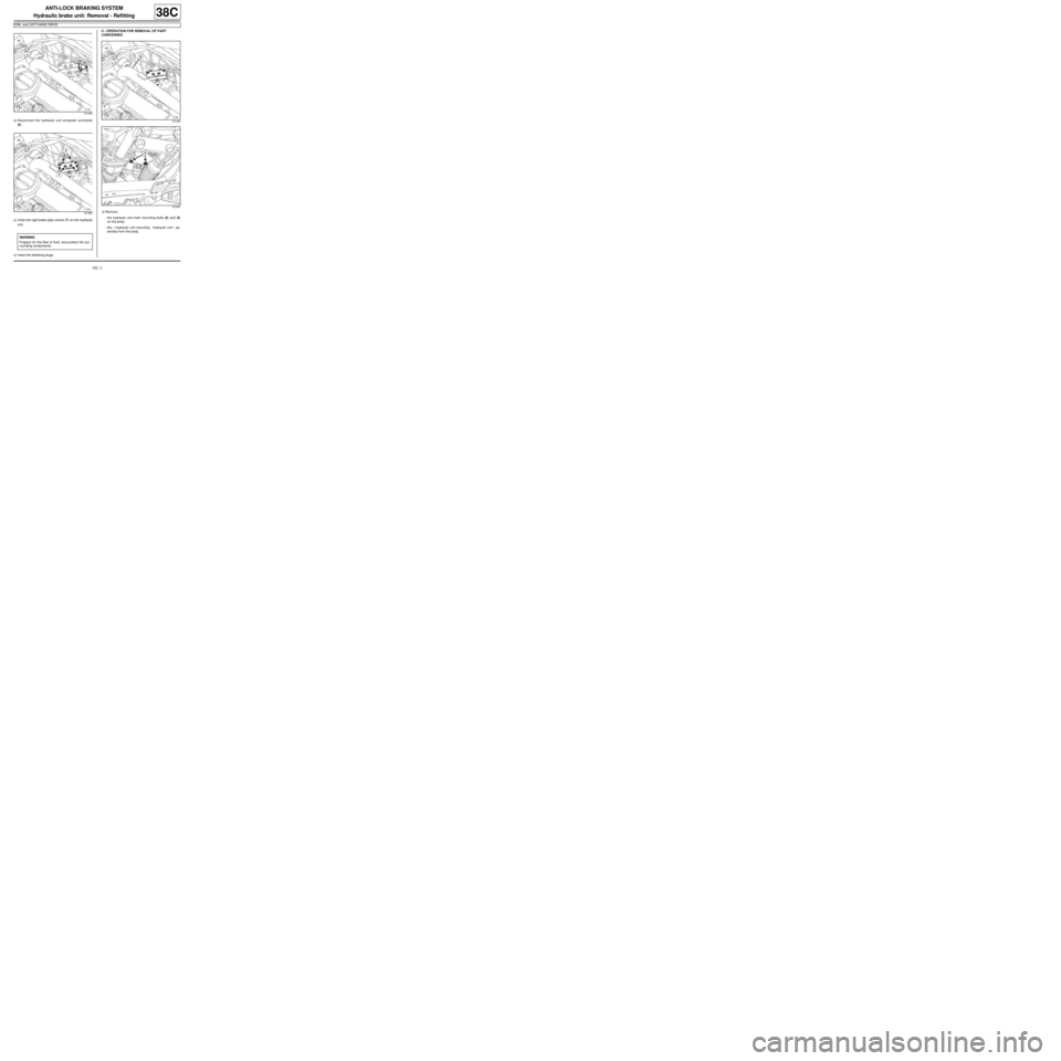
aDisconnect the hydraulic unit computer connector
(6) .
aUndo the rigid brake pipe unions (7) on the hydraulic
unit.
aInsert the blanking plugs.II - OPERATION FOR REMOVAL OF PART
CONCERNED
aRemove:
-the hydraulic unit main mounting bolts (8) and (9)
on the body,
-the « hydraulic unit mounting - hydraulic unit » as-
sembly from the body.
121359
121360
WARNING
Prepare for the flow of fluid, and protect the sur-
rounding components.
121360
121361
Page 263 of 281
38C-4
ANTI-LOCK BRAKING SYSTEM
Hydraulic brake unit: Removal - Refitting
K9K, and LEFT-HAND DRIVE
38C
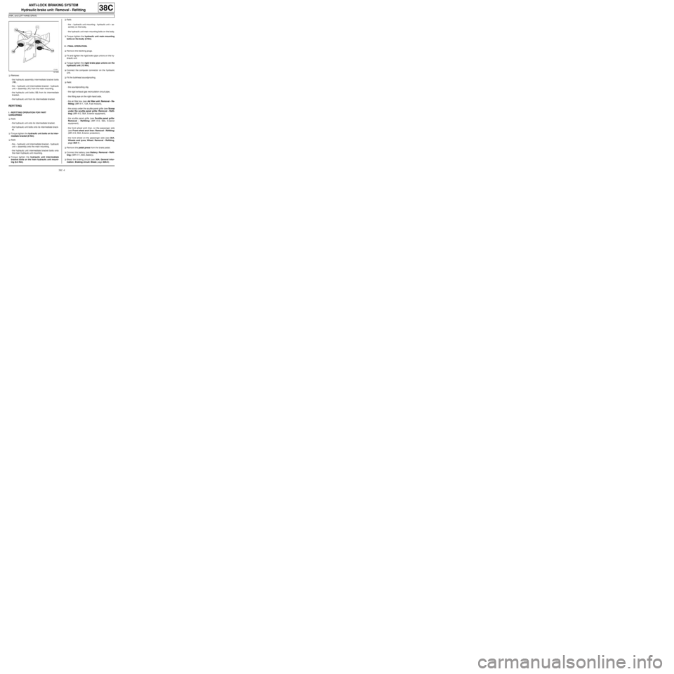
aRemove:
-the hydraulic assembly intermediate bracket bolts
(10) ,
-the « hydraulic unit intermediate bracket - hydraulic
unit » assembly (11) from the main mounting,
-the hydraulic unit bolts (12) from its intermediate
bracket,
-the hydraulic unit from its intermediate bracket.
REFITTING
I - REFITTING OPERATION FOR PART
CONCERNED
aRefit:
-the hydraulic unit onto its intermediate bracket,
-the hydraulic unit bolts onto its intermediate brack-
et.
aTorque tighten the hydraulic unit bolts on its inter-
mediate bracket (8 Nm).
aRefit:
-the « hydraulic unit intermediate bracket - hydraulic
unit » assembly onto the main mounting,
-the hydraulic unit intermediate bracket bolts onto
the main hydraulic unit mounting.
aTorque tighten the hydraulic unit intermediate
bracket bolts on the main hydraulic unit mount-
ing (6.5 Nm).aRefit:
-the « hydraulic unit mounting - hydraulic unit » as-
sembly on the body,
-the hydraulic unit main mounting bolts on the body.
aTorque tighten the hydraulic unit main mounting
bolts on the body (8 Nm).
II - FINAL OPERATION.
aRemove the blanking plugs.
aFit and tighten the rigid brake pipe unions on the hy-
draulic unit.
aTorque tighten the rigid brake pipe unions on the
hydraulic unit (13 Nm).
aConnect the computer connector on the hydraulic
unit.
aFit the bulkhead soundproofing.
aRefit:
-the soundproofing clip,
-the rigid exhaust gas recirculation circuit pipe,
-the lifting eye on the right-hand side,
-the air filter box (see Air filter unit: Removal - Re-
fitting) (MR 411, 12A, Fuel mixture),
-the scoop under the scuttle panel grille (see Scoop
under the scuttle panel grille: Removal - Refit-
ting) (MR 412, 56A, Exterior equipment),
-the scuttle panel grille (see Scuttle panel grille:
Removal - Refitting) (MR 412, 56A, Exterior
equipment),
-the front wheel arch liner, on the passenger side
(see Front wheel arch liner: Removal - Refitting)
(MR 412, 55A, Exterior protection),
-the front wheel on the passenger side (see 35A,
Wheels and tyres, Wheel: Removal - Refitting,
page 35A-1) .
aRemove the pedal press from the brake pedal.
aConnect the battery (see Battery: Removal - Refit-
ting) (MR 411, 80A, Battery).
aBleed the braking circuit (see 30A, General infor-
mation, Braking circuit: Bleed, page 30A-4) .
121456
Page 264 of 281
38C-5
ANTI-LOCK BRAKING SYSTEM
Hydraulic brake unit: Removal - Refitting
D4F or D7F, and LEFT-HAND DRIVE
38C
REMOVAL
I - REMOVAL PREPARATION OPERATION
aPosition the vehicle on a two-post lift (see Vehicle:
Towing and lifting) (MR 411, 02A, Lifting equip-
ment).
aDisconnect the battery (see Battery: Removal - Re-
fitting) (MR 411, 80A, Battery).
aPosition the pedal press on the brake pedal to limit
the outflow of brake fluid.
aRemove:
-the front wheel on the passenger side (see 35A,
Wheels and tyres, Wheel: Removal - Refitting,
page 35A-1) ,
-the front wheel arch liner, on the passenger side
(see Front wheel arch liner: Removal - Refitting)
(MR 412, 55A, Exterior protection),
-the ignition coil (see Coils: Removal - Refitting)
(MR 411, 17A, Ignition),
-the fuel vapour recirculation circuit solenoid valve
(see Fuel vapour absorber: Removal - Refitting)
(MR 411, 14A, Emission control),
-the air filter box (see Air filter unit: Removal - Re-
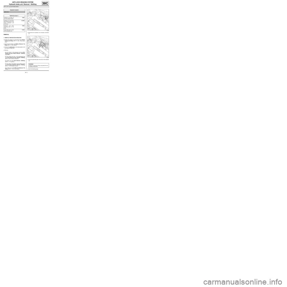
fitting) (MR 411, 12A, Fuel mixture).aDisconnect the hydraulic unit computer connector
(1) .
aUndo the rigid brake pipe unions (2) on the hydraulic
unit.
aInsert the blanking plugs. Equipment required
pedal press
Tightening torquesm
hydraulic unit bolts on
its inter mediate bracket8 Nm
hydraulic unit inter medi-
ate bracket bolts on the
main hydraulic unit
mounting6.5 Nm
hydraulic unit main
mounting bolts on the
body8 Nm
rigid brake pipe unions
on the hydraulic unit13 Nm
121359
121360
WARNING
Prepare for the flow of fluid, and protect the sur-
rounding components.
Page 265 of 281
38C-6
ANTI-LOCK BRAKING SYSTEM
Hydraulic brake unit: Removal - Refitting
D4F or D7F, and LEFT-HAND DRIVE
38C
II - OPERATION FOR REMOVAL OF PART
CONCERNED
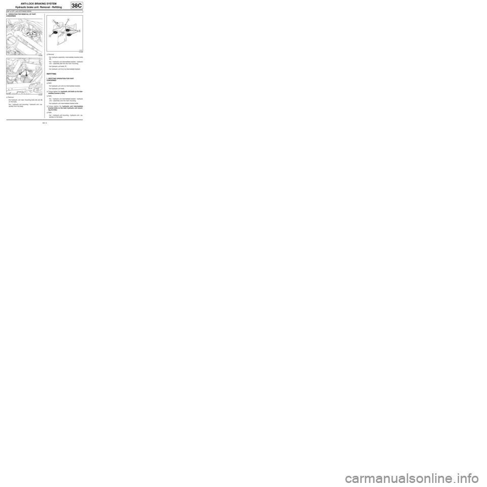
aRemove:
-the hydraulic unit main mounting bolts (3) and (4)
on the body,
-the « hydraulic unit mounting - hydraulic unit » as-
sembly from the body.aRemove:
-the hydraulic assembly intermediate bracket bolts
(5) ,
-the « hydraulic unit intermediate bracket - hydraulic
unit » assembly (6) from the main mounting,
-the hydraulic unit bolts (7) ,
-the hydraulic unit from its intermediate bracket.
REFITTING
I - REFITTING OPERATION FOR PART
CONCERNED
aRefit:
-the hydraulic unit onto its intermediate bracket,
-the hydraulic unit bolts.
aTorque tighten the hydraulic unit bolts on its inter-
mediate bracket ( 8 Nm).
aRefit:
-the « hydraulic unit intermediate bracket - hydraulic
unit » assembly onto the main mounting,
-the hydraulic unit intermediate bracket bolts.
aTorque tighten the hydraulic unit intermediate
bracket bolts on the main hydraulic unit mount-
ing ( 6.5 Nm).
aRefit:
-the « hydraulic unit mounting - hydraulic unit » as-
sembly on the body,
121360
121361
121456