lock RENAULT TWINGO RS 2009 2.G Chasiss User Guide
[x] Cancel search | Manufacturer: RENAULT, Model Year: 2009, Model line: TWINGO RS, Model: RENAULT TWINGO RS 2009 2.GPages: 281
Page 58 of 281
31A-15
FRONT AXLE COMPONENTS
Front brake calliper mounting: Removal - Refitting
EQ UIPMENT LEVEL EA0 or EQUIPMENT LEVEL EA1 or EQUIPMENT LEVEL EA3 or EQUIPMENT LEVEL EA5
or EQUIPMENT LEVEL EAG or EQUIPMENT LEVEL EZ2 or EQUIPMENT LEVEL EZ4
31A
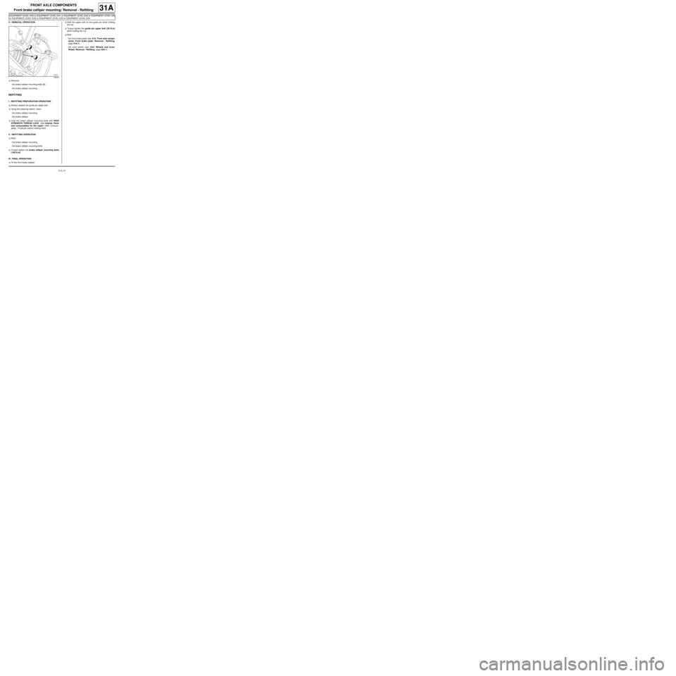
II - REMOVAL OPERATION
aRemove:
-the brake calliper mounting bolts (3) ,
-the brake calliper mounting.
REFITTING
I - REFITTING PREPARATION OPERATION
aAlways replace the guide pin upper bolt.
aUsing the cleaning station, clean:
-the brake calliper mounting,
-the brake calliper.
aCoat the brake calliper mounting bolts with HIGH
STRENGTH THREAD LOCK (see Vehicle: Parts
and consumables for the repair) (04B, Consum-
ables - Products) before refitting them.
II - REFITTING OPERATION
aRefit:
-the brake calliper mounting,
-the brake calliper mounting bolts.
aTorque tighten the brake calliper mounting bolts
(100 N.m).
III - FINAL OPERATION
aFit the front brake calliper.aRefit the upper bolt on the guide pin while holding
the nut.
aTorque tighten the guide pin upper bolt (29 N.m)
while holding the nut.
aRefit:
-the front brake pads (see 31A, Front axle compo-
nents, Front brake pads: Removal - Refitting,
page 31A-1) ,
-the front wheel (see 35A, Wheels and tyres,
Wheel: Removal - Refitting, page 35A-1) .
119219
Page 66 of 281
31A-23
FRONT AXLE COMPONENTS
Front driveshaft hub carrier: Removal - Refitting
31A
REMOVAL
I - REMOVAL PREPARATION OPERATION
aPosition the vehicle on a two-post lift (see Vehicle:
Towing and lifting) (MR 411, 02A, Lifting equip-
ment).
aRemove:
-the front wheel on the side in question (see 35A,
Wheels and tyres, Wheel: Removal - Refitting,
page 35A-1) ,
-the front brake pads of the side in question (see
31A, Front axle components, Front brake pads:
Removal - Refitting, page 31A-1) ,
aRemove:
-the front brake calliper mounting (see 31A, Front
axle components, Front brake calliper mount-
ing: Removal - Refitting, page 31A-14) ,
-the front brake disc (see 31A, Front axle compo-
nents, Front brake disc: Removal - Refitting,
page 31A-19) ,
-the front wheel speed sensor on the hub carrier
(see 38C, Anti-lock braking system, Front wheel
speed sensor: Removal - Refitting, page 38C-
15) .II - OPERATION FOR REMOVAL OF PART
CONCERNED
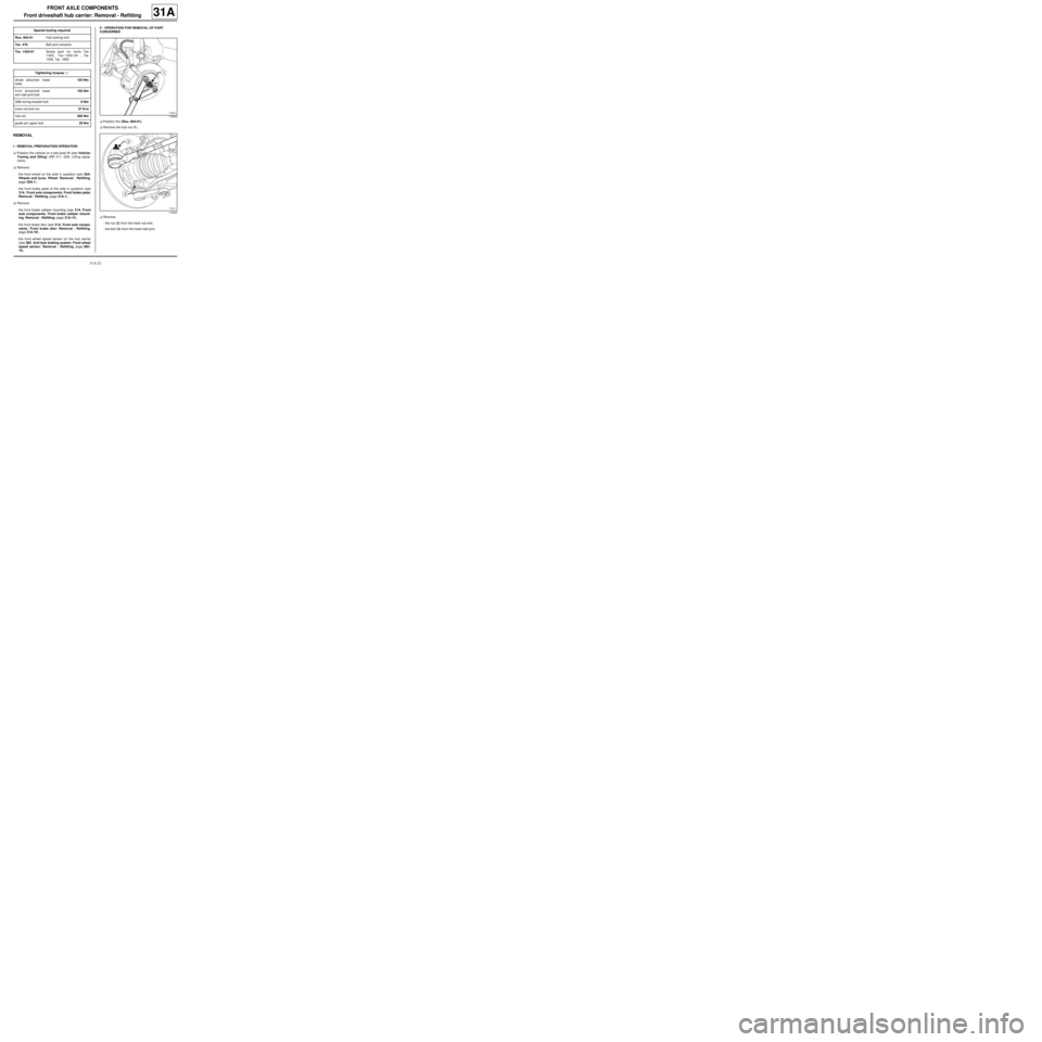
aPosition the (Rou. 604-01).
aRemove the hub nut (1) .
aRemove:
-the nut (2) from the track rod end,
-the bolt (3) from the lower ball joint. Special tooling required
Rou. 604-01Hub locking tool.
Tav. 476Ball joint extractor.
Tav. 1420-01Screw jack for tools Tav.
1420, Tav.1050-04 , Tar.
1454, Tar. 1850.
Tightening torquesm
shock absorber lower
bolts105 Nm
front driveshaft lower
arm ball joint bolt105 Nm
ABS wiring bracket bolt8 Nm
track rod end nut37 N.m
hub nut280 Nm
guide pin upper bolt29 Nm
119543
119222
Page 123 of 281
33A-25
REAR AXLE COMPONENTS
Shock absorber: Removal - Refitting
33A
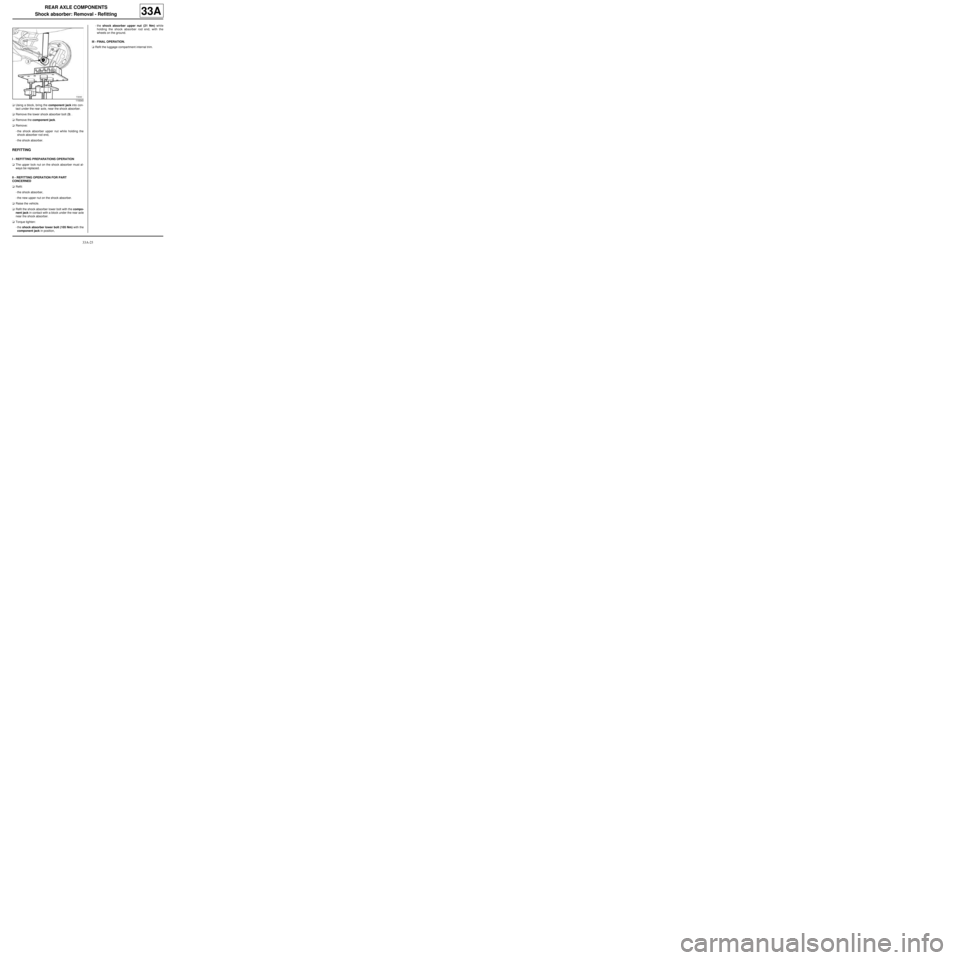
aUsing a block, bring the component jack into con-
tact under the rear axle, near the shock absorber.
aRemove the lower shock absorber bolt (3) .
aRemove the component jack.
aRemove:
-the shock absorber upper nut while holding the
shock absorber rod end,
-the shock absorber.
REFITTING
I - REFITTING PREPARATIONS OPERATION
aThe upper lock nut on the shock absorber must al-
ways be replaced.
II - REFITTING OPERATION FOR PART
CONCERNED
aRefit:
-the shock absorber,
-the new upper nut on the shock absorber.
aRaise the vehicle.
aRefit the shock absorber lower bolt with the compo-
nent jack in contact with a block under the rear axle
near the shock absorber.
aTorque tighten:
-the shock absorber lower bolt (105 Nm) with the
component jack in position,-the shock absorber upper nut (21 Nm) while
holding the shock absorber rod end, with the
wheels on the ground.
III - FINAL OPERATION.
aRefit the luggage compartment internal trim.
119340
Page 125 of 281
33A-27
REAR AXLE COMPONENTS
Shock absorber: Removal - Refitting
G44
33A
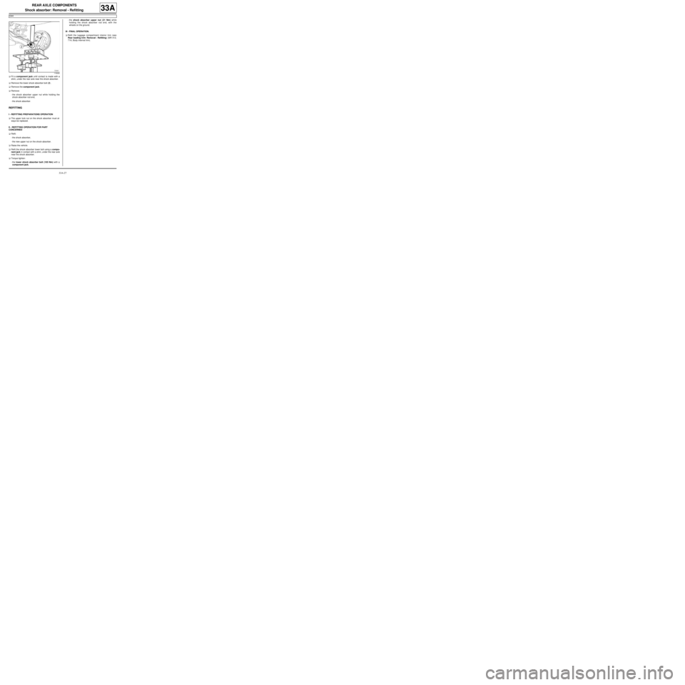
aFit a component jack until contact is made with a
shim, under the rear axle near the shock absorber.
aRemove the lower shock absorber bolt (2) .
aRemove the component jack.
aRemove:
-the shock absorber upper nut while holding the
shock absorber rod end,
-the shock absorber.
REFITTING
I - REFITTING PREPARATIONS OPERATION
aThe upper lock nut on the shock absorber must al-
ways be replaced.
II - REFITTING OPERATION FOR PART
CONCERNED
aRefit:
-the shock absorber,
-the new upper nut on the shock absorber.
aRaise the vehicle.
aRefit the shock absorber lower bolt using a compo-
nent jack in contact with a shim, under the rear axle
near the shock absorber.
aTorque tighten:
-the lower shock absorber bolt (105 Nm) with a
component jack,-the shock absorber upper nut (21 Nm) while
holding the shock absorber rod end, with the
wheels on the ground.
III - FINAL OPERATION.
aRefit the luggage compartment interior trim (see
Rear loading trim: Removal - Refitting) (MR 412,
71A, Body internal trim).
119340
Page 126 of 281
33A-28
REAR AXLE COMPONENTS
Rear suspension spring: Removal - Refitting
33A
REMOVAL
I - REMOVAL PREPARATION OPERATION
aPosition the vehicle on a two-post lift ( (see Vehicle:
Towing and lifting) ).
aRemove the rear wheels (see 35A, Wheels and ty-
res, Wheel: Removal - Refitting, page 35A-1) .
II - OPERATION FOR REMOVAL OF PART
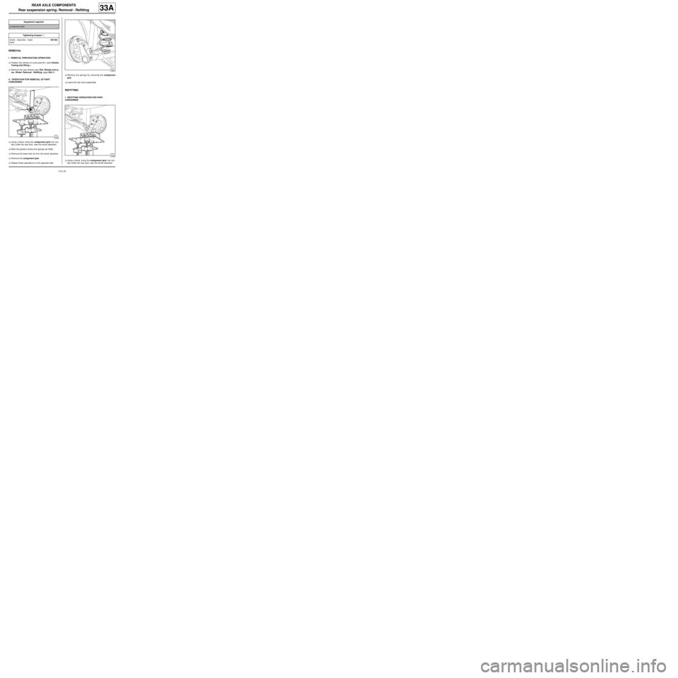
CONCERNED
aUsing a block, bring the component jack into con-
tact under the rear axle, near the shock absorber.
aMark the position where the springs are fitted.
aRemove the lower bolt (1) from the shock absorber.
aRemove the component jack.
aRepeat these operations on the opposite side.aRemove the springs by removing the component
jack.
aLeave the rear axle suspended.
REFITTING
I - REFITTING OPERATION FOR PART
CONCERNED
aUsing a block, bring the component jack into con-
tact under the rear axle, near the shock absorber. Equipment required
component jack
Tightening torquesm
shock absorber lower
bolts105 Nm
119340
119547
119546
Page 139 of 281
33A-41
REAR AXLE COMPONENTS
Complete rear axle system: Removal - Refitting
33A
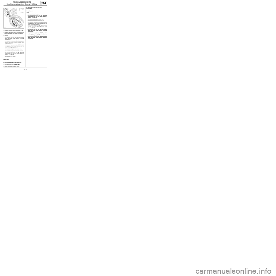
aUnclip the end of the parking brake cables at (10) .
aUnclip the cable sleeve stops at (11) and extract the
parking brake cables from the rear drum flanges.
aRemove:
-the rear brake pads (see 33A, Rear axle compo-
nents, Rear brake lining: Removal - Refitting,
page 33A-14) ,
-the rear brake cylinders (see 33A, Rear axle com-
ponents, Rear brake cylinder: Removal - Refit-
ting, page 33A-17) ,
-the rear wheel speed sensors (see 38C, Anti-lock
braking system, Rear wheel speed sensor: Re-
moval - Refitting, page 38C-17) ,
-the rear rigid brake pipes from the rear axle,
-the rear rigid brake pipe clips from the rear axle,
-the rear stub axle carriers (see 33A, Rear axle
components, Rear stub axle carrier: Removal -
Refitting, page 33A-32) ,
-the rear brake drum flanges,
REFITTING
I - REFITTING PREPARATIONS OPERATION
aStrap the rear axle onto the (Mot. 1390).
aPosition the rear axle under the vehicle.II - REFITTING OPERATION FOR PART
CONCERNED
1 - Replacement
aRefit:
-the rear brake drum flanges,
-the rear stub axle carriers (see 33A, Rear axle
components, Rear stub axle carrier: Removal -
Refitting, page 33A-32) ,
-the rigid brake pipe clips on the rear axle,
-the rear rigid brake pipes from the rear axle,
-the rear wheel speed sensors (see 38C, Anti-lock
braking system, Rear wheel speed sensor: Re-
moval - Refitting, page 38C-17) ,
-the rear brake cylinders (see 33A, Rear axle com-
ponents, Rear brake cylinder: Removal - Refit-
ting, page 33A-17) ,
-the rear brake pads (see 33A, Rear axle compo-
nents, Rear brake lining: Removal - Refitting,
page 33A-14) .
-the parking brake cables (see 37A, Mechanical
component controls, Parking brake cables: Re-
moval - Refitting, page 37A-74) ,
-the rear brake drums (see 33A, Rear axle compo-
nents, Rear brake drum: Removal - Refitting,
page 33A-19) .
121331
Page 142 of 281
35A-2
WHEELS AND TYRES
Wheel: Removal - Refitting
35A
If this procedure does not work:
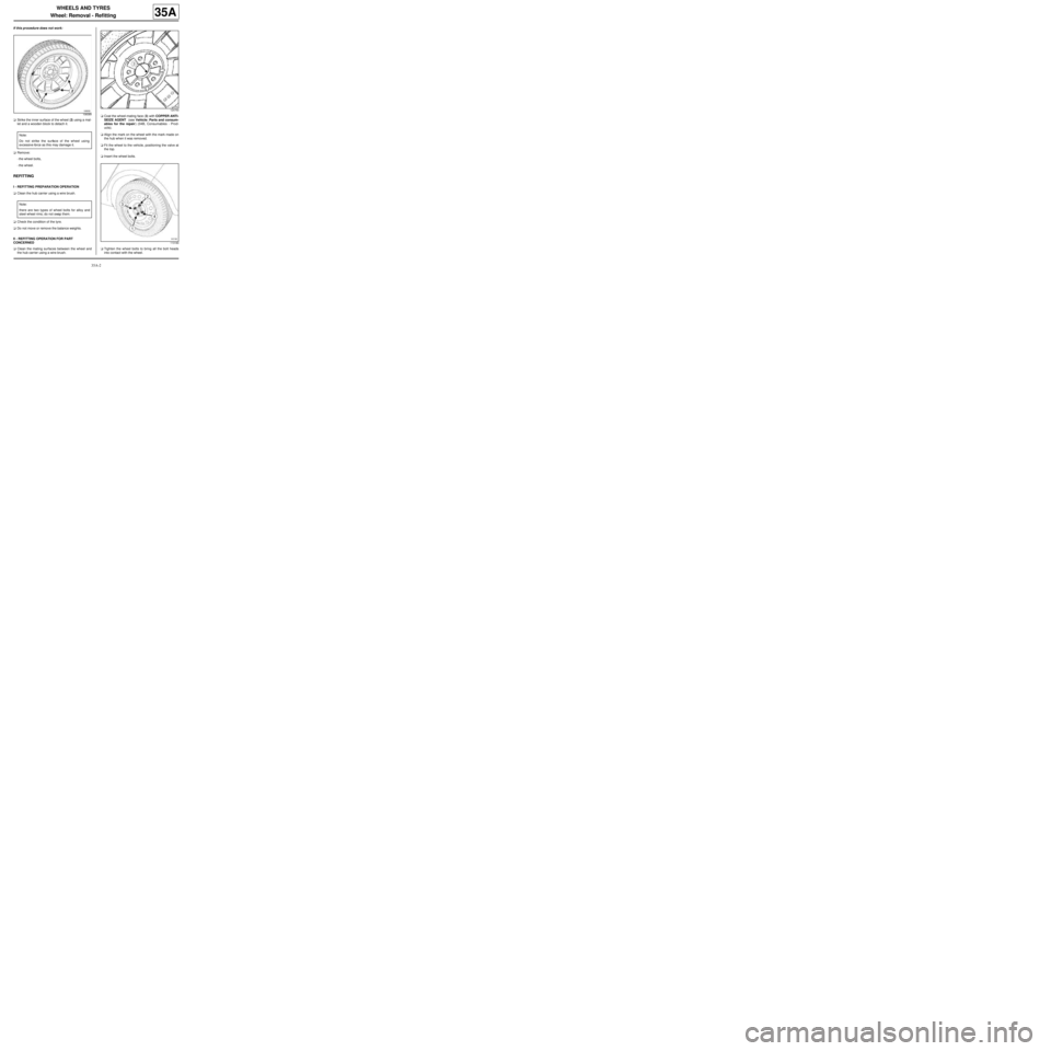
aStrike the inner surface of the wheel (2) using a mal-
let and a wooden block to detach it.
aRemove:
-the wheel bolts,
-the wheel.
REFITTING
I - REFITTING PREPARATION OPERATION
aClean the hub carrier using a wire brush.
aCheck the condition of the tyre.
aDo not move or remove the balance weights.
II - REFITTING OPERATION FOR PART
CONCERNED
aClean the mating surfaces between the wheel and
the hub carrier using a wire brush.aCoat the wheel-mating face (3) with COPPER ANTI-
SEIZE AGENT (see Vehicle: Parts and consum-
ables for the repair) (04B, Consumables - Prod-
ucts).
aAlign the mark on the wheel with the mark made on
the hub when it was removed.
aFit the wheel to the vehicle, positioning the valve at
the top.
aInsert the wheel bolts.
aTighten the wheel bolts to bring all the bolt heads
into contact with the wheel.
106089
Note:
Do not strike the surface of the wheel using
excessive force as this may damage it.
Note:
there are two types of wheel bolts for alloy and
steel wheel rims; do not swap them.
124750
113180
Page 145 of 281
35A-5
WHEELS AND TYRES
Wheel: Balancing
35A
aIn some countries, the use of lead weights is forbid-
den; in this case it is recommended to use ZAMAK
weights instead.
Only use weights provided by the Parts Department.
aRemove the wheels (see 35A, Wheels and tyres,
Wheel: Removal - Refitting, page 35A-1) .
aAlways clean the wheel, disc, and hub bearing sur-
faces.
III - PROCEDURE FOR BALANCING THE WHEEL IN
QUESTION
aMake sure that the wheel balancer bearing surface
and all the centring equipment (ring, thrust plate,
etc.) are kept clean.
aTry not to scratch the (alloy) wheel rim with the
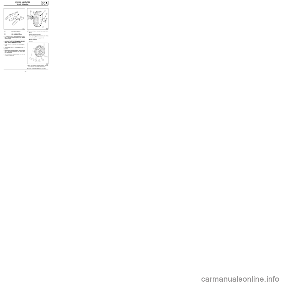
wheel tightening device.aThe wheel is fitted on the wheel balancer as follows:
- (5) ring,
- (6) wheel balancer back-plate,
- (7) wheel tightening device (certain alloy wheels
require a device 200 mm in diameter to ensure that
the wheel has been correctly tightened),
- (8) outer wheel plane,
- (9) wheel.
aPlace the wheel on the wheel balancer, with the
valve at the top, then lock the wheel in place.
aRemove any stones trapped in the tyre tread.
113742
(2) Steel wheel with flange
(3) Alloy wheel with flange
(4) Alloy wheel without flange
105871
100681
Page 153 of 281
36A-2
STEERING ASSEMBLY
Track rod: Removal - Refitting
36A
REMOVAL
I - REMOVAL PREPARATION OPERATION
aPosition the vehicle on a two-post lift (see Vehicle:
Towing and lifting) (02A, Lifting equipment).
aRemove the front wheel (see 35A, Wheels and ty-
res, Wheel: Removal - Refitting, page 35A-1) .
II - OPERATION FOR REMOVAL OF PART
CONCERNED
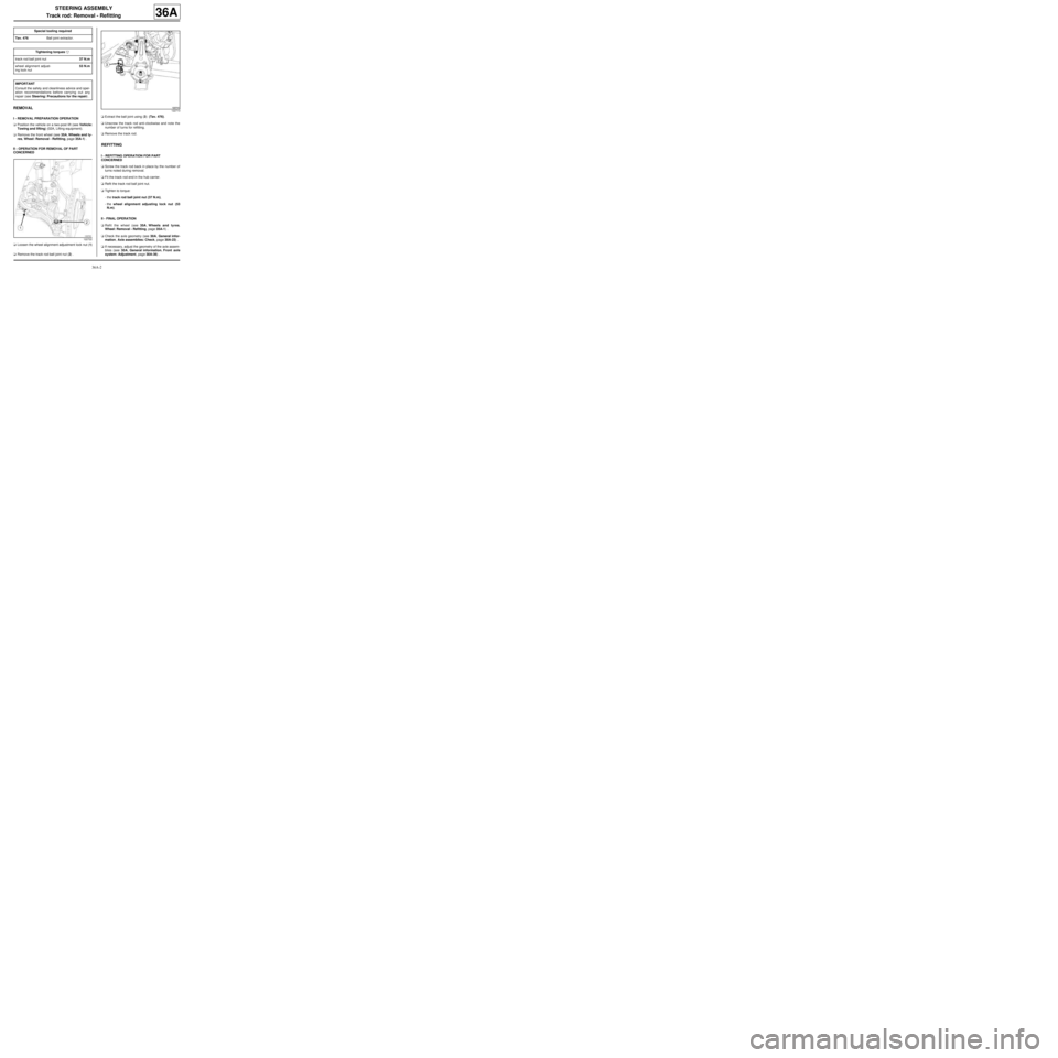
aLoosen the wheel alignment adjustment lock nut (1)
.
aRemove the track rod ball joint nut (2) .aExtract the ball joint using (3) (Tav. 476).
aUnscrew the track rod anti-clockwise and note the
number of turns for refitting.
aRemove the track rod.
REFITTING
I - REFITTING OPERATION FOR PART
CONCERNED
aScrew the track rod back in place by the number of
turns noted during removal.
aFit the track rod end in the hub carrier.
aRefit the track rod ball joint nut.
aTighten to torque:
-the track rod ball joint nut (37 N.m),
-the wheel alignment adjusting lock nut (53
N.m).
II - FINAL OPERATION
aRefit the wheel (see 35A, Wheels and tyres,
Wheel: Removal - Refitting, page 35A-1) .
aCheck the axle geometry (see 30A, General infor-
mation, Axle assemblies: Check, page 30A-23) .
aIf necessary, adjust the geometry of the axle assem-
blies (see 30A, General information, Front axle
system: Adjustment, page 30A-36) . Special tooling required
Tav. 476Ball joint extractor.
Tightening torquesm
track rod ball joint nut37 N.m
wheel alignment adjust-
ing lock nut53 N.m
IMPORTANT
Consult the safety and cleanliness advice and oper-
ation recommendations before carrying out any
repair (see Steering: Precautions for the repair) .
122722
122713
Page 155 of 281
36A-4
STEERING ASSEMBLY
Axial ball joint linkage: Removal - Refitting
36A
REMOVAL
I - REMOVAL PREPARATION OPERATION
aPosition the vehicle on a two-post lift ( (see Vehicle:
Towing and lifting) ).
a
aApply the before repair procedure using the dia-
gnostic tool:
-connect the diagnostic tool,
-select the airbag computer,
-go to repair mode,
-apply the "before repair procedure".
aRemove:
-the front wheel on the side in question (see 35A,
Wheels and tyres, Wheel: Removal - Refitting,
page 35A-1) ,
-the track rod (see 36A, Steering assembly, Track
rod: Removal - Refitting, page 36A-2) ,
-the steering box gaiter (see 36A, Steering assem-
bly, Steering box gaiter: Removal - Refitting,
page 36A-16) .
II - OPERATION FOR REMOVAL OF PART
CONCERNED
aLock the wheels to disengage the rod teeth on the
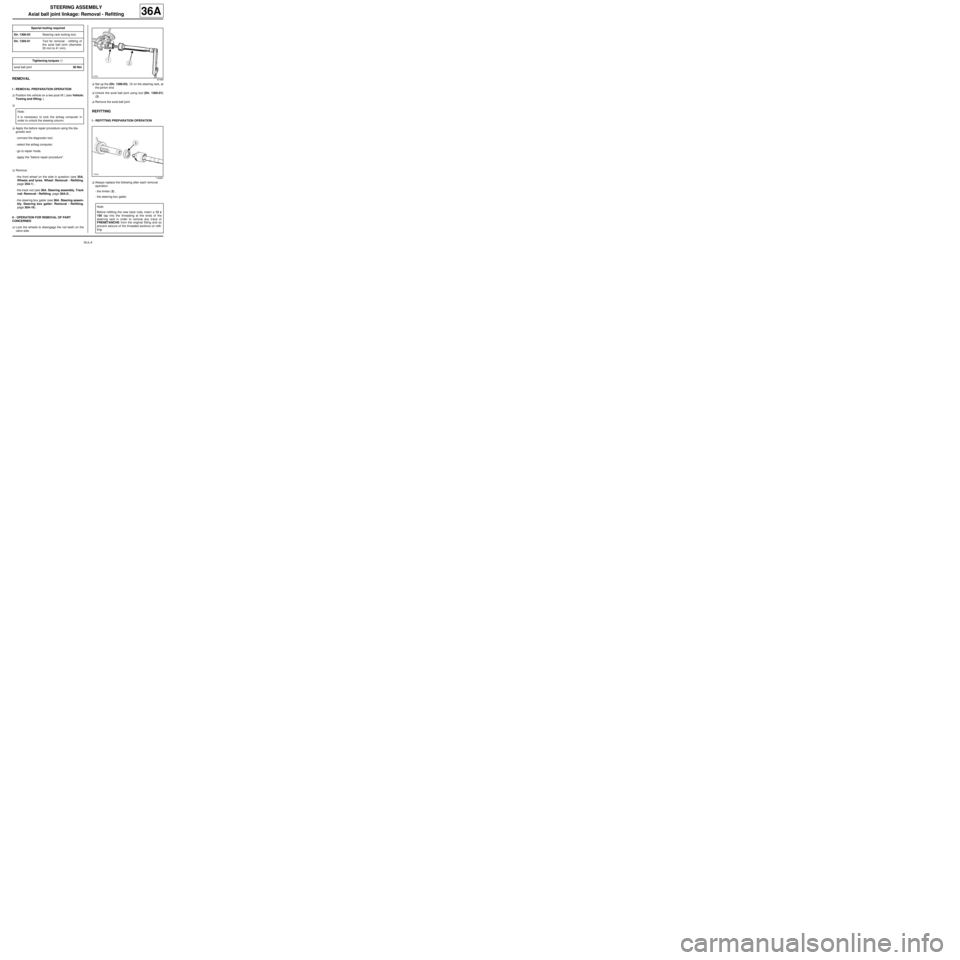
valve side.aSet up the (Dir. 1306-03) (1) on the steering rack, at
the pinion end.
aUnlock the axial ball joint using tool (Dir. 1305-01)
(2) .
aRemove the axial ball joint.
REFITTING
I - REFITTING PREPARATION OPERATION
aAlways replace the following after each removal
operation:
-the limiter (3) ,
-the steering box gaiter. Special tooling required
Dir. 1306-03Steering r ack locking tool.
Dir. 1305-01Tool for removal - refitting of
the axial ball joint (diameter
35 mm to 41 mm).
Tightening torquesm
axial ball joint50 Nm
Note:
It is necessary to lock the airbag computer in
order to unlock the steering column.
97469
116991
Note:
Before refitting the new track rods, inser t a 12 x
100 tap into the threading at the ends of the
steer ing rack in order to remove any trace of
FRENETANCHE from the original fitting and so
pre vent seizure of the threaded sections on refit-
ting.