light RENAULT TWINGO RS 2009 2.G Chasiss Workshop Manual
[x] Cancel search | Manufacturer: RENAULT, Model Year: 2009, Model line: TWINGO RS, Model: RENAULT TWINGO RS 2009 2.GPages: 281
Page 20 of 281
30A-16
GENERAL INFORMATION
Rigid brake pipe: Repair
30A
a
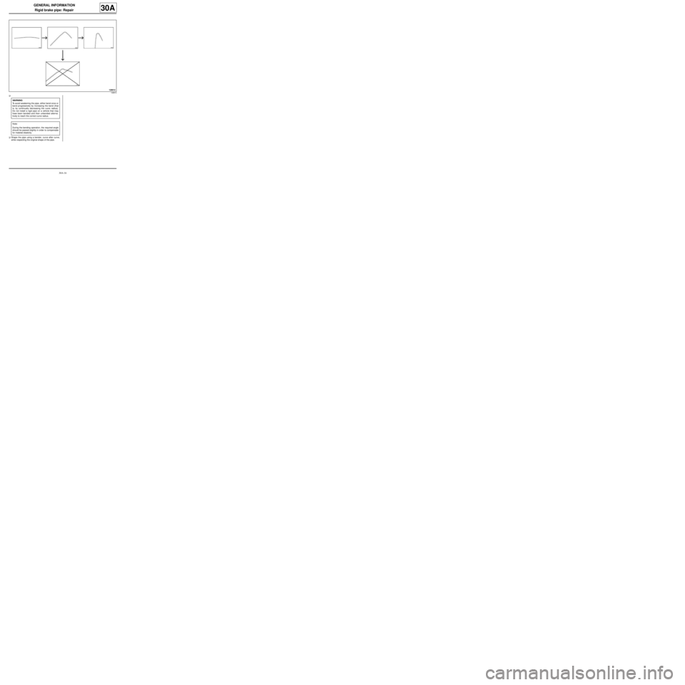
aShape the pipe using a bender, curve after curve,
while respecting the original shape of the pipe.
128814
WARNING
To avoid weakening the pipe, either bend once or
bend progressively by increasing the bend (that
is, by continually decreasing the curve radius).
Do not install a rigid pipe on a vehicle that may
have been bended and then unbended alterna-
tively to reach the correct curve radius.
Note:
During the bending operation, the required angle
should be passed slightly in order to compensate
for material elasticity.
Page 22 of 281

30A-18
GENERAL INFORMATION
Brake fluid: Specifications
30A
BRAKE FLUID REPLACEMENT INTERVAL
Our braking technology, and in particular the disc
brakes (hollow pistons which conduct little heat, have a
low volume of fluid in the cylinder, sliding callipers
avoiding the need for a fluid reserve in the least cooled
area of the wheel), has allowed us to prevent the risk of
« vapour lock » as far as possible, even with heavy
braking (mountainous area). However, current brake
fluids are subject to minor deterioration during the first
months of use due to slight humidity intake. This is why
it is recommended that you change the brake fluid: see
maintenance booklet for the vehicle.
1 - Topping up the level
Wear of the brake pads will result in a gradual drop in
the fluid level in the reservoir.
Do not top up the fluid, as the level will rise again when
the pads are next changed. The brake fluid level must
not fall below the minimum mark.
2 - Approved brake fluid
Mixing two incompatible brake fluids in the brake circuit
may lead to:
-serious risk of leakage due mainly to deterioration of
the cups,
-deterioration in the operation of the ESP system.
To prevent such risks, it is essential to use only brake
fluids that comply with the RENAULT standard (see
Vehicle: Parts and consumables for the repair) .
Page 53 of 281
31A-10
FRONT AXLE COMPONENTS
Front brake calliper: Removal - Refitting
EQ UIPMENT LEVEL SPORT
31A
REMOVAL
I - REMOVAL PREPARATION OPERATION
aPosition the vehicle on a two-post lift (see Vehicle:
Towing and lifting) (02A, Lifting equipment).
aRemove the front wheel (see 35A, Wheels and ty-
res, Wheel: Removal - Refitting, page 35A-1) .
aFit a pedal press on the brake pedal to limit the out-
flow of brake fluid.II - REMOVAL OPERATION
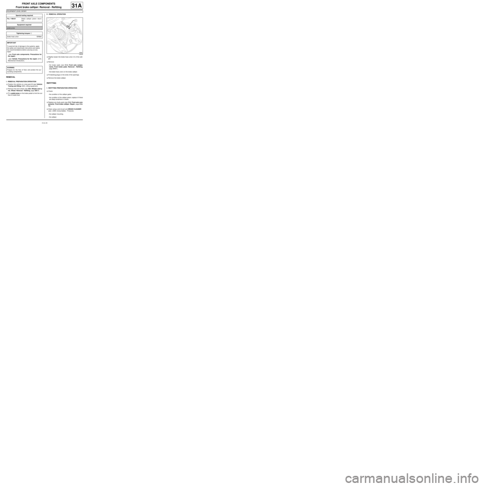
aSlightly loosen the brake hose union (1) of the calli-
per.
aRemove:
-the brake pads (see 31A, Front axle compo-
nents, Front brake pads: Removal - Refitting,
page 31A-1) ,
-the brake hose union on the brake calliper.
aFit blanking plugs on the ends of the openings.
aRemove the brake calliper.
REFITTING
I - REFITTING PREPARATION OPERATION
aCheck:
-the condition of the calliper gaiter,
-the condition of the calliper piston; replace it if there
are deep scratches or cracks.
aReplace any faulty parts (see 31A, Front axle com-
ponents, Front brake calliper: Repair, page 31A-
12) .
aClean using a wire brush and BRAKE CLEANER
(see ) (04B, Consumables - Products):
-the calliper mounting,
-the calliper. Special tooling required
Fre. 1190-01Brake calliper piston return
tool.
Equipment required
pedal press
Tightening torquesm
brake hose union13 N.m
IMPORTANT
To avoid all risk of damage to the systems, apply
the safety and cleanliness instructions and opera-
tion recommendations before carrying out any
repair:
- (see Front axle components: Precautions for
the repair) ,
- (see Vehicle: Precautions for the repair) (01D,
Mechanical introduction).
WARNING
Prepare for the flow of fluid, and protect the sur-
rounding components.
146248
Page 113 of 281
33A-15
REAR AXLE COMPONENTS
Rear brake lining: Removal - Refitting
33A
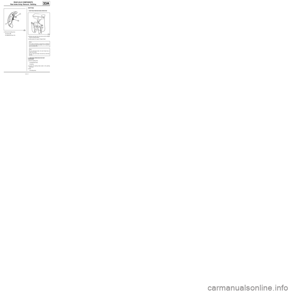
aRemove the leading shoe:
-the spring (10) ,
-the adjustment lever (11) .
REFITTING
I - REFITTING PREPARATIONS OPERATION
aRemove any dust from the drums and the flanges
using the cleaning station.
aLightly grease the support linkage thread.
II - REFITTING OPERATION FOR PART
CONCERNED
aRefit the leading shoe:
-the adjustment lever,
-the spring.
aConnect the parking brake cable to the parking
brake lever.
aRefit:
-the trailing shoe.
86559
117348
Note:
The brake mechanism components are different
on the left and r ight-hand sides, so it is important
not to confuse them.
Note:
On the left-hand brake: the bolt thread has a
right-hand thread.
On the right-hand brake: the bolt has a left-hand
thread.
Page 158 of 281
36A-7
STEERING ASSEMBLY
Steering column: Removal - Refitting
LEFT-HAND DRIVE
36A
REMOVAL
I - REMOVAL PREPARATION OPERATION
aUnlock the steering column.
aLock the airbag computer using the Diagnostic tool
(see Fault finding - Replacement of components)
(MR 413, 88C, Airbags - Pretensioners).
aDisconnect the battery (see Battery: Removal - Re-
fitting) (MR 411, 80A, Battery).
aSet the wheels straight ahead.
aRemove:
-the driver's front airbag (see Driver's frontal air-
bag: Removal - Refitting) (MR 411, 88C, Airbags
- Pretensioners),
-the steering wheel (see 36A, Steering assembly,
Steering wheel: Removal - Refitting, page 36A-
23) ,-the steering column switch assembly (see Steer-
ing column switch assembly: Removal - Refit-
ting) (MR 411, 84A, Steering column switch
assembly),
-the immobiliser antenna/transponder ring (see
Transponder ring: Removal - Refitting) (MR
411, 82A, Immobiliser),
-the ignition switch if the steering column is replaced
(see Ignition switch: Removal - Refitting) (MR
411, 82A, Immobiliser).
II - REMOVAL OPERATION FOR PART
CONCERNED
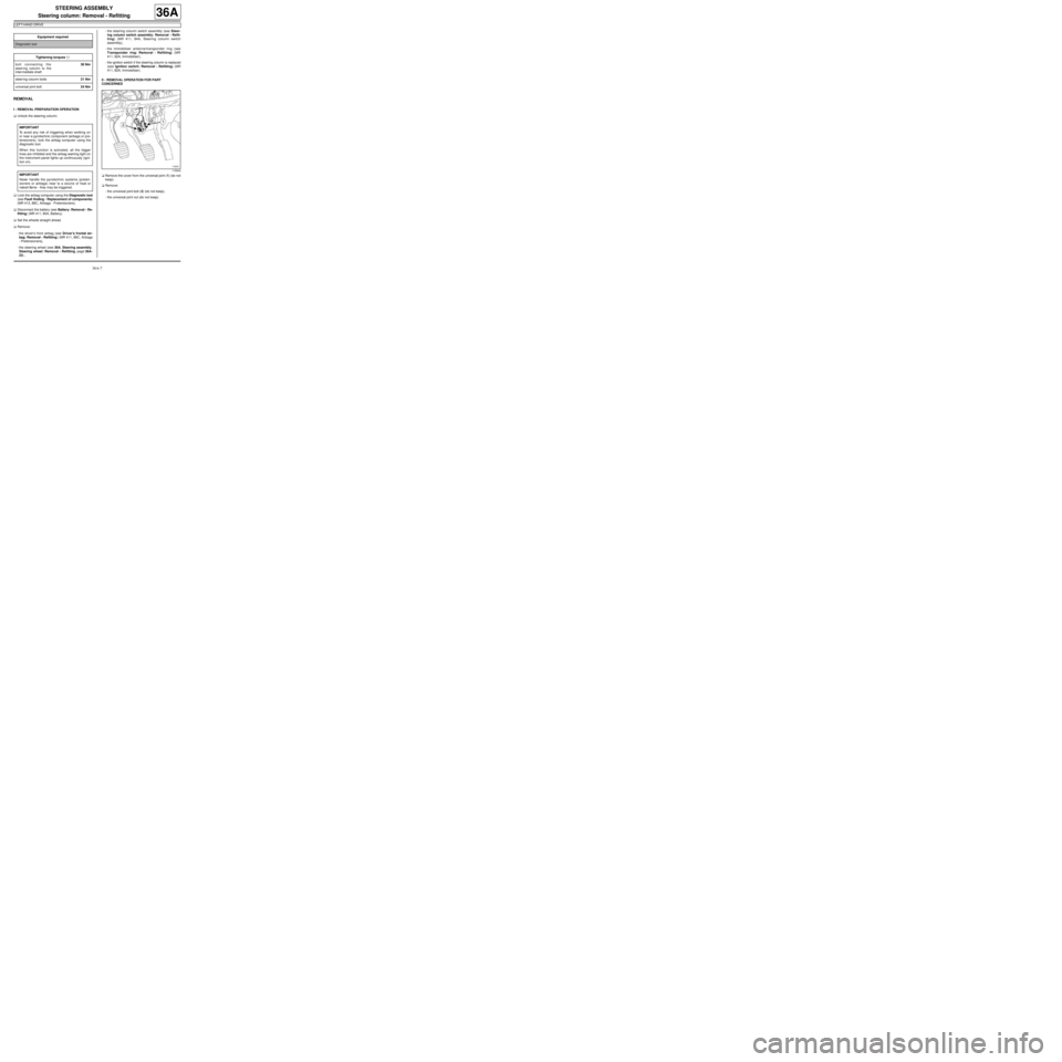
aRemove the cover from the universal joint (1) (do not
keep).
aRemove:
-the universal joint bolt (2) (do not keep),
-the universal joint nut (do not keep). Equipment required
Diagnostic tool
Tightening torquesm
bolt connecting the
steering column to the
inter mediate shaft30 Nm
steer ing column bolts21 Nm
universal joint bolt24 Nm
IMPORTANT
To avoid any risk of triggering when working on
or near a pyrotechnic component (airbags or pre-
tensioners), lock the airbag computer using the
diagnostic tool.
When this function is activated, all the trigger
lines are inhibited and the airbag warning light on
the instrument panel lights up continuously (igni-
tion on).
IMPORTANT
Never handle the pyrotechnic systems (preten-
sioners or airbags) near to a source of heat or
naked flame - they may be triggered.
119544
Page 162 of 281
36A-11
STEERING ASSEMBLY
Steering column: Removal - Refitting
RIGHT-HAND DRIVE
36A
REMOVAL
I - REMOVAL PREPARATION OPERATION
aUnlock the steering column.
a
Lock the airbag computer using the Diagnostic tool
(see Fault finding - Replacement of components)
(MR 413, 88C, Airbags and seat belt pretensioners).
aDisconnect the battery (see Battery: Removal - Re-
fitting) (MR 411, 80A, Battery).
aRemove:
-the driver's front airbag (see Driver's frontal air-
bag: Removal - Refitting) (MR 411, 88C, Airbags
and pretensioners),
-the steering wheel (see 36A, Steering assembly,
Steering wheel: Removal - Refitting, page 36A-
23) .aRemove the rev counter (see Rev counter: Remov-
al - Refitting) (MR 411, 83A, Instrument panel).
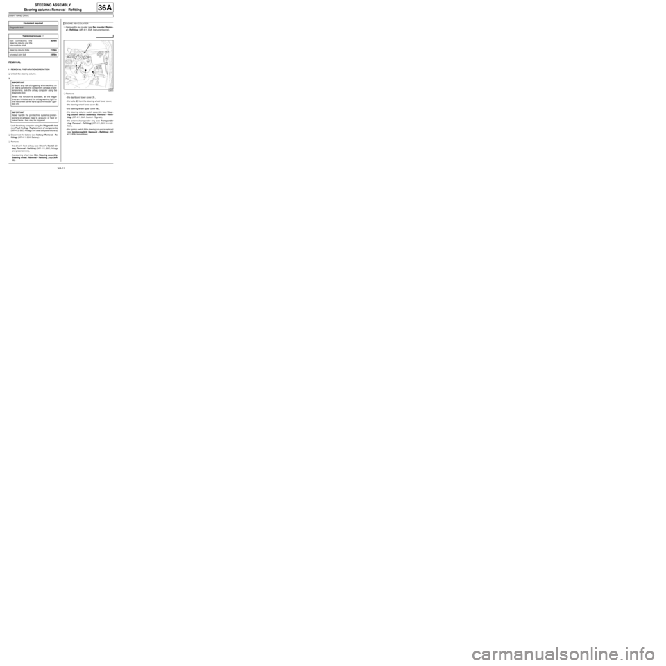
aRemove:
-the dashboard lower cover (1) ,
-the bolts (2) from the steering wheel lower cover,
-the steering wheel lower cover (3) ,
-the steering wheel upper cover (4) ,
-the steering column switch assembly (see Steer-
ing column switch assembly: Removal - Refit-
ting) (MR 411, 84A, Control - Signals),
-the antenna/transponder ring (see Transponder
ring: Removal - Refitting) (MR 411, 82A, Immobi-
liser),
-the ignition switch if the steering column is replaced
(see Ignition switch: Removal - Refitting) (MR
411, 82A, Immobiliser). Equipment required
Diagnostic tool
Tightening torquesm
bolt connecting the
steer ing column and the
inter mediate shaft30 Nm
steer ing column bolts21 Nm
universal joint bolt24 Nm
IMPORTANT
To avoid any risk of triggering when working on
or near a pyrotechnic component (airbags or pre-
tensioners), lock the airbag computer using the
diagnostic tool.
When this function is activated, all the trigger
lines are inhibited and the airbag warning light on
the instrument panel lights up continuously (igni-
tion on).
IMPORTANT
Never handle the pyrotechnic systems (preten-
sioners or airbags) near to a source of heat or
naked flame - they may be triggered.
ENGINE REV COUNTER
123870
Page 211 of 281
37A-32
MECHANICAL COMPONENT CONTROLS
Brake pedal: Removal - Refitting
RIGHT-HAND DRIVE, and 5-SPEED MANUAL GEARBOX
37A
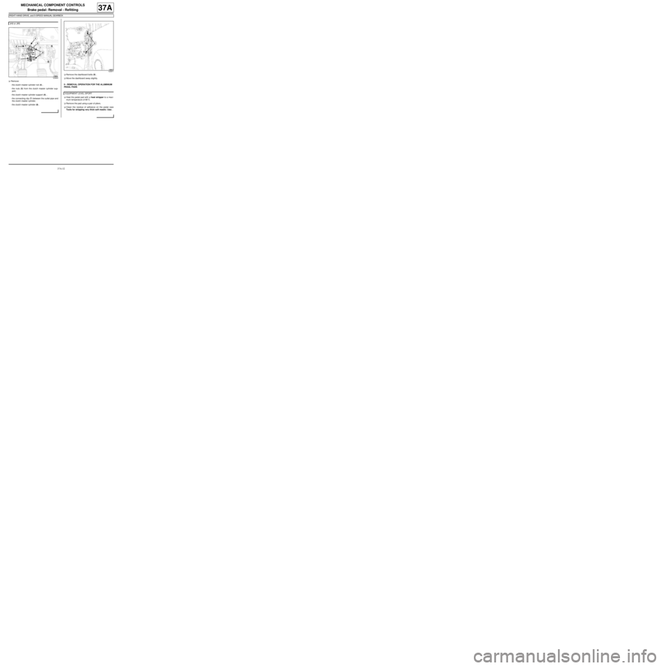
aRemove:
-the clutch master cylinder rod (4) ,
-the nuts (5) from the clutch master cylinder sup-
port,
-the clutch master cylinder support (6) ,
-the connecting clip (7) between the outlet pipe and
the clutch master cylinder,
-the clutch master cylinder (8) .aRemove the dashboard bolts (9) .
aMove the dashboard away slightly.
II - REMOVAL OPERATION FOR THE ALUMINIUM
PEDAL PADS
aHeat the pedal pad with a heat stripper to a maxi-
mum temperature of 80˚C.
aRemove the pad using a pair of pliers.
aClean the residue of adhesive on the pedal (see
Tools for stripping very thick soft mastic: Use) . JH3 or JR5
123904
123871
EQUIPMENT LEVEL SPORT
Page 216 of 281
37A-37
MECHANICAL COMPONENT CONTROLS
Brake pedal: Removal - Refitting
5-SPEED MANUAL SEQUENTIAL GEARBOX
37A
REMOVAL
I - REMOVAL PREPARATION OPERATION
aDisconnect the battery (see Battery: Removal - Re-
fitting) .
aMark the routing of the dashboard wiring harness on
the pedals.
a
Disconnect:
-the accelerator pedal potentiometer connector,
-the electric steering computer supply connector.
aDetach the dashboard wiring harness from the ped-
als.
aMark the brake light switch wiring routing on the ped-
als.
aDetach the brake light switch wiring from the pedals.
aRemove the brake light switch (see 37A, Mechani-
cal component controls, Brake pedal switch: Re-
moval - Refitting, page 37A-42) .II - REMOVAL OPERATION FOR PART
CONCERNED
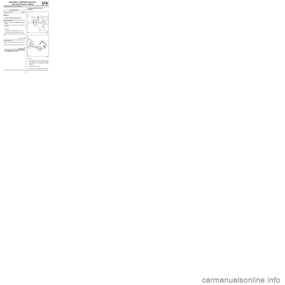
aRemove:
-the connecting shaft (1) between the brake pedal
and the brake servo rod, after tilting the connecting
shaft upwards, move the ring using a flat-blade
screwdriver,
-the brake pedal plate nuts (2) ,
-the « brake pedal - brake pedal plate » assembly. Tightening torquesm
brake pedal plate nuts21 Nm
RIGHT-HAND DRIVE
LEFT-HAND DRIVE
122227
109205
Page 217 of 281
37A-38
MECHANICAL COMPONENT CONTROLS
Brake pedal: Removal - Refitting
5-SPEED MANUAL SEQUENTIAL GEARBOX
37A
REFITTING
I - REFITTING PREPARATIONS OPERATION
aThe shaft connecting the brake servo pushrod and
the brake pedal must be replaced every time it is re-
moved.
II - REFITTING OPERATION FOR PART
CONCERNED
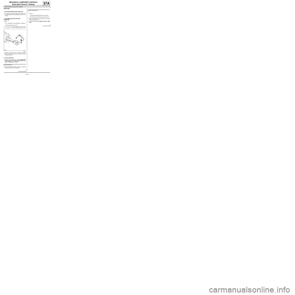
aRefit:
-the « brake pedal - brake pedal plate » assembly,
-the brake pedal plate nuts (2) .
aTorque tighten the brake pedal plate nuts (21 Nm).
aRefit the connecting shaft (1) between the brake
pedal and the brake servo rod from right to left and
from top to bottom.
III - FINAL OPERATION.
aRefit the brake light switch (see 37A, Mechanical
component controls, Brake pedal switch: Re-
moval - Refitting, page 37A-42) .
aRefit the brake light switch wiring in the position
marked during the removal operation.a
Connect:
-the accelerator pedal potentiometer connector,
-the electric steering computer supply connector.
aRefit the dashboard wiring harness in the position
marked during removal.
aConnect the battery (see Battery: Removal - Refit-
ting) .
109205
LEFT-HAND DRIVE
RIGHT-HAND DRIVE
Page 221 of 281
37A-42
MECHANICAL COMPONENT CONTROLS
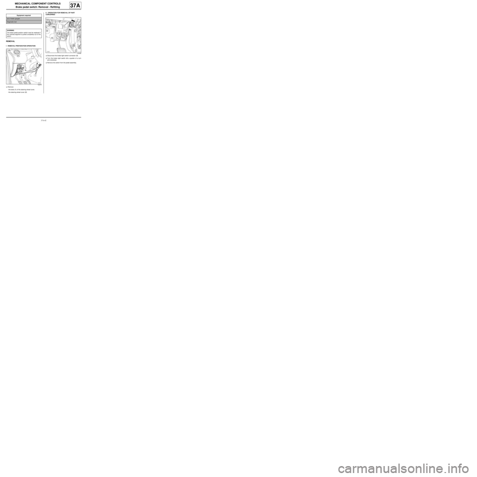
Brake pedal switch: Removal - Refitting
37A
REMOVAL
I - REMOVAL PREPARATION OPERATION
aRemove:
-the bolts (1) of the steering wheel cover,
-the steering wheel cover (2) .II - OPERATION FOR REMOVAL OF PART
CONCERNED
aDisconnect the brake light switch connector (3) .
aTurn the brake light switch (4) a quarter of a turn
anti-clockwise.
aRemove the switch from the pedal assembly. Equipment required
set of feeler gauges
Diagnostic tool
WARNING
The brake pedal position switch must be replaced if
the notched segment is pulled completely out of the
switch.
120279
121350