air conditioning RENAULT TWINGO RS 2009 2.G Electrical Equipment - Petrol Injection User Guide
[x] Cancel search | Manufacturer: RENAULT, Model Year: 2009, Model line: TWINGO RS, Model: RENAULT TWINGO RS 2009 2.GPages: 348
Page 26 of 348
17B-26V7 MR-413-X44-17B000$060.mif
PETROL INJECTION
Fault finding – Features17B
SIM 32 Injection
Program no.: D3
Vdiag No.: 44, 4C, 50
and 54
Air conditioning function
The SIM32 computer manages a "Cold Loop" type air conditioning system:
–request for air conditioning by logical link,
–acquisition of pressure in the air conditioning circuit,
–vehicle speed
–air conditioning compressor control,
–fan unit control for the requirements of this function.
The injection computer reconstitutes the power absorbed by the air conditioning compressor and fast idle speed
requests by using the pressure acquired in the air conditioning circuit.
These signals are necessary for adapting the engine management (idling speed regulation, air flow correction, etc.),
for several reasons:
–air conditioning compressor efficiency,
–more engine ruggedness due to torque hesitation caused by the compressor clutching and declutching,
–helping the alternator.
Fan unit 1 and/or 2 requests are reconstituted according to the pressure in the air conditioning circuit and the vehicle
speed. In summary, there are more fan unit requests when the speed is low and the pressure is high.
OCS - Customised Oil Change Interval (does not concern Vdiag 44 and 4C).
This program takes into account the driving style of the user to warn him of the need for an oil service. It counts the
number of revs per minute since the last oil service, corrected by a factor dependent on the oil temperature. When
this number of revs per minute exceeds a certain threshold, the customer is alerted by a message on the instrument
panel informing him that an oil service is required.
After the oil service, the user must reset the oil service interval on the instrument panel.
To find out if the engine concerned uses this programming, consult ET840 Customised Oil Change Interval.
OBD
The OBD programs are as follows:
–catalytic converter fault finding,
–upstream sensor operational fault finding,
–misfire fault finding,
–fuel supply system fault finding.
The misfiring and fuel supply system fault finding is performed continuously. The operational fault finding for the
upstream sensor and the catalytic converter can be only be carried out once per journey, and can never take place
at the same time.
Page 29 of 348
17B-29V7 MR-413-X44-17B000$070.mif
PETROL INJECTION
Fault finding – Role of components17B
SIM 32 Injection
Program no.: D3
Vdiag No.: 44, 4C, 50
and 54
3. INTERSYSTEM ENGINE FUNCTIONS
The intersystem connections relating to the particular requirements of the injection are as follows:
–The instrument panel computer requests illumination of the OBD warning light to warn of an emissions control fault.
–Requests illumination of the Severity level 1 warning light to warn of an operational safety fault related to the
injection system.
–Requests illumination of the Severity level 2 warning light to warn of an operational safety fault or engine
overheating.
–Requests activation of the fan assemblies (GMV) for engine cooling, but also for the air conditioning system and
sequential gearbox (BVR) functions.
–Request for air conditioning compressor switch-off for engine programming requirements such as starting,
performance, anti-stall, overspeed, etc.
–Passenger Compartment Heating Resistor cut-off or setting request for engine programming requirements such as
starting, performance, anti-stall, overspeed, etc.
–Request for gradual engagement of electrical consumers and to limit power: This last function is made possible by
the alternator being operated. This is used to improve the engine handling in critical operating phases, mainly when
idling and when starting. These requests are sent by the UCH via the CAN network where they are converted before
being sent to the alternator.
Page 31 of 348
17B-31V7 MR-413-X44-17B000$070.mif
PETROL INJECTION
Fault finding – Role of components17B
SIM 32 Injection
Program no.: D3
Vdiag No.: 44, 4C, 50
and 54
TDC sensor:
The angular position is measured using a magneto-inductive sensor triggered by the machined teeth on the engine
flywheel. This sensor gives the engine speed as well as the position of the crankshaft for injection.
Refrigerant pressure sensor:
Its role is to measure the refrigerant pressure in the air conditioning circuit.
Engine coolant temperature sensor:
The engine coolant temperature sensor informs the computer of the engine coolant temperature.
Air temperature sensor:
The air temperature sensor is fitted inside the inlet manifold and informs the computer of the temperature of the air
taken in by the engine.
Catalytic converter:
The role of the catalytic converter is to convert pollutant gases into harmless gases.
Cruise control/speed limiter on/off switch:
This switch is used to turn the cruise control/speed limiter on or off.
Fan unit relay:
This relay actuates the motor-driven fan assemblies when a temperature threshold has been exceeded.
Accelerator potentiometer:
The accelerator potentiometer informs the computer of the position of the accelerator pedal (engine load).
Clutch pedal switch:
The clutch pedal switch informs the computer of the clutch pedal status.
Inlet air temperature sensor:
Its role is to measure the air temperature in the inlet circuit.
Pinking sensor:
Its role is to check for pinking in the combustion chamber.
Oil level sensor:
This sensor measures the level of oil in the engine and sends this information to the computer.
Page 35 of 348
17B-35V7 MR-413-X44-17B000$090.mif
17B
SIM 32 Injection
Program no.: D3
Vdiag No.: 44, 4C, 50
and 54
1. COMPUTER REPLACEMENT OR REPROGRAMMING OPERATIONS
Computer replacement or reprogramming for engines with the OCS (customised oil change interval)
function.
For Vdiag 44 and 4C, commands SC001 and SC003 are not accessible.
The system can be programmed via the diagnostic socket using the RENAULT CLIP diagnostic tool (refer to
Technical Note 3585A, COMPUTER PROGRAMMING AND REPROGRAMMING PROCEDURE or follow the
instructions given by the diagnostic tool). Only in Vdiag 54 and certain engines in Vdiag 50:
For Vdiag 50, the procedure below should be followed only if ET840 Customised Oil Change Interval is ACTIVE.
Certain variables linked to the O.C.S and the details of the last four oil services are saved by the computer.
However, all data saved is cleared during a reprogramming operation. When replacing or reprogramming the
computer, it is necessary to save the data from the old computer so it can be written to the new computer
(or reprogrammed). To do this before changing (or reprogramming) the computer, it is necessary to run the request
SC003 Save computer data, and after it has been changed (or reprogrammed), it is necessary to run the request
SC001 Write saved data.
For Vdiag 50, if ET840 Customised Oil Change Interval is INACTIVE, commands SC001 and SC003 should
not be used.
Operations to check before reprogramming the injection computer:
Before reprogramming the injection computer, move the main Cruise control/Speed limiter switch to the rest
position. The information about the cruise control or the speed limiter displayed on the instrument panel
disappears.
Otherwise, if the main switch remains in the cruise control or speed limiter position during and after reprogramming,
the Cruise control/Speed limiter function will not be operational.
The procedure for resetting the function is as follows:
Ignition switched on and main switch in rest position (the computer detects rest position at that moment).
Switch in Cruise control position to activate the Cruise control function.
Switch in Speed limiter position to activate the Speed limiter function.
IMPORTANT:
–Switch on the diagnostic tool (mains or cigarette lighter supply).
–Connect a battery charger.
–Switch off all electrical consumers (lights, interior lighting, air conditioning, radio, etc.).
–Wait for the engine to cool (engine coolant temperature below 60˚C and air temperature below 50˚C).
PETROL INJECTION
Fault finding – Replacement of components
Page 37 of 348
17B-37V7 MR-413-X44-17B000$100.mif
17B
SIM 32 Injection
Program no.: D3
Vdiag No.: 44, 4C, 50
and 54
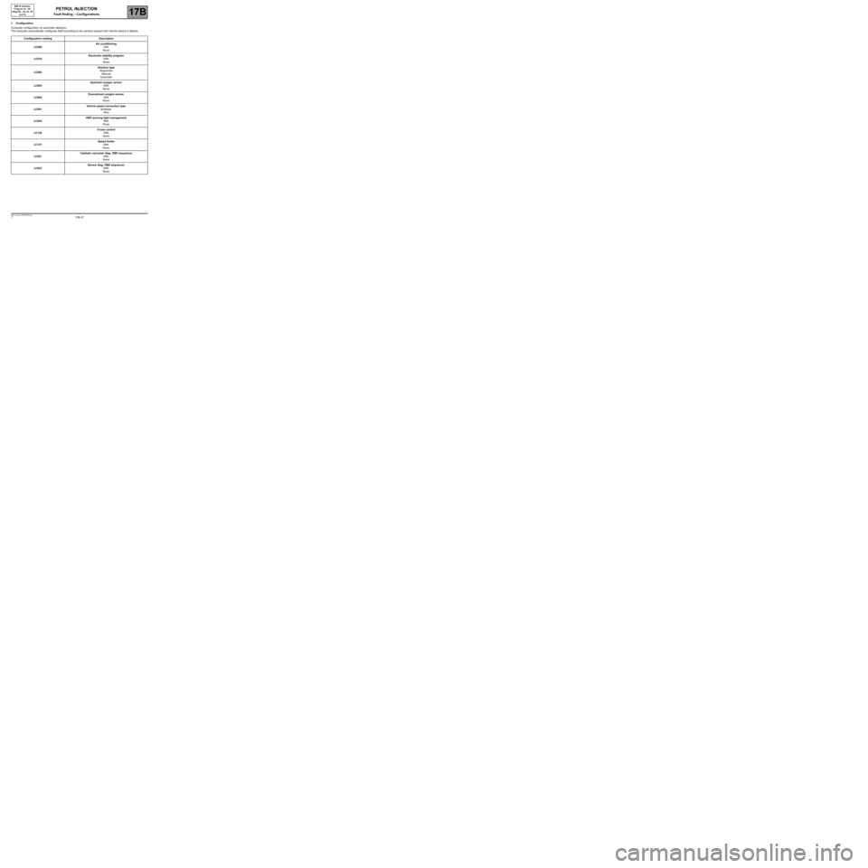
1. Configuration
Computer configuration by automatic detection.
The computer automatically configures itself according to the sensors present and vehicle options it detects.
Configuration readingDescription
LC009
Air conditioning
With
None
LC010
Electronic stability program
With
None
LC005
Gearbox type
Sequential
Manual
Automatic
LC003
Upstream oxygen sensor
With
None
LC004
Downstream oxygen sensor
With
None
LC001
Vehicle speed connection type
Multiplex
Wire
LC024
OBD warning light management
With
None
LC120
Cruise control
With
None
LC121
Speed limiter
With
None
LC021
Catalytic converter diag. OBD sequencer
With
None
LC023
Sensor diag. OBD sequencer
With
None
PETROL INJECTION
Fault finding – Configurations
Page 38 of 348
17B-38V7 MR-413-X44-17B000$100.mif
PETROL INJECTION
Fault finding – Configurations17B
SIM 32 Injection
Program no.: D3
Vdiag No.: 44, 4C, 50
and 54
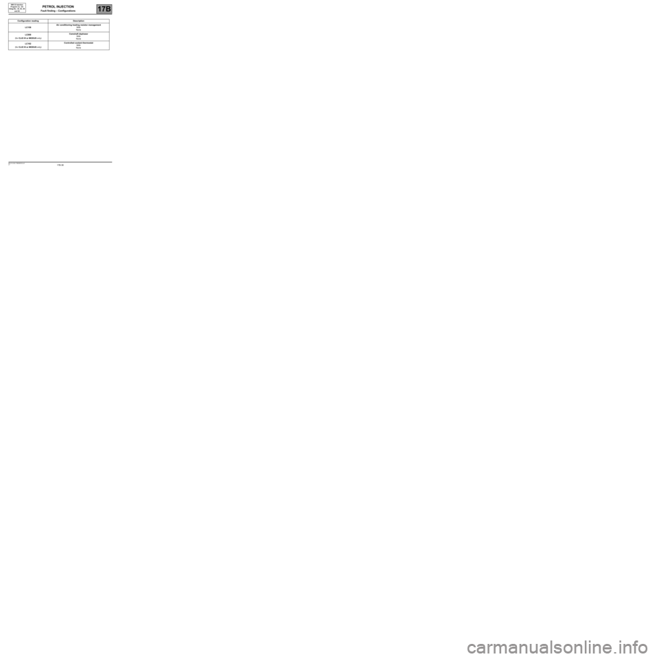
Configuration readingDescription
LC158
Air conditioning heating resistor management
With
None
LC008
(for CLIO III or MODUS only)Camshaft dephaser
With
None
LC162
(for CLIO III or MODUS only)Controlled coolant thermostat
With
None
Page 42 of 348
17B-42V7 MR-413-X44-17B000$120.mif
PETROL INJECTION
Fault finding – Fault summary table17B
SIM 32 Injection
Program no.: D3
Vdiag No.: 44, 4C, 50
and 54
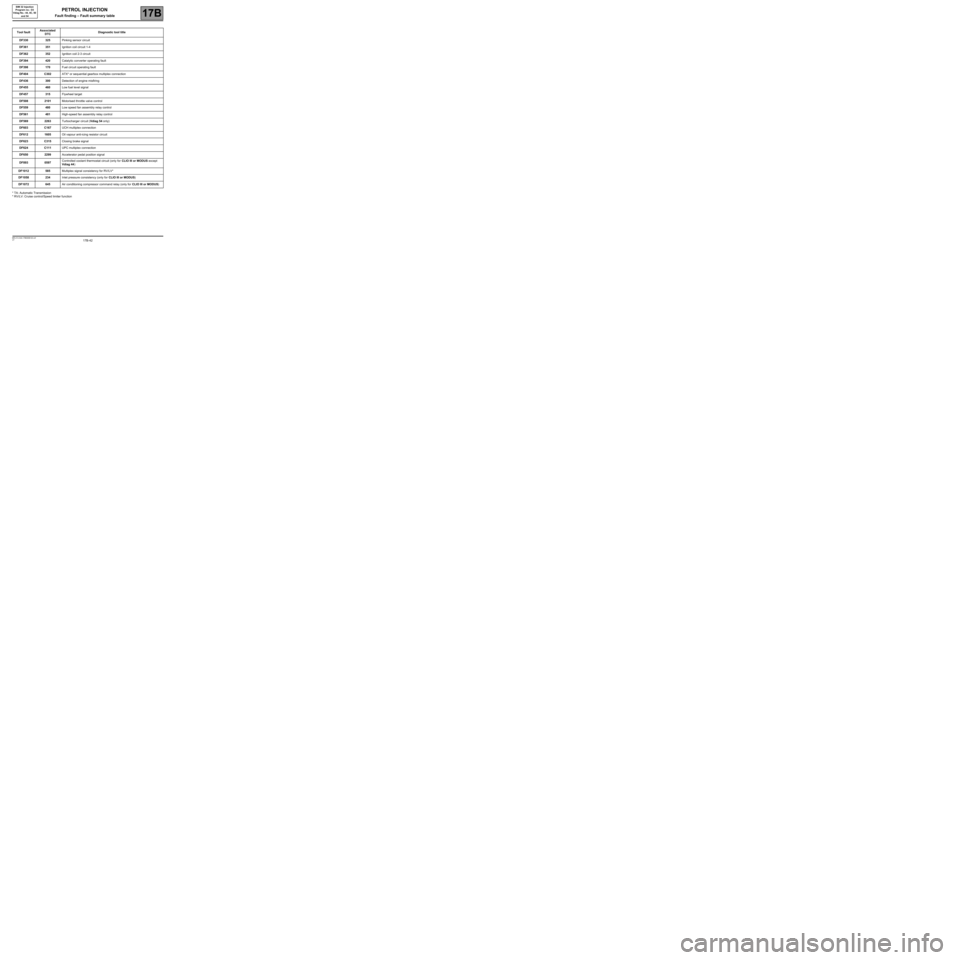
* TA: Automatic Transmission
* RV/LV: Cruise control/Speed limiter function
Tool faultAssociated
DTCDiagnostic tool title
DF330325Pinking sensor circuit
DF361351Ignition coil circuit 1-4
DF362352Ignition coil 2-3 circuit
DF394420Catalytic converter operating fault
DF398170Fuel circuit operating fault
DF404C302ATX* or sequential gearbox multiplex connection
DF436300Detection of engine misfiring
DF455460Low fuel level signal
DF457315Flywheel target
DF5082101Motorised throttle valve control
DF559480Low speed fan assembly relay control
DF561481High-speed fan assembly relay control
DF5692263Turbocharger circuit (Vdiag 54 only)
DF603C167UCH multiplex connection
DF6121605Oil vapour anti-icing resistor circuit
DF623C315Closing brake signal
DF624C111UPC multiplex connection
DF6502299Accelerator pedal position signal
DF8930597Controlled coolant thermostat circuit (only for CLIO III or MODUS except
Vdiag 44)
DF1012585Multiplex signal consistency for RV/LV*
DF1058234Inlet pressure consistency (only for CLIO III or MODUS)
DF1072645Air conditioning compressor command relay (only for CLIO III or MODUS)
Page 131 of 348
17B-131V7 MR-413-X44-17B000$133.mif
PETROL INJECTION
Fault finding – Interpretation of faults17B
SIM 32 Injection
Program no.: D3
Vdiag No.: 44, 4C, 50
and 54
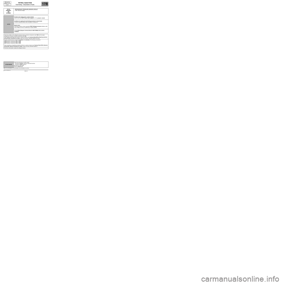
DF232
PRESENT
OR
STOREDREFRIGERANT PRESSURE SENSOR CIRCUIT
1.DEF: Abnormal voltage
NOTESPriorities when dealing with a number of faults:
Deal first with fault DF011 Sensor feed voltage no. 1 if it is present or stored.
Conditions for applying the fault finding procedure to stored faults:
The fault is declared present when the ignition is switched on.
Special notes:
If the fault is present or stored, parameter PR037 Refrigerant pressure displays a safe
value of 0 bar, and the air conditioning no longer operates.
Use the Wiring Diagrams Technical Note for NEW TWINGO, E33, CLIO III,
or MODUS.
Check the condition of the refrigerant pressure sensor connector (component code 1202) and the engine
management computer connector (component code 120).
If the connectors are faulty and if there is a repair procedure (see Technical Note 6015A, Repairing electrical
wiring, Wiring: Precautions for repair), repair the connector, otherwise replace the wiring.
Use the universal bornier to check the insulation and continuity of the following connections:
●38U between components 120 and 1202,
●38X between components 120 and 1202,
●38Y between components 120 and 1202.
If the connection or connections are faulty and there is a repair procedure (see Technical Note 6015A, Electrical
wiring repair, Wiring: Precautions for repair), repair the wiring, otherwise replace it.
If the fault is still present, replace the refrigerant sensor.
SIM32_V44_DF232/SIM32_V4C_DF232/SIM32_V50_DF232/SIM32_V54_DF232
AFTER REPAIRFollow the instructions to confirm repair:
–If the fault is present, continue to deal with the fault.
–If the fault is stored, ignore it.
Deal with any other faults.
Clear the stored faults.
Page 152 of 348
17B-152V7 MR-413-X44-17B000$133.mif
PETROL INJECTION
Fault finding – Interpretation of faults17B
SIM 32 Injection
Program no.: D3
Vdiag No.: 44, 4C, 50
and 54
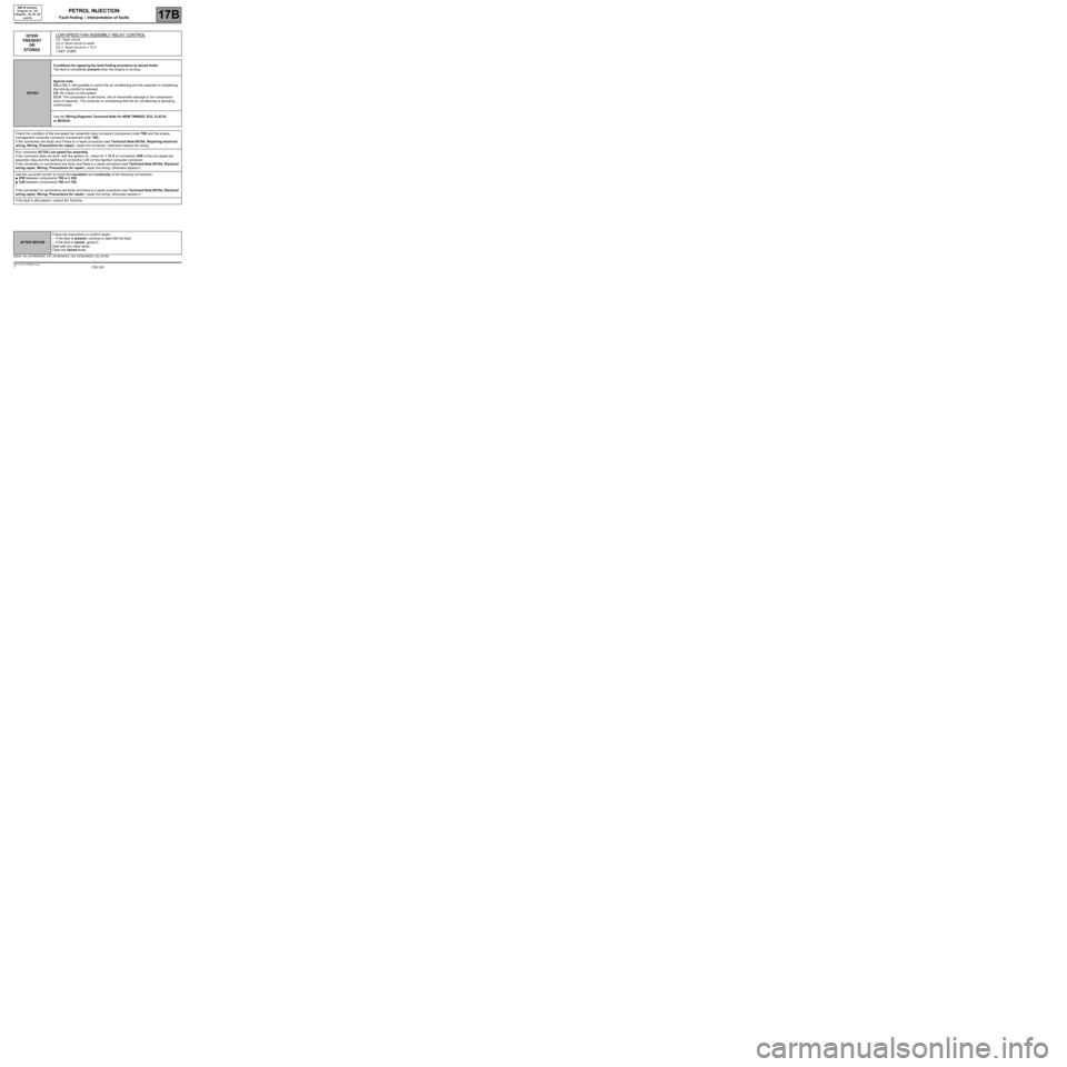
DF559
PRESENT
OR
STOREDLOW-SPEED FAN ASSEMBLY RELAY CONTROLCO: Open circuit
CC.0: Short circuit to earth
CC.1: Short circuit to + 12 V
1.DEF: EOBD
NOTESConditions for applying the fault finding procedure to stored faults
The fault is considered present when the engine is running.
Special note:
CO or CC.1: Not possible to control the air conditioning and the customer is complaining
that driving comfort is reduced.
CO: No impact on the system.
CC.0: The compressor is still active, risk of irreversible damage to the compressor
(loss of capacity). The customer is complaining that the air conditioning is operating
continuously.
Use the Wiring Diagrams Technical Note for NEW TWINGO, E33, CLIO III,
or MODUS.
Check the condition of the low-speed fan assembly relay connector (component code 700) and the engine
management computer connector (component code 120).
If the connectors are faulty and if there is a repair procedure (see Technical Note 6015A, Repairing electrical
wiring, Wiring: Precautions for repair), repair the connector, otherwise replace the wiring.
Run command AC154 Low speed fan assembly.
If the command does not work, with the ignition on, check for + 12 V on connection 3FB of the low-speed fan
assembly relay and the earthing of connection 3JN on the injection computer connector.
If the connection or connections are faulty and there is a repair procedure (see Technical Note 6015A, Electrical
wiring repair, Wiring: Precautions for repair), repair the wiring, otherwise replace it.
Use the universal bornier to check the insulation and continuity of the following connections:
●3FB between components 700 and 238,
●3JN between components 700 and 120.
If the connection or connections are faulty and there is a repair procedure (see Technical Note 6015A, Electrical
wiring repair, Wiring: Precautions for repair), repair the wiring, otherwise replace it.
If the fault is still present, contact the Techline.
SIM32_V44_DF559/SIM32_V4C_DF559/SIM32_V50_DF559/SIM32_V54_DF559
AFTER REPAIRFollow the instructions to confirm repair:
–If the fault is present, continue to deal with the fault.
–If the fault is stored, ignore it.
Deal with any other faults.
Clear the stored faults.
Page 153 of 348
17B-153V7 MR-413-X44-17B000$133.mif
PETROL INJECTION
Fault finding – Interpretation of faults17B
SIM 32 Injection
Program no.: D3
Vdiag No.: 44, 4C, 50
and 54
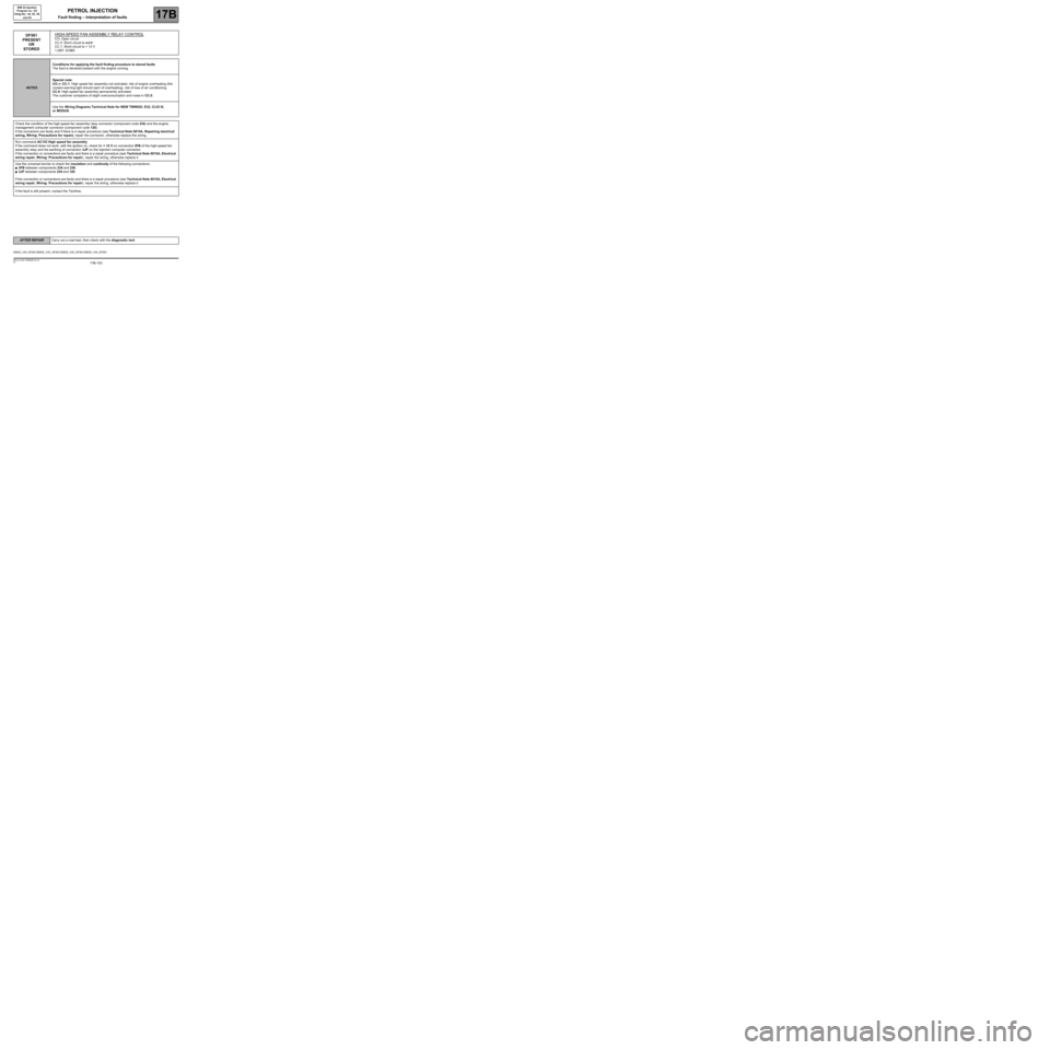
DF561
PRESENT
OR
STOREDHIGH-SPEED FAN ASSEMBLY RELAY CONTROLCO: Open circuit
CC.0: Short circuit to earth
CC.1: Short circuit to + 12 V
1.DEF: EOBD
NOTESConditions for applying the fault finding procedure to stored faults
The fault is declared present with the engine running.
Special note:
CO or CC.1: High speed fan assembly not activated, risk of engine overheating (the
coolant warning light should warn of overheating), risk of loss of air conditioning.
CC.0: High-speed fan assembly permanently activated.
The customer complains of slight overconsumption and noise in CC.0.
Use the Wiring Diagrams Technical Note for NEW TWINGO, E33, CLIO III,
or MODUS.
Check the condition of the high-speed fan assembly relay connector (component code 234) and the engine
management computer connector (component code 120).
If the connectors are faulty and if there is a repair procedure (see Technical Note 6015A, Repairing electrical
wiring, Wiring: Precautions for repair), repair the connector, otherwise replace the wiring.
Run command AC153 High speed fan assembly.
If the command does not work, with the ignition on, check for + 12 V on connection 3FB of the high-speed fan
assembly relay and the earthing of connection 3JP on the injection computer connector.
If the connection or connections are faulty and there is a repair procedure (see Technical Note 6015A, Electrical
wiring repair, Wiring: Precautions for repair), repair the wiring, otherwise replace it.
Use the universal bornier to check the insulation and continuity of the following connections:
●3FB between components 234 and 238,
●3JP between components 234 and 120.
If the connection or connections are faulty and there is a repair procedure (see Technical Note 6015A, Electrical
wiring repair, Wiring: Precautions for repair), repair the wiring, otherwise replace it.
If the fault is still present, contact the Techline.
SIM32_V44_DF561/SIM32_V4C_DF561/SIM32_V50_DF561/SIM32_V54_DF561
AFTER REPAIRCarry out a road test, then check with the diagnostic tool.