warning lights RENAULT TWINGO RS 2009 2.G Electrical Equipment User Guide
[x] Cancel search | Manufacturer: RENAULT, Model Year: 2009, Model line: TWINGO RS, Model: RENAULT TWINGO RS 2009 2.GPages: 241
Page 169 of 241

88A-33
WIRING HARNESS
Engine wiring: Removal - Refitting
D4F or D7F
88A
-the section of wiring on the cylinder block and sub-
frame,
-the section of wiring on the engine cooling fan as-
sembly.
aRemove the engine harness.
REFITTING
I - REFITTING PREPARATIONS OPERATION
aIf replacing with a complete wiring harness, lock the
unused connectors (see Connectors: Sealing and
locking) (Technical Note 6015A, 88A, Wiring).
II - REFITTING OPERATION FOR PART
CONCERNED
aRefit the engine harness.
aConnect the engine cooling fan assembly connector.
aConnect:
-the engine cooling fan assembly connector,
-the engine cooling fan assembly resistor connec-
tor,
-the air conditioning compressor connector,
-the refrigerant fluid pressure sensor connector.
aConnect:
-the engine harness/front of engine wiring connec-
tor,-the connectors to the petrol injection computer,
-the crankshaft position sensor connector,
-the coolant temperature sensor connector,
-the motorised throttle valve connector,
-the air inlet pressure sensor connector,
-the pinking sensor connector,
-the air inlet temperature sensor connector,
-the engine harness/injection wiring connector,
-the alternator connector,
-the radio interference suppressor connector,
-the reversing lights switch connector,
-the downstream oxygen sensor connector,
-upstream oxygen sensor connector,
-the ignition coil connector,
-the fuel vapour absorber connector,
-the oil pressure sensor connector.
aRefit:
-the engine compartment connection unit supply
terminal nut,
-the wiring mounting nut on the battery protection
fuse board,
-the negative battery terminal wiring nuts,
-the positive battery terminal wiring nut,
-the earth wiring nut on the front left-hand side
member,
-the earth wiring nuts on the engine,
-the starter wiring nuts,
-the alternator earth wiring nut.
aClip:
-the section of wiring on the cylinder head,
-the section of wiring on the cylinder block and sub-
frame,
-the section of wiring on the engine cooling fan as-
sembly.
aRefit the engine harness. WARNING
To prevent any damage during the removal ope-
ration, check that the wiring is free from its moun-
tings (retaining clip, plastic clip, adhesive tape,
connector, etc.).
D7F
STANDARD HEATING
AIR CONDITIONING
D4F
Page 172 of 241
88A-36
WIRING HARNESS
Engine wiring: Removal - Refitting
EQ UIPMENT LEVEL SPORT
88A
REMOVAL
I - REMOVAL PREPARATION OPERATION
aPosition the vehicle on a two-post lift (see Vehicle:
Towing and lifting) (02A, Lifting equipment).
aSwitch off the ignition.
aRemove:
-the engine undertray,
-the front wheels (see Wheel: Removal - Refitting)
(35A, Wheels and tyres),-the front wheel arch liners (see Front wheel arch
liner: Removal - Refitting) (55A, Exterior protec-
tion),
-the front bumper (see Front bumper: Removal -
Refitting) (55A, Exterior protection),
-the left-hand headlight (see 80B, Headlights,
Halogen headlight: Removal - Refitting, page
80B-7) ,
-the battery (see 80A, Battery, Battery: Removal -
Refitting, page 80A-2) ,
-the battery tray (see 80A, Battery, Battery tray:
Removal - Refitting, page 80A-6) ,
-the air filter unit (see Air filter unit: Removal - Re-
fitting) (12A, Fuel mixture),
-the windscreen wiper arms (see 85A, Wiping -
Washing, Windscreen wiper arm: Removal - Re-
fitting, page 85A-6) ,
-the scuttle panel grille (see Scuttle panel grille:
Removal - Refitting) (56A, Exterior equipment),
-the scoop under the scuttle panel grille (see Scoop
under the scuttle panel grille: Removal - Refit-
ting) (56A, Exterior equipment).
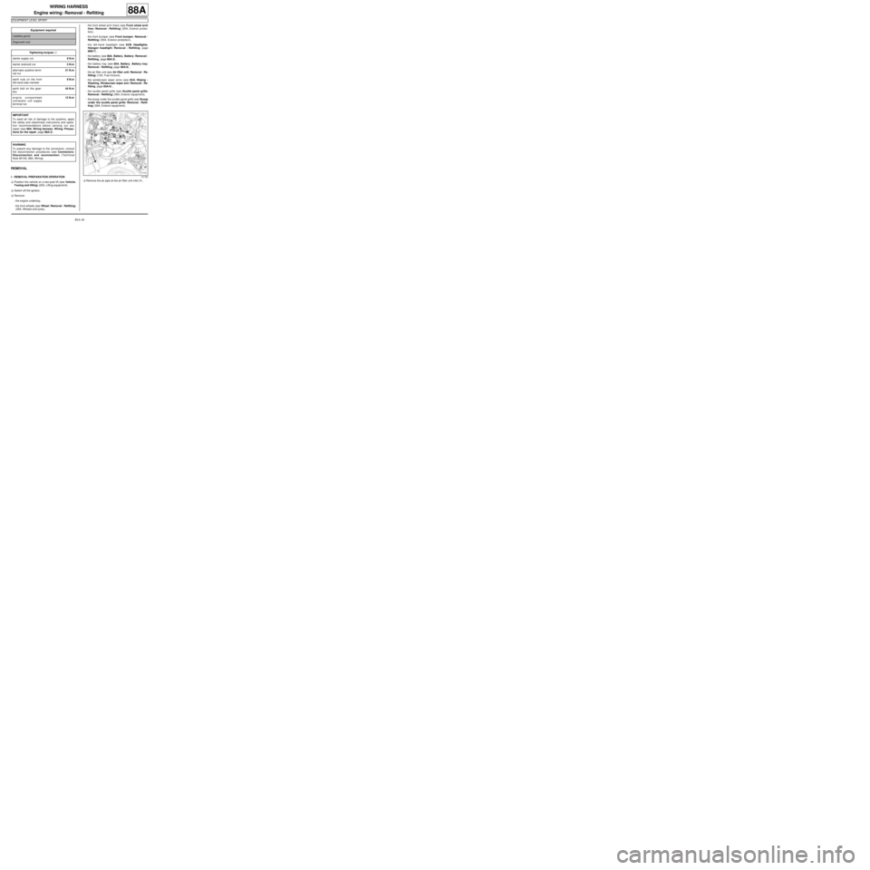
aRemove the air pipe at the air filter unit inlet (1) . Equipment required
indelible pencil
Diagnostic tool
Tightening torquesm
starter supply nut8 N.m
starter solenoid nut5 N.m
alter nator positive termi-
nal nut21 N.m
earth nuts on the front
left-hand side member8 N.m
earth bolt on the gear-
box44 N.m
engine compartment
connection unit supply
terminal nut12 N.m
IMPORTANT
To avoid all risk of damage to the systems, apply
the safety and cleanliness instructions and opera-
tion recommendations before carrying out any
repair (see 88A, Wiring harness, Wiring: Precau-
tions for the repair, page 88A-2) .
WARNING
To prevent any damage to the connectors, consult
the disconnection procedures (see Connectors:
Disconnection and reconnection) (Technical
Note 6015A, 88A, Wiring).
131763
Page 190 of 241
88A-54
WIRING HARNESS
Passenger compartment wiring: Removal - Refitting
LEFT-HAND DRIVE
88A
REMOVAL
I - REMOVAL PREPARATION OPERATION
aPosition the vehicle on a two-post lift (see Vehicle:
Towing and lifting) (MR 411, 02A, Lifting equip-
ment).
aLock the airbag computer using the Diagnostic tool
(see Fault finding - Replacement of components)
(MR 413, 88C, Airbags and pretensioners).
aSwitch off the ignition.
aDisconnect the battery (see 80A, Battery, Battery:
Removal - Refitting, page 80A-2) .aRemove:
-the rear lights on the wing (see 81A, Rear lighting,
Rear wing light: Removal - Refitting, page 81A-
3) ,
-the rear bumper (see Rear bumper: Removal -
Refitting) (MR 412, 55A, Exterior protection),
-the front seats (see Complete front seat: Remo-
val - Refitting) (MR 412, 75A, Front seat frames
and runners),
-the rear bench seat base (see Rear bench seat
base: Removal - Refitting) (MR 412, 76A, Rear
seat frames and runners),
-the rear bench seatback (see Rear bench seat-
back: Removal - Refitting) (MR 412, 76A, Rear
seat frames and runners),
-the driver's side front airbag (see 88C, Air bag and
Pretensioners, Driver's frontal airbag: Removal
- Refitting, page 88C-6) ,
-the steering wheel (see Steering wheel: Removal
- Refitting) (MR 411, 36A, Steering assembly).
aRemove the rev counter (see 83A, Instrument pa-
nel, Rev counter: Removal - Refitting, page 83A-
3) .
aRemove:
-the steering column switch assembly (see 84A,
Control - Signals, Steering column switch as-
sembly: Removal - Refitting, page 84A-2) ,
-the instrument panel (see 83A, Instrument panel,
Instrument panel: Removal - Refitting, page
83A-1) ,
-the passenger front airbag (see 88C, Air bag and
Pretensioners, Passenger's frontal airbag: Re-
moval - Refitting, page 88C-8) ,
-the glovebox (see Glovebox: Removal - Refit-
ting) (MR 412, 57A, Interior equipment),
-the radio (see 86A, Radio, Radio: Removal - Re-
fitting, page 86A-4) ,
-the centre front panel (see Centre front panel: Re-
moval - Refitting) (MR 412, 57A, Interior equip-
ment),
-the hazard warning lights control (see 84A, Con-
trol - Signals, Hazard warning lights and central
door control: Removal - Refitting, page 84A-10)
, Equipment required
Diagnostic tool
IMPORTANT
Consult the safety and cleanliness advice and ope-
ration recommendations before carrying out any
repair (see 88A, Wiring harness, Wiring: Precau-
tions for the repair, page 88A-2) .
IMPORTANT
To avoid any risk of triggering when working on or
near a pyrotechnic component (airbags or preten-
sioners), lock the airbag computer using the dia-
gnostic tool.
When this function is activated, all the trigger lines
are inhibited and the airbag warning light on the ins-
trument panel lights up contin uously (ignition on).
IMPORTANT
Never handle the pyrotechnic systems (pretensio-
ners or airbags) near to a source of heat or naked
flame - they may be triggered.
WARNING
To prevent damaging the connectors, consult the
disconnection procedures (see Connector: Dis-
connection and reconnection) (Technical Note
6015A, 88A, Wiring).
ENGINE REV COUNTER
Page 194 of 241

88A-58
WIRING HARNESS
Passenger compartment wiring: Removal - Refitting
LEFT-HAND DRIVE
88A
-the section of wiring on the floor.
aRemove the passenger compartment wiring.
REFITTING
I - REFITTING PREPARATIONS OPERATION
aIf replacing with more wiring, immobilise the unused
connectors (see Connector: Sealing and immobi-
lising) (Technical Note 6015A, 88A, Wiring).
II - REFITTING OPERATION FOR PART
CONCERNED
aRefit the passenger compartment wiring.
aClip:
-the section of wiring onto the floor,
-the section of wiring onto the dashboard.
aRefit:
-the earth wiring nut on the right-hand side of the
dashboard,
-the passenger compartment wiring / passenger's
door wiring connector bolts.
aConnect the passenger compartment wiring / pas-
senger's door wiring connector.
aRefit the radio earth wiring nut.
aConnect:
-the airbag computer connector,
-the gear lever switch connector,
-the side impact sensor connectors.
aRefit:
-the tunnel earth wiring nut,
-the dashboard cross member earth wiring nut,
-the passenger compartment wiring / driver's door
wiring connector bolts.
aConnect the passenger compartment wiring / dri-
ver's door wiring connector.aConnect the fog light relay connector.
aConnect the passenger compartment wiring / sun-
roof wiring connector.
aConnect:
-the passenger compartment wiring / interior lights
wiring connector,
-the passenger compartment wiring / heating sys-
tem wiring connector,
-the UCH connectors,
-the rear fog light relay connector,
-the dipped headlights relay connector,
-the electric window relay connector,
-the passenger compartment fan assembly relay
connector,
-the passenger compartment fuse box connector,
-the passenger compartment wiring / front left-hand
wiring connectors.
aClip on the rear section of the wiring.
aRefit:
-the rear right-hand earth wiring nut,
-the rear left-hand earth wiring nut.
aConnect:
-the right-hand speaker connector,
-the left-hand speaker connector.
aConnect:
-the parking distance control computer connector, WARNING
To prevent any damage during the removal ope-
ration, check that the wiring is free from its moun-
tings (retaining clip, plastic clip, adhesive tape,
connector, etc.).
FOG LIGHTS
OPENING ROOF
WITH 4 SPEAKERS, WITHOUT RADIO or RADIO
NO. 03
REAR PROXIMITY RADAR
Page 195 of 241
88A-59
WIRING HARNESS
Passenger compartment wiring: Removal - Refitting
LEFT-HAND DRIVE
88A
-the parking distance control buzzer connector.
aConnect:
-the fuel pump connector,
-the rear wheel speed sensor wiring connectors,
-the passenger compartment wiring / tailgate wiring
connectors,
-the parking brake switch connector.
III - FINAL OPERATION.
aRefit:
-the rear wheel arch trim (see Rear wheel arch
trim: Removal - Refitting) (MR 412, 71A, Body in-
ternal trim),
-the rear quarter panel trims (see Quarter panel
trim: Removal - Refitting) (MR 412, 71A, Body in-
ternal trim),
-the rear parcel shelf side trims (see Rear parcel
shelf side trim: Removal - Refitting) (MR 412,
71A, Body internal trim),
-the floor carpets (see Floor carpet: Removal - Re-
fitting) (MR 412, 71A, Body internal trim),
-the rear panel trims (see Rear panel lining: Re-
moval - Refitting) (MR 412, 71A, Body internal
trim),
-the front door sill inner trims (see Front door sill
lining: Removal - Refitting) (MR 412, 71A, Body
internal trim),
-the dashboard (see Dashboard: Removal - Refit-
ting) (MR 412, 57A, Interior equipment),
-the tweeters (see 86A, Radio, Tweeter: Removal
- Refitting, page 86A-7) ,
-the centre console (see Centre console: Removal
- Refitting) (MR 412, 57A, Interior equipment),
-the A-pillar trims (see Windscreen pillar trim: Re-
moval - Refitting) (MR 412, 71A, Body internal
trim),
-the hazard warning lights control (see 84A, Con-
trol - Signals, Hazard warning lights and central
door control: Removal - Refitting, page 84A-10)
,
-the centre front panel (see Centre front panel: Re-
moval - Refitting) (MR 412, 57A, Interior equip-
ment),
-the radio (see 86A, Radio, Radio: Removal - Re-
fitting, page 86A-4) ,-the glovebox (see Glovebox: Removal - Refit-
ting) (MR 412, 57A, Interior equipment),
-the passenger front airbag (see 88C, Air bag and
Pretensioners, Passenger's frontal airbag: Re-
moval - Refitting, page 88C-8) ,
-the instrument panel (see 83A, Instrument panel,
Instrument panel: Removal - Refitting, page
83A-1) ,
-the steering column switch assembly (see 84A,
Control - Signals, Steering column switch as-
sembly: Removal - Refitting, page 84A-2) .
aRefit the rev counter (see 83A, Instrument panel,
Rev counter: Removal - Refitting, page 83A-3) .
aRefit:
-the steering wheel (see Steering wheel: Removal
- Refitting) (MR 411, 36A, Steering assembly),
-the driver's front airbag (see 88C, Air bag and Pre-
tensioners, Driver's frontal airbag: Removal -
Refitting, page 88C-6) ,
-the rear bench seatback (see Rear bench seat-
back: Removal - Refitting) (MR 412, 76A, Rear
seat frames and runners),
-the rear bench seat base (see Rear bench seat
base: Removal - Refitting) (MR 412, 76A, Rear
seat frames and runners),
-the front seats (see Complete front seat: Remo-
val - Refitting) (MR 412, 75A, Front seat frames
and runners),
-the rear bumper (see Rear bumper: Removal -
Refitting) (MR 412, 55A, Exterior protection),
-the rear lights on the wing (see 81A, Rear lighting,
Rear wing light: Removal - Refitting, page 81A-
3) .
aConnect the battery (see 80A, Battery, Battery: Re-
moval - Refitting, page 80A-2) .
aUnlock the airbag computer using the Diagnostic
tool (see Fault finding - Replacement of compo-
nents) (MR 413, 88C, Airbags and pretensioners).
ENGINE REV COUNTER
Page 196 of 241
88A-60
WIRING HARNESS
Passenger compartment wiring: Removal - Refitting
RIGHT-HAND DRIVE
88A
REMOVAL
I - REMOVAL PREPARATION OPERATION
aPosition the vehicle on a two-post lift (see Vehicle:
Towing and lifting) (MR 411, 02A, Lifting equip-
ment).
aLock the airbag computer using the Diagnostic tool
(see Fault finding - Replacement of components)
(MR 413, 88C, Airbags and pretensioners).
aSwitch off the ignition.
aDisconnect the battery (see 80A, Battery, Battery:
Removal - Refitting, page 80A-2) .aRemove:
-the rear lights on the wing (see 81A, Rear lighting,
Rear wing light: Removal - Refitting, page 81A-
3) ,
-the rear bumper (see Rear bumper: Removal -
Refitting) (MR 412, 55A, Exterior protection),
-the front seats (see Complete front seat: Remo-
val - Refitting) (MR 412, 75A, Front seat frames
and runners),
-the rear bench seat base (see Rear bench seat
base: Removal - Refitting) (MR 412, 76A, Rear
seat frames and runners),
-the rear bench seatback (see Rear bench seat-
back: Removal - Refitting) (MR 412, 76A, Rear
seat frames and runners),
-the driver's front airbag (see 88C, Air bag and Pre-
tensioners, Driver's frontal airbag: Removal -
Refitting, page 88C-6) ,
-the steering wheel (see Steering wheel: Removal
- Refitting) (MR 411, 36A, Steering assembly).
aRemove the rev counter (see 83A, Instrument pa-
nel, Rev counter: Removal - Refitting, page 83A-
3) .
aRemove:
-the steering column switch assembly (see 84A,
Control - Signals, Steering column switch as-
sembly: Removal - Refitting, page 84A-2) ,
-the instrument panel (see 83A, Instrument panel,
Instrument panel: Removal - Refitting, page
83A-1) ,
-the passenger front airbag (see 88C, Air bag and
Pretensioners, Passenger's frontal airbag: Re-
moval - Refitting, page 88C-8) ,
-the glovebox (see Glovebox: Removal - Refit-
ting) (MR 411, 57A, Interior equipment),
-the radio (see 86A, Radio, Radio: Removal - Re-
fitting, page 86A-4) ,
-the centre front panel (see Centre front panel: Re-
moval - Refitting) (MR 411, 57A, Interior equip-
ment),
-the hazard warning lights control (see 84A, Con-
trol - Signals, Hazard warning lights and central
door control: Removal - Refitting, page 84A-10)
, Equipment required
Diagnostic tool
IMPORTANT
Consult the safety and cleanliness advice and ope-
ration recommendations before carrying out any
repair (see 88A, Wiring harness, Wiring: Precau-
tions for the repair, page 88A-2) .
IMPORTANT
To avoid any risk of triggering when working on or
near a pyrotechnic component (airbags or preten-
sioners), lock the airbag computer using the dia-
gnostic tool.
When this function is activated, all the trigger lines
are inhibited and the airbag warning light on the ins-
trument panel lights up contin uously (ignition on).
IMPORTANT
Never handle the pyrotechnic systems (pretensio-
ners or airbags) near to a source of heat or naked
flame - they may be triggered.
WARNING
To prevent damaging the connectors, consult the
disconnection procedures (see Connector: Dis-
connection and reconnection) (Technical Note
6015A, 88A, Wiring).
ENGINE REV COUNTER
Page 200 of 241

88A-64
WIRING HARNESS
Passenger compartment wiring: Removal - Refitting
RIGHT-HAND DRIVE
88A
-the section of wiring on the floor.
aRemove the passenger compartment wiring.
REFITTING
I - REFITTING PREPARATIONS OPERATION
aIf replacing with more wiring, immobilise the unused
connectors (see Connector: Sealing and immobi-
lising) (Technical Note 6015A, 88A, Wiring).
II - REFITTING OPERATION FOR PART
CONCERNED
aRefit the passenger compartment wiring.
aClip:
-the section of wiring onto the floor,
-the section of wiring onto the dashboard.
aRefit:
-the earth wiring nut on the right-hand side of the
dashboard,
-the passenger compartment wiring / driver's door
wiring connector bolts.
aConnect the passenger compartment wiring / dri-
ver's door wiring connector.
aRefit the radio earth wiring nut.
aConnect:
-the airbag computer connector,
-the gear lever switch connector,
-the side impact sensor connectors.
aRefit:
-the tunnel earth wiring nut,
-the dashboard cross member earth wiring nut,
-the passenger compartment wiring / passenger's
door wiring connector bolts.
aConnect the passenger compartment wiring / pas-
senger's door wiring connector.aConnect the fog light relay connector.
aConnect the passenger compartment wiring / sun-
roof wiring connector.
aConnect:
-the passenger compartment wiring / interior lights
wiring connector,
-the passenger compartment wiring / heating sys-
tem wiring connector,
-the UCH connectors,
-the rear fog light relay connector,
-the dipped headlights relay connector,
-the electric window relay connector,
-the passenger compartment fan assembly relay
connector,
-the passenger compartment fuse box connector,
-the passenger compartment wiring / front left-hand
wiring connectors.
aClip on the rear section of the wiring.
aRefit:
-the rear right-hand earth wiring nut,
-the rear left-hand earth wiring nut.
aConnect:
-the right-hand speaker connector,
-the left-hand speaker connector.
aConnect:
-the parking distance control computer connector, WARNING
To prevent any damage during the removal ope-
ration, check that the wiring is free from its moun-
tings (retaining clip, plastic clip, adhesive tape,
connector, etc.).
FOG LIGHTS
OPENING ROOF
WITH 4 SPEAKERS, WITHOUT RADIO or RADIO
NO. 03
REAR PROXIMITY RADAR
Page 201 of 241
88A-65
WIRING HARNESS
Passenger compartment wiring: Removal - Refitting
RIGHT-HAND DRIVE
88A
-the parking distance control buzzer connector.
aConnect:
-the fuel pump connector,
-the rear wheel speed sensor wiring connectors,
-the passenger compartment wiring / tailgate wiring
connectors,
-the parking brake switch connector.
III - FINAL OPERATION.
aRefit:
-the rear wheel arch trim (see Rear wheel arch
trim: Removal - Refitting) (MR 412, 71A, Body in-
ternal trim),
-the rear quarter panel trims (see Quarter panel
trim: Removal - Refitting) (MR 412, 71A, Body in-
ternal trim),
-the rear parcel shelf side trims (see Rear parcel
shelf side trim: Removal - Refitting) (MR 412,
71A, Body internal trim),
-the floor carpets (see Floor carpet: Removal - Re-
fitting) (MR 412, 71A, Body internal trim),
-the rear panel trims (see Rear panel lining: Re-
moval - Refitting) (MR 412, 71A, Body internal
trim),
-the front door sill inner trims (see Front door sill
lining: Removal - Refitting) (MR 412, 71A, Body
internal trim),
-the dashboard (see Dashboard: Removal - Refit-
ting) (MR 412, 57A, Interior equipment),
-the tweeters (see 86A, Radio, Tweeter: Removal
- Refitting, page 86A-7) ,
-the centre console (see Centre console: Removal
- Refitting) (MR 412, 57A, Interior equipment),
-the A-pillar trims (see Windscreen pillar trim: Re-
moval - Refitting) (MR 412, 71A, Body internal
trim),
-the hazard warning lights control (see 84A, Con-
trol - Signals, Hazard warning lights and central
door control: Removal - Refitting, page 84A-10)
,
-the centre front panel (see Centre front panel: Re-
moval - Refitting) (MR 412, 57A, Interior equip-
ment),
-the radio (see 86A, Radio, Radio: Removal - Re-
fitting, page 86A-4) ,-the glovebox (see Glovebox: Removal - Refit-
ting) (MR 412, 57A, Interior equipment),
-the passenger front airbag (see 88C, Air bag and
Pretensioners, Passenger's frontal airbag: Re-
moval - Refitting, page 88C-8) ,
-the instrument panel (see 83A, Instrument panel,
Instrument panel: Removal - Refitting, page
83A-1) ,
-the steering column switch assembly (see 84A,
Control - Signals, Steering column switch as-
sembly: Removal - Refitting, page 84A-2) .
aRefit the rev counter (see 83A, Instrument panel,
Rev counter: Removal - Refitting, page 83A-3) .
aRefit:
-the steering wheel (see Steering wheel: Removal
- Refitting) (MR 411, 36A, Steering assembly),
-the driver's front airbag (see 88C, Air bag and Pre-
tensioners, Driver's frontal airbag: Removal -
Refitting, page 88C-6) ,
-the rear bench seatback (see Rear bench seat-
back: Removal - Refitting) (MR 412, 76A, Rear
seat frames and runners),
-the rear bench seat base (see Rear bench seat
base: Removal - Refitting) (MR 412, 76A, Rear
seat frames and runners),
-the front seats (see Complete front seat: Remo-
val - Refitting) (MR 412, 75A, Front seat frames
and runners),
-the rear bumper (see Rear bumper: Removal -
Refitting) (MR 412, 55A, Exterior protection),
-the rear lights on the wing (see 81A, Rear lighting,
Rear wing light: Removal - Refitting, page 81A-
3) .
aConnect the battery (see 80A, Battery, Battery: Re-
moval - Refitting, page 80A-2) .
aUnlock the airbag computer using the Diagnostic
tool (see Fault finding - Replacement of compo-
nents) (MR 413, 88C, Airbags and pretensioners).
ENGINE REV COUNTER
Page 216 of 241
88C-1
AIR BAG AND PRETENSIONERS
Airbag and pretensioners: Precautions for the repair
88C
I - PRECAUTIONS FOR REPAIR
When working underneath the vehicle (on the bo-
dywork, sill panel, etc.) or for certain operations invol-
ving removal or refitting of seat trims, it is essential to
lock the airbag computer using the Diagnostic tool
and to disconnect the battery (see 80A, Battery, Bat-
tery: Removal - Refitting, page 80A-2) .The pyrotechnic systems (pretensioners and airbags)
must be checked using the Diagnostic tool :
-after an accident,
-after theft or attempted theft of the vehicle,
-before selling a used vehicle.
II - TRIGGERING OF THE SAFETY SYSTEMS
After detection of an impact, the airbag computer locks
definitively and the « airbag fault » warning light is illu-
minated on the instrument panel. The airbag computer
and the side impact sensors must always be replaced.
III - DURABILITY OF THE PYROTECHNIC
COMPONENTS
The precautions which recommended that pyrotechnic
components (airbags and pretensioners) were repla-
ced 10 years after the registration of the vehicle have
now been lifted.
Pyrotechnic components (airbags and pretensioners)
do not therefore require any maintenance. Equipment required
Diagnostic tool
IMPORTANT
All operations on airbag and pretensioner systems
must be carried out by qualified trained personnel.
The airbags have a pyrotechnic gas generator, with
an ignition module and bag which must not be
separated.
The pretensioners have a pyrotechnic gas genera-
tor and an igniter which must, under no circumstan-
ces, be separated.
IMPORTANT
Never handle the pyrotechnic systems (pretensio-
ners or airbags) near to a source of heat or naked
flame - they may be triggered.
IMPORTANT
To prevent any accidental triggering whilst w orking
on or near a pyrotechnic component (airbags or
pretensioners), lock the airbag computer using the
Diagnostic tool.
When this function is activated, all the trigger lines
are inhibited and the airbag warning light on the ins-
trument panel lights up contin uously (ignition on).
(see Fault finding - Replacement of compo-
nents) (88C, Airbag and pretensioners).
IMPORTANT
To prevent the pyrotechnic components from being
permanently deactivated or triggered (airbags or
pretensioners), check the airbag computer using
the Diagnostic tool.
IMPORTANT
In order to prevent interference with the deployment
of the airbags:
-do not fit a cover to the front seats,
-do not place objects in the area of deployment.
IMPORTANT
To eliminate the risk of any accident, do not reuse
pyrotechnic components.
It is essential to destroy pretensioners or airbags
before scrapping a vehicle or a part only (see 88C,
Air bag and Pretensioners, Airbags and preten-
sioners: Recycling - Destruction, page 88C-2) .
Page 221 of 241
88C-6
AIR BAG AND PRETENSIONERS
Driver's frontal airbag: Removal - Refitting
88C
REMOVAL
I - REMOVAL PREPARATION OPERATION
a
aLock the airbag computer using the Diagnostic tool
(see MR 413 Fault finding, 88C, Airbags and seat
belt pretensioners, Fault finding - Replacement
of components).
aDisconnect the battery (see 80A, Battery, Battery:
Removal - Refitting, page 80A-2) .
II - OPERATION FOR REMOVAL OF PART
CONCERNED
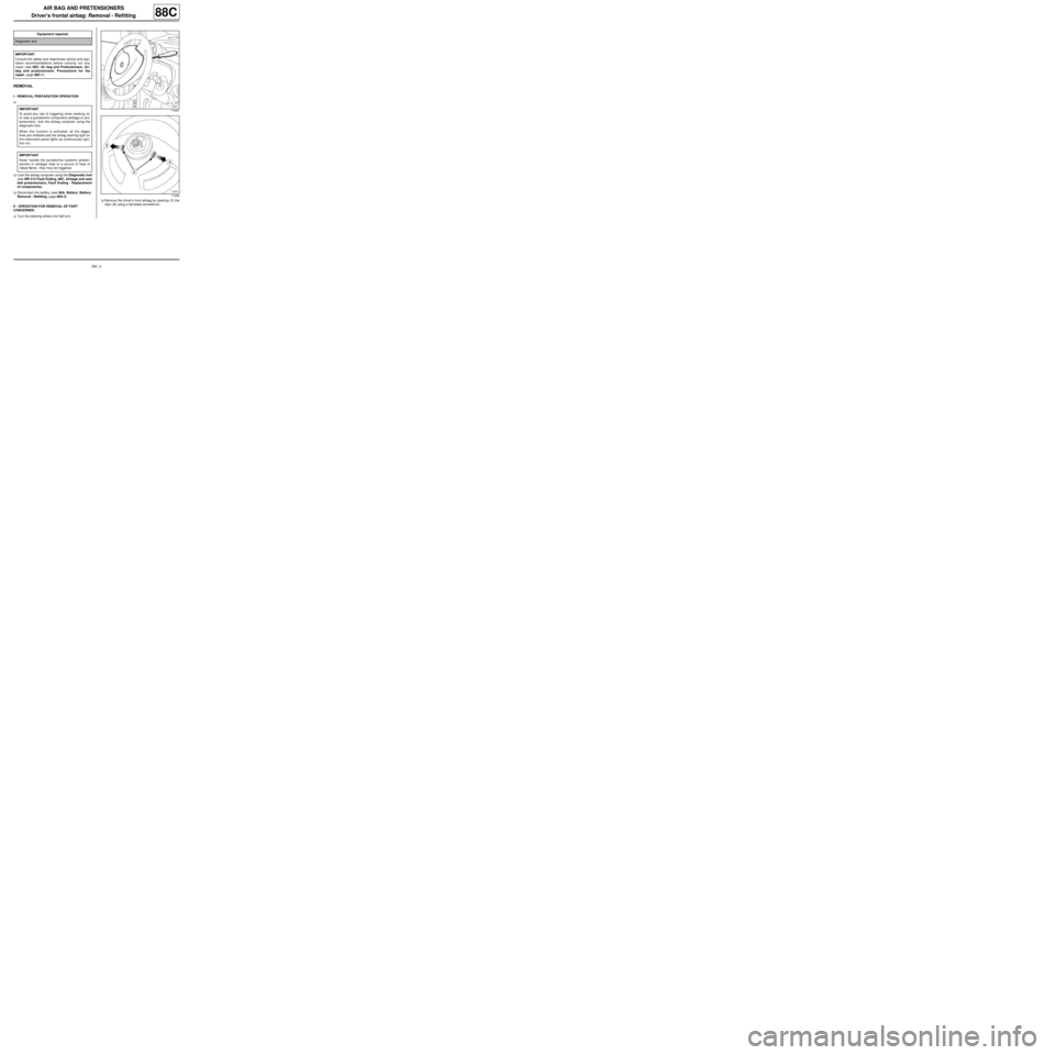
aTurn the steering wheel one half-turn.aRemove the driver's front airbag by opening (1) the
clips (2) using a flat-blade screwdriver. Equipment required
Diagnostic tool
IMPORTANT
Consult the safety and cleanliness advice and ope-
ration recommendations before carrying out any
repair (see 88C, Air bag and Pretensioners, Air-
bag and pretensioners: Precautions for the
repair, page 88C-1) .
IMPORTANT
To avoid any risk of triggering when working on
or near a pyrotechnic component (airbags or pre-
tensioners), lock the airbag computer using the
diagnostic tool.
When this function is activated, all the trigger
lines are inhibited and the airbag warning light on
the instrument panel lights up continuously (igni-
tion on).
IMPORTANT
Never handle the pyrotechnic systems (preten-
sioners or airbags) near to a source of heat or
naked flame - they may be triggered.
119481
119496