oil RENAULT TWINGO RS 2009 2.G Electrical Equipment Workshop Manual
[x] Cancel search | Manufacturer: RENAULT, Model Year: 2009, Model line: TWINGO RS, Model: RENAULT TWINGO RS 2009 2.GPages: 241
Page 153 of 241
88A-17
WIRING HARNESS
Engine wiring: Removal - Refitting
K9K
88A
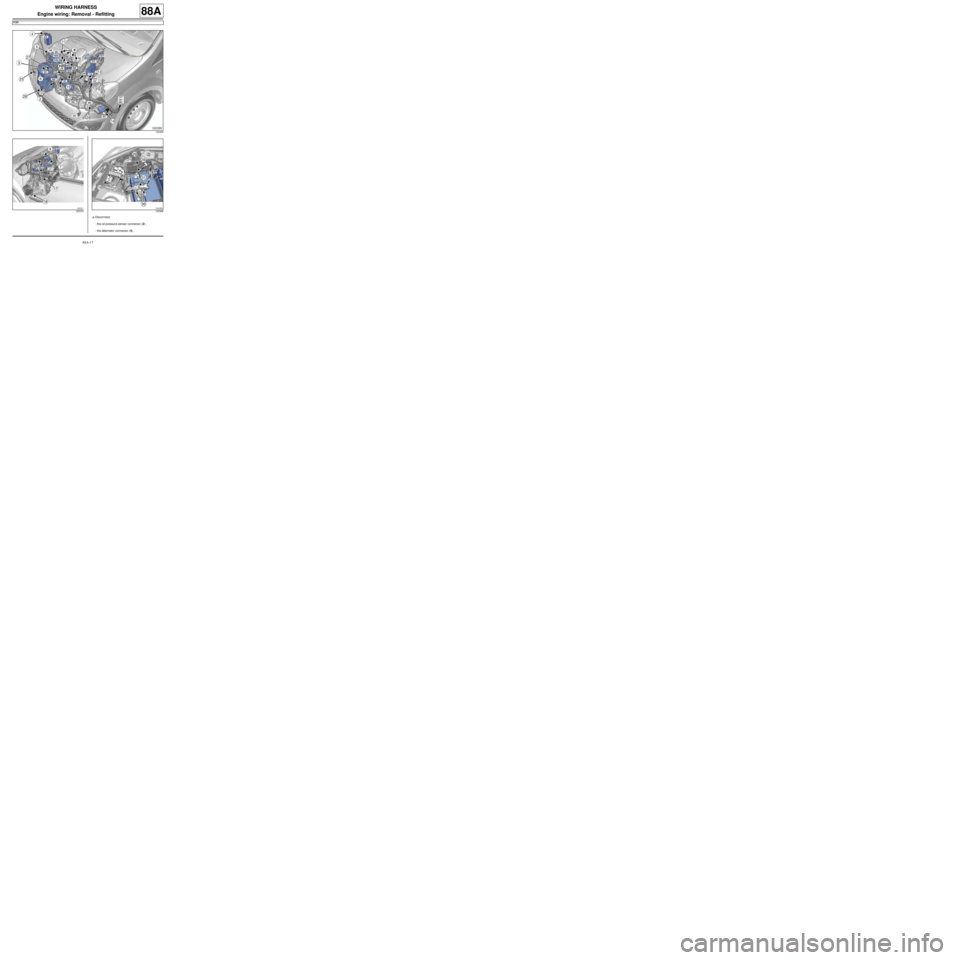
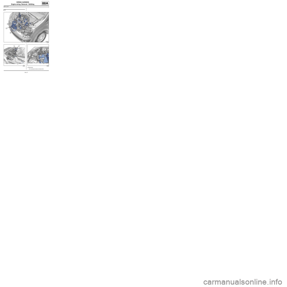
aDisconnect:
-the oil pressure sensor connector (2) ,
-the alternator connector (3) ,
122369
122370122368
Page 155 of 241
88A-19
WIRING HARNESS
Engine wiring: Removal - Refitting
K9K
88A
-the section of wiring on the cylinder block and sub-
frame,
-the section of wiring on the engine cooling fan as-
sembly.
aRemove the engine harness.
REFITTING
I - REFITTING PREPARATIONS OPERATION
aIf replacing with a complete wiring harness, lock the
unused connectors (see Connectors: Sealing and
locking) (Technical Note 6015A, 88A, Wiring).
II - REFITTING OPERATION FOR PART
CONCERNED
aRefit the engine harness.
aConnect the engine cooling fan assembly connector.
aConnect:
-the air conditioning compressor connector,
-the refrigerant fluid pressure sensor connector,
-the engine cooling fan assembly resistor connec-
tor,
-the engine cooling fan assembly connector.
aConnect:
-the engine harness/front of engine wiring connec-
tor,
-the reversing lights switch connector,
-the crankshaft position sensor connector,
-the coolant temperature sensor connector,
-the air inlet temperature sensor connector,-the exhaust gas recirculation solenoid valve con-
nector,
-the connector to the pre-postheating unit,
-the diesel injection computer connectors,
-the fuel rail pressure sensor connector,
-the fuel temperature sensor connector,
-the heater plugs connector,
-the injector connectors,
-the air temperature sensor connector,
-the turbocharging pressure sensor connector,
-the pinking sensor connector,
-the camshaft position sensor connector,
-the connector from the water detection sensor on
the fuel filter,
-the alternator connector,
-the oil pressure sensor connector.
aRefit:
-the engine compartment connection unit supply wi-
ring nut,
-the wiring mounting nut on the battery protection
fuse board,
-the battery protection fuse wiring nuts,
-the earth wiring nut on the front left-hand side
member,
-the positive battery terminal wiring nut,
-the engine earth wiring nut,
-the starter supply and earth terminal nuts,
-the alternator earth wiring nut.
aClip:
-the section of wiring on the cylinder head,
-the section of wiring on the cylinder block and sub-
frame,
-the section of wiring on the engine cooling fan as-
sembly.
III - FINAL OPERATION.
aRefit:
-the battery tray (see 80A, Battery, Battery tray:
Removal - Refitting, page 80A-6) ,
-the air filter unit (see Air filter unit: Removal - Re-
fitting) (MR 411, 12A, Fuel mixture), WARNING
To prevent any damage during the removal ope-
ration, check that the wiring is free from its moun-
tings (retaining clip, plastic clip, adhesive tape,
connector, etc.).
STANDARD HEATING
AIR CONDITIONING
Page 159 of 241
88A-23
WIRING HARNESS
Engine wiring: Removal - Refitting
D4F, and 780
88A
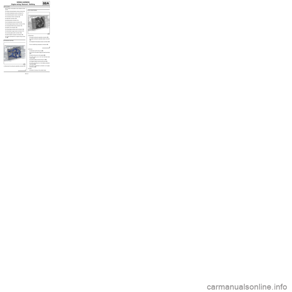
-the oil vapour recirculation hose reheater connec-
tor (5) ,
-the engine harness/injection wiring connector (6) ,
-the coolant temperature sensor connector (7) ,
-the crankshaft position sensor connector (8) ,
-the oil pressure sensor connector (9) ,
-the alternator connector (10) ,
-the pinking sensor connector (11) ,
-the air temperature sensor connector (12) ,
-the turbocharger pressure sensor connector (13) ,
-the motorised throttle valve connector (14) ,
-the ignition coil connector (15) ,
-the turbocharger solenoid valve connector (16) ,
-the downstream oxygen sensor connector (17) ,
-the reversing lights switch connector (18) ,
-the petrol injection computer connectors (19) ,
-the engine harness/front of engine wiring connec-
tor (20) .
aDisconnect the cooling fan assembly connector (21)
.aDisconnect:
-the engine cooling fan assembly connector (22) ,
-the engine cooling fan assembly resistor connector
(23) .
-the refrigerant fluid pressure sensor connector (24)
,
-the air conditioning compressor connector (25) ,
aRemove:
-the alternator earth wiring nut (26) ,
-the nuts from the starter supply and earth terminals
(27) ,
-the earth wiring nuts on the engine (28) ,
-the earth wiring nut on the front left-hand side
member (29) ,
-the positive battery terminal wiring nut (30) ,
-the negative battery terminal wiring nuts (31) ,
-the wiring mounting nut on the battery protection
fuse board (33) ,
-the engine compartment connection unit supply
terminal nut (32) .
aUnclip:
-the section of wiring on the cylinder head, STANDARD HEATING
122359
AIR CONDITIONING
125249
Page 160 of 241
88A-24
WIRING HARNESS
Engine wiring: Removal - Refitting
D4F, and 780
88A
-the section of wiring on the cylinder block and sub-
frame,
-the section of wiring on the engine cooling fan as-
sembly.
aRemove the engine harness.
REFITTING
I - REFITTING PREPARATION OPERATION
aIf replacing with a complete wiring harness, lock the
unused connectors (see Connectors: Sealing and
locking) (Technical Note 6015A, 88A, Wiring).
II - REFITTING OPERATION FOR PART
CONCERNED
aRefit the engine harness.
aConnect the engine cooling fan assembly connector.
aConnect:
-the air conditioning compressor connector,
-the refrigerant fluid pressure sensor connector,
-the engine cooling fan assembly connector,
-the engine cooling fan assembly resistor connec-
tor.
aConnect:
-the engine harness/front of engine wiring connec-
tor,
-the connectors to the petrol injection computer,
-the reversing lights switch connector,
-the downstream oxygen sensor connector,
-the turbocharger solenoid valve connector,-the ignition coil connector,
-the motorised throttle valve connector,
-the turbocharger pressure sensor connector,
-the air temperature sensor connector,
-the pinking sensor connector,
-the alternator connector,
-the oil pressure sensor connector,
-the crankshaft position sensor connector,
-the coolant temperature sensor connector,
-the engine harness/injection wiring connector,
-the oil vapour recirculation hose reheater connec-
tor,
-the air inlet pressure sensor connector,
-upstream oxygen sensor connector,
-the fuel vapour absorber connector.
aRefit:
-the engine compartment connection unit supply
terminal nut,
-the wiring mounting nut on the battery protection
fuse board,
-the negative battery terminal wiring nuts,
-the positive battery terminal wiring nut,
-the earth wiring nut on the front left-hand side
member,
-the earth wiring nuts on the engine,
-the starter wiring nuts,
-the alternator earth wiring nut.
aClip:
-the section of wiring on the cylinder head,
-the section of wiring on the cylinder block and sub-
frame,
-the section of wiring on the engine cooling fan as-
sembly.
III - FINAL OPERATION.
aRefit:
-the battery tray (see 80A, Battery, Battery tray:
Removal - Refitting, page 80A-6) ,
-the air filter unit (see Air filter unit: Removal - Re-
fitting) (MR 411, 12A, Fuel mixture),
-the battery (see 80A, Battery, Battery: Removal -
Refitting, page 80A-2) , WARNING
To prevent any damage during the removal ope-
ration, check that the wiring is free from its moun-
tings (retaining clip, plastic clip, adhesive tape,
connector, etc.).
STANDARD HEATING
AIR CONDITIONING
Page 163 of 241
88A-27
WIRING HARNESS
Engine wiring: Removal - Refitting
D4F or D7F
88A
aDisconnect:
-the oil pressure sensor connector (2) , D7F
122366
122367122368
Page 164 of 241
88A-28
WIRING HARNESS
Engine wiring: Removal - Refitting
D4F or D7F
88A
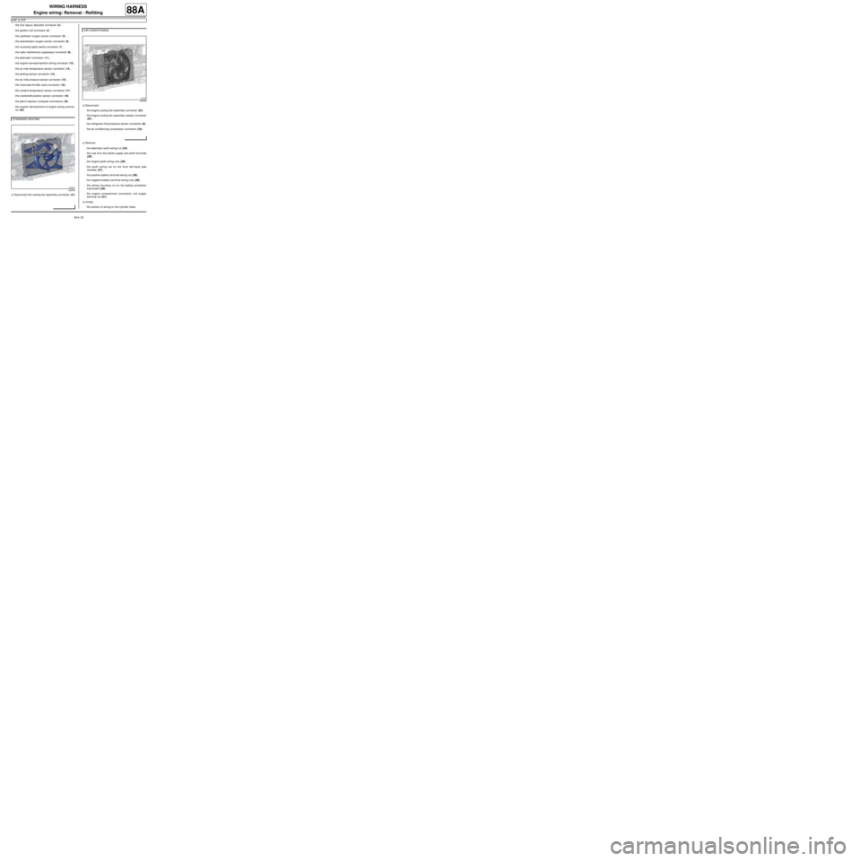
-the fuel vapour absorber connector (3) ,
-the ignition coil connector (4) ,
-the upstream oxygen sensor connector (5) ,
-the downstream oxygen sensor connector (6) ,
-the reversing lights switch connector (7) ,
-the radio interference suppressor connector (8) ,
-the alternator connector (11) ,
-the engine harness/injection wiring connector (12) ,
-the air inlet temperature sensor connector (13) ,
-the pinking sensor connector (14) ,
-the air inlet pressure sensor connector (15) ,
-the motorised throttle valve connector (16) ,
-the coolant temperature sensor connector (17) ,
-the crankshaft position sensor connector (18)
-the petrol injection computer connectors (19) ,
-the engine harness/front of engine wiring connec-
tor (20) .
aDisconnect the cooling fan assembly connector (21)
.aDisconnect:
-the engine cooling fan assembly connector (22) ,
-the engine cooling fan assembly resistor connector
(23) ,
-the refrigerant fluid pressure sensor connector (9) ,
-the air conditioning compressor connector (10) .
aRemove:
-the alternator earth wiring nut (24) ,
-the nuts from the starter supply and earth terminals
(25) ,
-the engine earth wiring nuts (26) ,
-the earth wiring nut on the front left-hand side
member (27) ,
-the positive battery terminal wiring nut (28) ,
-the negative battery terminal wiring nuts (29) ,
-the wiring mounting nut on the battery protection
fuse board (30) ,
-the engine compartment connection unit supply
terminal nut (31) .
aUnclip:
-the section of wiring on the cylinder head, STANDARD HEATING
122359
AIR CONDITIONING
125249
Page 167 of 241
88A-31
WIRING HARNESS
Engine wiring: Removal - Refitting
D4F or D7F
88A
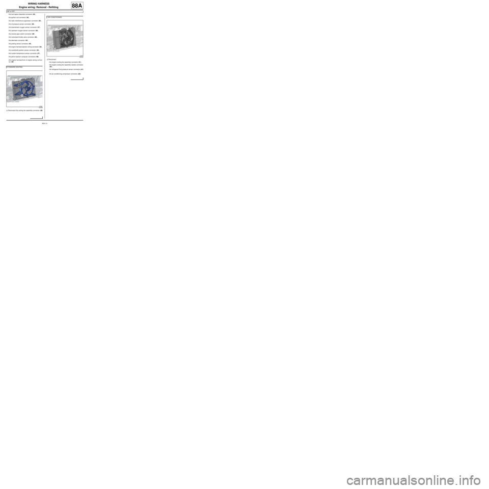
-the fuel vapour absorber connector (33) ,
-the ignition coil connector (34) ,
-the radio interference suppressor connector (35) ,
-the oil pressure sensor connector (36) ,
-the downstream oxygen sensor connector (37) ,
-the upstream oxygen sensor connector (38) ,
-the reverse gear switch connector (39) ,
-the motorised throttle valve connector (40) ,
-the alternator connector (43) ,
-the pinking sensor connector (44) ,
-the engine harness/injection wiring connector (45) ,
-the crankshaft position sensor connector (46) ,
-the coolant temperature sensor connector (47) ,
-the petrol injection computer connectors (48) ,
-the engine harness/front of engine wiring connec-
tor (49) .
aDisconnect the cooling fan assembly connector (50)
.aDisconnect:
-the engine cooling fan assembly connector (51) ,
-the engine cooling fan assembly resistor connector
(52) ,
-the refrigerant fluid pressure sensor connector (41)
,
-the air conditioning compressor connector (42) . STANDARD HEATING
122359
AIR CONDITIONING
125249
Page 169 of 241
88A-33
WIRING HARNESS
Engine wiring: Removal - Refitting
D4F or D7F
88A
-the section of wiring on the cylinder block and sub-
frame,
-the section of wiring on the engine cooling fan as-
sembly.
aRemove the engine harness.
REFITTING
I - REFITTING PREPARATIONS OPERATION
aIf replacing with a complete wiring harness, lock the
unused connectors (see Connectors: Sealing and
locking) (Technical Note 6015A, 88A, Wiring).
II - REFITTING OPERATION FOR PART
CONCERNED
aRefit the engine harness.
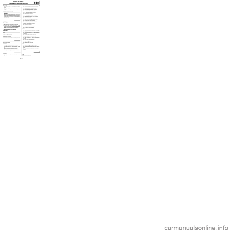
aConnect the engine cooling fan assembly connector.
aConnect:
-the engine cooling fan assembly connector,
-the engine cooling fan assembly resistor connec-
tor,
-the air conditioning compressor connector,
-the refrigerant fluid pressure sensor connector.
aConnect:
-the engine harness/front of engine wiring connec-
tor,-the connectors to the petrol injection computer,
-the crankshaft position sensor connector,
-the coolant temperature sensor connector,
-the motorised throttle valve connector,
-the air inlet pressure sensor connector,
-the pinking sensor connector,
-the air inlet temperature sensor connector,
-the engine harness/injection wiring connector,
-the alternator connector,
-the radio interference suppressor connector,
-the reversing lights switch connector,
-the downstream oxygen sensor connector,
-upstream oxygen sensor connector,
-the ignition coil connector,
-the fuel vapour absorber connector,
-the oil pressure sensor connector.
aRefit:
-the engine compartment connection unit supply
terminal nut,
-the wiring mounting nut on the battery protection
fuse board,
-the negative battery terminal wiring nuts,
-the positive battery terminal wiring nut,
-the earth wiring nut on the front left-hand side
member,
-the earth wiring nuts on the engine,
-the starter wiring nuts,
-the alternator earth wiring nut.
aClip:
-the section of wiring on the cylinder head,
-the section of wiring on the cylinder block and sub-
frame,
-the section of wiring on the engine cooling fan as-
sembly.
aRefit the engine harness. WARNING
To prevent any damage during the removal ope-
ration, check that the wiring is free from its moun-
tings (retaining clip, plastic clip, adhesive tape,
connector, etc.).
D7F
STANDARD HEATING
AIR CONDITIONING
D4F
Page 170 of 241
88A-34
WIRING HARNESS
Engine wiring: Removal - Refitting
D4F or D7F
88A
aConnect:
-the engine harness/sequential gearbox wiring con-
nector,
-the sequential gearbox computer connectors.
aConnect the engine cooling fan assembly connector.
aConnect:
-the engine cooling fan assembly connector,
-the engine cooling fan assembly resistor connec-
tor,
-the air conditioning compressor connector,
-the refrigerant fluid pressure sensor connector.aConnect:
-the engine harness/front of engine wiring connec-
tor,
-the connectors to the petrol injection computer,
-the coolant temperature sensor connector,
-the crankshaft position sensor connector,
-the engine harness/injection wiring connector,
-the pinking sensor connector,
-the alternator connector,
-the motorised throttle valve connector,
-the reverse gear switch connector,
-upstream oxygen sensor connector,
-the downstream oxygen sensor connector,
-the oil pressure sensor connector,
-the radio interference suppressor connector,
-the ignition coil connector,
-the fuel vapour absorber connector,
-the air inlet pressure sensor connector.
aRefit:
-the engine compartment connection unit supply
terminal nut,
-the wiring mounting nut on the battery protection
fuse board,
-the negative battery terminal wiring nuts,
-the positive battery terminal wiring nut,
-the earth wiring nut on the front left-hand side
member,
-the earth wiring nuts on the engine,
-the starter wiring nuts,
-the alternator earth wiring nut.
aClip:
-the section of wiring on the cylinder head,
-the section of wiring on the cylinder block and sub-
frame,
-the section of wiring on the engine cooling fan as-
sembly. JH1
STANDARD HEATING
AIR CONDITIONING
Page 174 of 241
88A-38
WIRING HARNESS
Engine wiring: Removal - Refitting
EQ UIPMENT LEVEL SPORT
88A
-the air temperature sensor (5) ,
-the coolant circuit pressure sensor (6) ,
-the alternator (7) ,
-the air conditioning compressor (8) ,
-the upstream oxygen sensor (9) ,
-the pinking sensor (10) ,
-the oil pressure sensor (11) ,
-the ignition coils (12) ,
-the engine wiring/injection wiring connector (R37)
(13) ,
-the coolant temperature sensor (14) ,
-the petrol injection computer (15) ,
-the engine fuse and relay box (16) ,
-the cooling fan assembly (17) ,
-the air conditioning fan assembly resistors (18) .
a
aRemove:
-the starter supply terminal nuts (19) ,
-the wiring nut on the alternator (20) ,
-the earth cable nuts on the front left-hand side
member (21) ,
-the earth cable bolt on the gearbox (22) ,
-the bolts of the engine wiring channel (23) ,
-the engine wiring support nut on the left-hand sus-
pended engine mounting (24) .
aUnclip:
-the distribution unit wiring section,
-the gearbox wiring section.aDisconnect the connectors from:
-the throttle valve (25) ,
-the downstream oxygen sensor (26) ,
-the crankshaft position sensor (27) ,
-the air inlet pressure sensor (28) ,
-the fuel vapour absorber bleed solenoid valve (29) ,
-the reverse gear switch (30) . Note:
Before removing the earth terminal, mark its
position using a indelible pencil by drawing a
line on the earth terminal and on the gearbox
housing.
When reassembling, improper positioning of the
earth ter minal on the gearbox casing could result
in damage to the earth terminal or earth wiring.
140656