fuse RENAULT TWINGO RS 2009 2.G Engine And Peripherals Passenger Compartment Connection Unit OBD User Guide
[x] Cancel search | Manufacturer: RENAULT, Model Year: 2009, Model line: TWINGO RS, Model: RENAULT TWINGO RS 2009 2.GPages: 179, PDF Size: 0.57 MB
Page 39 of 179
87B-39
MR-413-X44-87B000$384.mif
V5
PASSENGER COMPARTMENT CONNECTION UNIT
Fault finding - Interpretation of faults
UCH
Vdiag No.: 44
87B
DF062
PRESENT
OR
STOREDSTARTER RELAY CONTROL CIRCUIT
CC.1 : Short circuit to + 12 volts
NOTESConditions for applying the fault finding procedure to stored faults:
The fault is declared present after the starter is activated.
WARNING
When activating the starter, none of the gears must be engaged
(and the parking brake must be applied).
Check that fuse F9 (15 A) is sound and correctly fitted in the passenger compartment fuse and relay box
(component code 1016) and relay A (20 A) in the engine fuse and relay box (component code 597).
Replace the fuse if necessary.
Check the condition and connection of the UCH 24-track connector PE1 (component code 645) (tabs bent,
oxidised or broken).
Check the condition and connection of the starter relay 4-track black connector (tabs bent, oxidised or broken).
With the starter activated, check for + 12 V on connection 1B of component 645.
With the starter activated, check for + 12 V on connection AP29 of component 232.
Check the insulation, continuity and absence of interference resistance of the following connections:
Starter relay check:
●Connection code 1B between components 232 and 645.
●Connection code 1A between components 232 and 163.
●Connection code D between components 232 and 104.
●Connection code AP23 between components 232 and 1016.
If the connection or connections are faulty and there is a repair procedure (see Technical Note 6015A, Electrical
wiring repair, Wiring: Precautions for repair), repair the wiring, otherwise replace it.
If the connections are correct, replace the starter relay (component code 232). (See MR 411 Mechanical
systems 16A, Starting - Charging, Starting system: Identification).
If the connections and the relay are correct, check the starter (component code 163). (See MR 411 Mechanical
systems 16A, Starting - Charging, Starting system: Identification).
If the fault is still present, contact the Techline.
AFTER REPAIRCarry out another fault finding check on the system.
Clear the stored faults.
Deal with any other faults.
UCH_V44_DF062
Page 40 of 179
87B-40
MR-413-X44-87B000$384.mif
V5
PASSENGER COMPARTMENT CONNECTION UNIT
Fault finding - Interpretation of faults
UCH
Vdiag No.: 44
87B
* SR: SunroofDF065
PRESENT
OR
STORED
ELECTRIC WINDOWS AUTHORISATION CONNECTION
CC.1 : Short circuit to + 12 volts
NOTESConditions for applying fault finding procedures to stored faults:
The fault is declared present after:
The ignition is switched of f and back on again after pressing the driver's one-touch
electric window switch or sunroof switch if the vehicle is fitted with a sunroof.
For vehicles fitted with sunroof (component code 1578):
Check that the vehicle is configured with One-touch window(s) S.R*. :
Check that LC070 One-touch window(s) S.R. is With. Otherwise use CF173
One-touch window(s) S.R.
Check the condition and connection of the UCH 24-track connector PE2 (component code 645) (tabs bent,
oxidised or broken).
Check the condition and connection of the driver's electric window motor 6-track connector (bent, oxidised,
broken tabs).
If there is an electric sunroof, check that fuse F26 (20 A) is sound and correctly fitted in the passenger
compartment fuse and relay box (component 1016).
Replace the fuse if necessary.
If there is an electric sunroof, check the condition and connection of the A-pillar 4-track connector 339 and of
sunroof computer connector AA (tabs bent, oxidised, broken).
Check the insulation, continuity and absence of interference resistance of the following connections:
●Connection code 21K between components 203 and 645.
●Connection code MAM between component 203 and earth MAM.
For vehicles fitted with a sunroof:
●Connection code 21K between components 1579 and 645.
●Connection code MAM between component 1579 and earth MAM.
If the connection or connections are faulty and there is a repair procedure (see Technical Note 6015A, Electrical
wiring repair, Wiring: Precautions for repair), repair the wiring, otherwise replace it.
If the fault is still present, switch on the ignition and check for 0 V on connection 21K if no (see 87D
electric windows - Sunroof).
AFTER REPAIRCarry out another fault finding check on the system.
Clear the stored faults.
Deal with any other faults.
UCH_V44_DF065
Page 41 of 179
87B-41
MR-413-X44-87B000$384.mif
V5
PASSENGER COMPARTMENT CONNECTION UNIT
Fault finding - Interpretation of faults
UCH
Vdiag No.: 44
87B
*CPE: Electric central door locking.DF082
PRESENT
OR
STORED
DOOR LOCKING BUTTON CIRCUIT
CC.0 : Short circuit to earth
NOTESConditions for applying fault finding procedures to stored faults:
The fault appears after:
Pressing the central door locking button.
OR
Running AC020 CPE* button indicator light.
Check that the vehicle is correctly configured:
Check that LC003 Deadlocking is With. Otherwise carry out CF009 Deadlocking.
Check that LC040 Automatic locking when driving is With. Otherwise carry out CF108 Automatic locking
when driving.
Check that LC093 Central door locking is With. Otherwise perform CF192 Central door locking.
Check that the door locking button indicator light comes on when running command AC020 CPE button
indicator light.
Check that fuses F42 (10 A) and F46 (15 A) on component 1016 are sound and correctly fitted.
Check the condition and connection of the door lock switch/hazard warning lights switch connector (component
code 1391) (bent, oxidised, broken tabs).
Check the condition and connection of the UCH 40-track connector PE2 (component code 645) (tabs bent,
oxidised or broken).
Check for + 12 V on the following connections:
●Connection code 20M between components 1391 and 645.
●Connection code 20AW between components 1391 and 645.
If the connection or connections are faulty and there is a repair procedure (see Technical Note 6015A, Electrical
wiring repair, Wiring: Precautions for repair), repair the wiring, otherwise replace it.
Check the insulation, continuity and the absence of interference resistance on the connections between:
●Connection code 20M between components 1391 and 645.
●Connection code 20AW between components 1391 and 645.
If the connection or connections are faulty and there is a repair procedure (see Technical Note 6015A, Electrical
wiring repair, Wiring: Precautions for repair), repair the wiring, otherwise replace it.
If the fault is still present, replace the central door locking/hazard warning lights switch (component code 1391).
(See MR 411 Mechanical systems 84A, Controls - Signals, Hazard warning lights and central door locking:
Removal - Refitting).
If the fault is still present, contact the Techline.
AFTER REPAIRCarry out another fault finding check on the system.
Clear the stored faults.
Deal with any other faults.
UCH_V44_DF082
Page 42 of 179
87B-42
MR-413-X44-87B000$384.mif
V5
PASSENGER COMPARTMENT CONNECTION UNIT
Fault finding - Interpretation of faults
UCH
Vdiag No.: 44
87B
With automatic headlighting:DF087
PRESENT
OR
STORED
SIDE LIGHTS RELAY CONTROL CIRCUIT
CC.1 : Short circuit to + 12 volts
CC.0 : Open circuit or short circuit to earth
NOTESConditions for applying the fault finding procedure to stored faults:
The fault reappears after:
The ignition is switched on and the side lights are activated.
OR
Running AC055 Side lights
Note:
This fault only appears on vehicles fitted with automatic headlighting.
Check for the rain/light sensor (component code 1415) then use the diagnostic tool
to check:
–Check that LC044 "Rain/light sensor" displays "Present". If not, carry out
CF035 "Rain/light sensor".
–Check that LC095 "Automatic headlight function", displays "With". If not, carry
out CF193 "Automatic headlight function".
–Check that LC096 "Automatic wiper function" displays "With". If not, carry out
CF194 "Automatic headlight function".
Check that fuses F14 (20 A), F15 (5 A), F25 (5 A), F39 (10 A), F40 (5 A), F42 (10 A) and F43 (10 A) are sound
and correctly fitted in the passenger compartment fuse and relay box (component code 1016).
Replace the fuse(s) if necessary.
Check the presence and condition of the side light relays (component code 289) (20A) and 1034 (20A).
Replace the side light relay (component code 289) if necessary.
Check the condition and connection of the light concerned (bent, oxidised, broken tabs).
Check the condition and connection of the 40-track connectors PE1 and PE2 of the UCH (component code 645)
(tabs broken, bent or oxidised).
Check the condition and connection of the horn and lights switch connector (component code 209) (tabs bent,
oxidised, broken).
Check for the + 12 V (when requesting the side lights) on connection LPD of component 184 and on
connection LPG of component 185. Check for the earth on connection MAR of component 184 and on
connection MAS of component 185.
If the connection or connections are faulty and there is a repair procedure (see Technical Note 6015A, Electrical
wiring repair, Wiring: Precautions for repair), repair the wiring, otherwise replace it.
AFTER REPAIRCarry out another fault finding check on the system.
Clear the stored faults.
Deal with any other faults.
UCH_V44_DF087
Page 44 of 179
87B-44
MR-413-X44-87B000$384.mif
V5
PASSENGER COMPARTMENT CONNECTION UNIT
Fault finding - Interpretation of faults
UCH
Vdiag No.: 44
87B
DF087
CONTINUED 2
Checking the monolever (component code 209):
Check the insulation, continuity and the absence of interference resistance on the following connections:
Check between the monolever (component code 209) and the UCH:
●Connection code 78B between components 645 and 209.
Check between the monolever (component code 209) and the passenger compartment fuse and relay box
(component code 1016):
●Connection code BPA2 between components 1016 and 209.
●Connection code BPA3 between components 1016 and 209.
●Connection code BPA4 between components 1016 and 209.
●Connection code MAN or MAM between component 209 and earth MAN or MAM (depending on the driving
layout, right- or left-hand drive).
Check for + 12 V on connections BPA2 and BPA3 of component 209. Check for earth on connection MAM
(for right-hand drive vehicles) or MAN (for left-hand drive vehicles) of component 209.
If the connection or connections are faulty and there is a repair procedure (see Technical Note 6015A, Electrical
wiring repair, Wiring: Precautions for repair), repair the wiring, otherwise replace it.
If the feeds, earth and connections are correct, replace the monolever (component code 209). (See MR 411
Mechanical systems 84A, Controls - Signals, Lighting and signals switch:
Removal - Refitting)
If the fault is still present, contact the Techline.
AFTER REPAIRCarry out another fault finding check on the system.
Clear the stored faults.
Deal with any other faults.
Page 45 of 179
87B-45
MR-413-X44-87B000$384.mif
V5
PASSENGER COMPARTMENT CONNECTION UNIT
Fault finding - Interpretation of faults
UCH
Vdiag No.: 44
87B
With automatic headlighting:DF088
PRESENT
OR
STORED
DIPPED BEAM HEADLIGHTS RELAY CONTROL CIRCUIT
CC.1 : Short circuit to + 12 volts
CC.0 : Open circuit or short circuit to earth
NOTESConditions for applying the fault finding procedure to stored faults:
The fault reappears after:
The ignition is switched on and the side lights are activated.
OR
Running AC054 Dipped headlights
Note:
This fault only appears on vehicles fitted with automatic headlighting.
Check for the rain/light sensor (component code 1415) then:
–Check that the vehicle has a rain/light sensor (component code 1415).
–Check that LC044 "Rain/light sensor" displays "Present". If not, carry out
CF035 "Rain/light sensor".
–Check that LC096 "Automatic wiper function" displays "With". If not, carry out
CF194 "Automatic wiper function".
–Check that LC095 "Automatic headlight function", displays "With". If not, carry
out CF193 "Automatic headlight function".
Check that fuses F13 (30A), F15 (5A), F25 (5 A), F34 (15 A) and F35 (15 A) are sound and correctly fitted in the
passenger compartment fuse and relay box (component code 1016).
Replace the fuse if necessary.
Check the presence and condition of the dipped headlights relay (component code 281) (20A).
Replace the dipped headlights relay (component code 281) if necessary.
Check the correct positioning and condition of the bulb concerned.
Replace the light if necessary.
Check the condition and connection of the light concerned (bent, oxidised, broken tabs).
Check the condition and connection of the UCH 40-track connector PE2 (component code 645) (tabs bent,
oxidised or broken).
Check the condition and connection of the horn and lights switch connector (component code 209) (tabs bent,
oxidised, broken).
If the connector is faulty and there is a repair method (see Technical Note 6015A, Repairing electrical wiring,
Wiring: Precautions for repair), repair the wiring, otherwise replace the wiring.
AFTER REPAIRCarry out another fault finding check on the system.
Clear the stored faults.
Deal with any other faults.
UCH_V44_DF088
Page 47 of 179
87B-47
MR-413-X44-87B000$384.mif
V5
PASSENGER COMPARTMENT CONNECTION UNIT
Fault finding - Interpretation of faults
UCH
Vdiag No.: 44
87B
DF088
CONTINUED 2
Checking the monolever (component code 209):
Check the insulation, continuity and the absence of interference resistance on the following connections:
Check between the monolever (component code 209) and the UCH:
●Connection code 78Q between components 645 and 209.
Check between the monolever (component code 209) and the passenger compartment fuse and relay box
(component code 1016):
●Connection code BPA3 between components 1016 and 209.
●Connection code MAN or MAM between component 209 and earth MAN or earth MAM (depending on the
driving layout, right- or left-hand drive).
If the connection or connections are faulty and there is a repair procedure (see Technical Note 6015A, Electrical
wiring repair, Wiring: Precautions for repair), repair the wiring, otherwise replace it.
Check for + 12 V on connections BPA2 and BPA3 of component 209.
Check for earth on connection MAM (for right-hand drive vehicles) or MAN (for left-hand drive vehicles) of
component 209.
If the connection or connections are faulty and there is a repair procedure (see Technical Note 6015A, Electrical
wiring repair, Wiring: Precautions for repair), repair the wiring, otherwise replace it.
If the feeds, earth and connections are correct, replace the monolever (component code 209). (See MR 411
Mechanical systems 84A, Controls - Signals, Lighting and signals switch:
Removal - Refitting)
If the fault is still present, contact the Techline.
AFTER REPAIRCarry out another fault finding check on the system.
Clear the stored faults.
Deal with any other faults.
Page 48 of 179
87B-48
MR-413-X44-87B000$384.mif
V5
PASSENGER COMPARTMENT CONNECTION UNIT
Fault finding - Interpretation of faults
UCH
Vdiag No.: 44
87B
DF097
PRESENT
OR
STOREDWINDSCREEN WIPER PARK POSITION CIRCUIT
1.DEF : Open circuit or short circuit to earth
NOTESConditions for applying the fault finding procedure to stored faults:
The fault is declared present after the ignition is switched off and back on and the front
wipers are operated from the wiping stalk.
This fault may appear if the windscreen wiper motor is forced (e.g.: used on a dry screen, snow on the screen,
etc.).
Check that fuse F2 (15 A) is sound and correctly fitted to the passenger compartment fuse and relay box
(component code 1016).
Replace the fuse if necessary.
Check the condition and connection of the 5-track windscreen wiper motor connector (OR) (component code
212) (broken, bent, oxidised tabs).
Check the condition and connection of the 40-track connectors PE1, PE2 and PE3 of the UCH (component
code 645) (tabs broken, bent or oxidised).
Check that the earth on connection MAS of the windscreen wiper motor connector (component code 212) is
correct.
If the connection is faulty and there is a repair procedure (see Technical Note 6015A, Electrical wiring repair,
Wiring: Precautions for repair), repair the wiring, otherwise replace it.
Activate low speed, check for + 12 V on connections 14B of the windscreen wiper motor
connector (component code 212). Activate the high speed, check for + 12 V on connection 14A of the
windscreen wiper motor connector (component code 212).
If there is no + 12 V, check the insulation, continuity and the absence of interference resistance on the
following connections:
Check the combined wiper-washer:
●Connection code AP71 between components 145 and 1016.
●Connection code 14E (windscreen wiper timed control) between components 645 and 145.
●Connection code 14G (low speed windscreen wiper control) between components 645 and 145.
●Connection code 14H (high speed windscreen wiper control) between components 645 and 145.
●Connection code MAN (left-hand drive or MAN (right-hand drive) between component 145 and the earth
MAN (left-hand drive) or MAM (right-hand drive).
AFTER REPAIRCarry out another fault finding check on the system.
Clear the stored faults.
Deal with any other faults.
UCH_V44_DF097
Page 50 of 179
87B-50
MR-413-X44-87B000$384.mif
V5
PASSENGER COMPARTMENT CONNECTION UNIT
Fault finding - Interpretation of faults
UCH
Vdiag No.: 44
87B
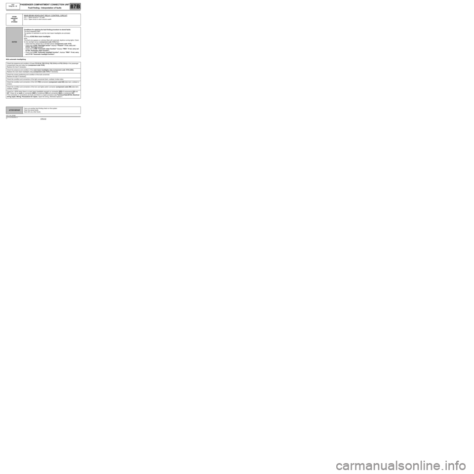
With automatic headlighting:DF098
PRESENT
OR
STORED
MAIN BEAM HEADLIGHT RELAY CONTROL CIRCUIT
CC.1 : Short circuit to + 12 volts
CC.0 : Open circuit or short circuit to earth
NOTESConditions for applying the fault finding procedure to stored faults:
The fault reappears after:
The ignition is switched on and the main beam headlights are activated.
OR
Running AC062 Main beam headlights
Note:
This fault only appears on vehicles fitted with automatic daytime running lights. Check
for the rain/light sensor (component code 1415) then:
–Check that the vehicle has a rain/light sensor (component code 1415).
–Check that LC044 "Rain/light sensor" displays "Present". If not, carry out -
CF035 "Rain/light sensor".
–Check that LC096 "Automatic wiper function" displays "With". If not, carry out
CF194 "Automatic wiper function".
–Check that LC095 "Automatic headlight function", displays "With". If not, carry
out CF193 "Automatic headlight function".
Check the presence and condition of fuses F15 (5 A), F25 (15 A), F32 (10 A) and F33 (10 A) on the passenger
compartment fuse and relay box (component code 1016).
Replace the fuse if necessary.
Check the presence and condition of the main beam headlights relay (component code 1574) (20A).
Replace the main beam headlights relay (component code 1574) if necessary.
Check the correct positioning and condition of the bulb concerned.
Replace the light if necessary.
Check the condition and connection of the light concerned (bent, oxidised, broken tabs).
Check the condition and connection of the UCH PE2 connectors (component code 645) (tabs bent, oxidised or
broken).
Check the condition and connection of the horn and lights switch connector (component code 209) (tabs bent,
oxidised, broken).
Check for + 12 V (when there is a main beam headlights request) on connection RPD of components 226 and
227. Check for an earth on connection MAR of component 226 and connection MAS on component 227.
If the connection or connections are faulty and there is a repair procedure (see Technical Note 6015A, Electrical
wiring repair, Wiring: Precautions for repair), repair the wiring, otherwise replace it.
AFTER REPAIRCarry out another fault finding check on the system.
Clear the stored faults.
Deal with any other faults.
UCH_V44_DF098
Page 51 of 179
87B-51
MR-413-X44-87B000$384.mif
V5
PASSENGER COMPARTMENT CONNECTION UNIT
Fault finding - Interpretation of faults
UCH
Vdiag No.: 44
87B
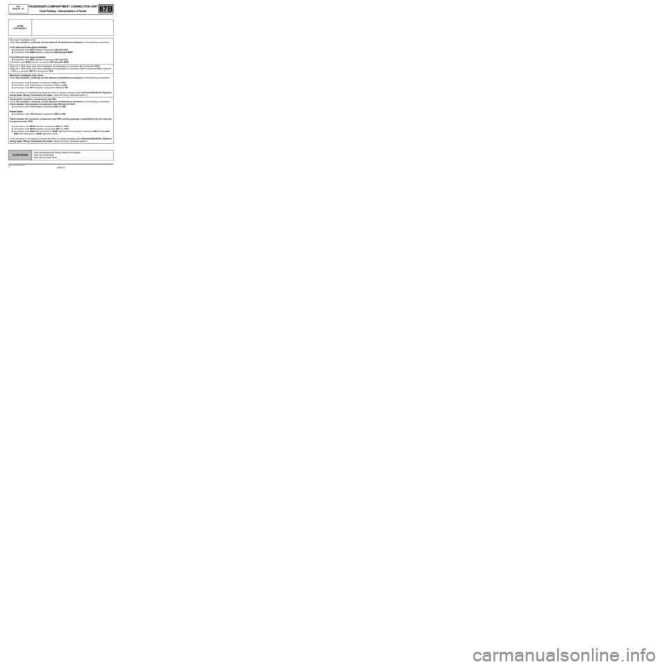
DF098
CONTINUED 1
Main beam headlights check:
Check the insulation, continuity and the absence of interference resistance on the following connections:
Front right-hand main beam headlight:
●Connection code RPD between components 226 and 1016.
●Connection code MAR between component 226 and earth MAR.
Front left-hand main beam headlight:
●Connection code RPG between components 227 and 1016.
Connection code MAS between component 227 and earth MAS.
Check for + 12 V (when main beam headlights are requested) on connection R of component 1574.
Check for + 12 V (when main beam headlights are requested) on connection 11A of component 1574. Check for
+ 12 V on connection BP11 of component 1574.
Main beam headlights relay check:
Check the insulation, continuity and the absence of interference resistance on the following connections:
●Connection code R between components 1016 and 1574.
●Connection code 11A between components 1574 and 645.
●Connection code BP11 between components 1574 and 597.
If the connection or connections are faulty and there is a repair procedure (see Technical Note 6015A, Electrical
wiring repair, Wiring: Precautions for repair), repair the wiring, otherwise replace it.
Checking the monolever (component code 209):
Check the insulation, continuity and the absence of interference resistance on the following connections:
Check between the monolever (component code 209) and the UCH:
●Connection code 11Q between components 645 and 209.
Hazard lights:
●Connection code 11R between components 209 and 654.
Check between the monolever (component code 209) and the passenger compartment fuse and relay box
(component code 1016):
●Connection code BPA2 between components 209 and 1016.
●Connection code BPA3 between components 209 and 1016.
●Connection code MAN (left-hand drive) or MAM (right-hand drive) between component 209 and the earth
MAN (left-hand drive) or MAM (right-hand drive).
If the connection or connections are faulty and there is a repair procedure (see Technical Note 6015A, Electrical
wiring repair, Wiring: Precautions for repair), repair the wiring, otherwise replace it.
AFTER REPAIRCarry out another fault finding check on the system.
Clear the stored faults.
Deal with any other faults.