fuse RENAULT TWINGO RS 2009 2.G Engine And Peripherals Passenger Compartment Connection Unit OBD Owner's Manual
[x] Cancel search | Manufacturer: RENAULT, Model Year: 2009, Model line: TWINGO RS, Model: RENAULT TWINGO RS 2009 2.GPages: 179, PDF Size: 0.57 MB
Page 53 of 179
87B-53
MR-413-X44-87B000$384.mif
V5
PASSENGER COMPARTMENT CONNECTION UNIT
Fault finding - Interpretation of faults
UCH
Vdiag No.: 44
87B
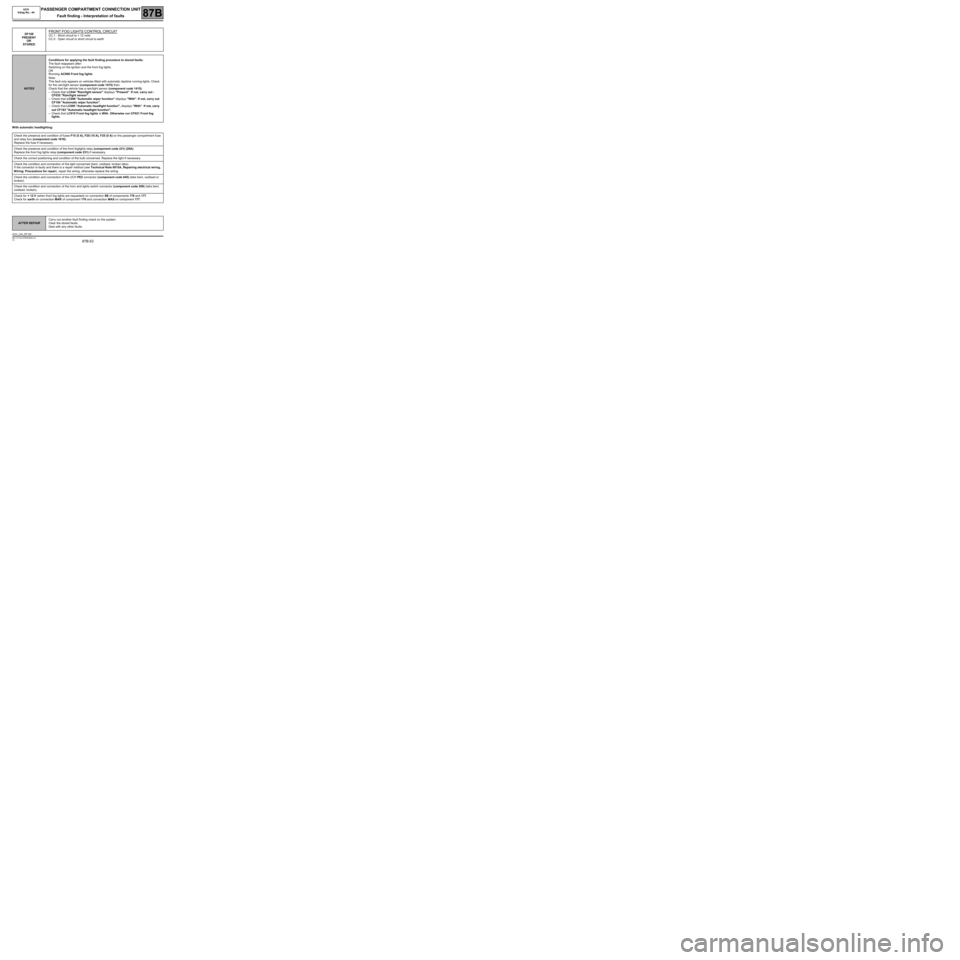
With automatic headlighting:DF108
PRESENT
OR
STORED
FRONT FOG LIGHTS CONTROL CIRCUIT
CC.1 : Short circuit to + 12 volts
CC.0 : Open circuit or short circuit to earth
NOTESConditions for applying the fault finding procedure to stored faults:
The fault reappears after:
Switching on the ignition and the front fog lights.
OR
Running AC008 Front fog lights
Note:
This fault only appears on vehicles fitted with automatic daytime running lights. Check
for the rain/light sensor (component code 1415) then:
Check that the vehicle has a rain/light sensor (component code 1415):
–Check that LC044 "Rain/light sensor" displays "Present". If not, carry out -
CF035 "Rain/light sensor".
–Check that LC096 "Automatic wiper function" displays "With". If not, carry out
CF194 "Automatic wiper function".
–Check that LC095 "Automatic headlight function", displays "With". If not, carry
out CF193 "Automatic headlight function".
–Check that LC015 Front fog lights is With. Otherwise run CF021 Front fog
lights.
Check the presence and condition of fuses F15 (5 A), F20 (15 A), F25 (5 A) on the passenger compartment fuse
and relay box (component code 1016).
Replace the fuse if necessary.
Check the presence and condition of the front foglights relay (component code 231) (20A).
Replace the front fog lights relay (component code 231) if necessary.
Check the correct positioning and condition of the bulb concerned. Replace the light if necessary.
Check the condition and connection of the light concerned (bent, oxidised, broken tabs).
If the connector is faulty and there is a repair method (see Technical Note 6015A, Repairing electrical wiring,
Wiring: Precautions for repair), repair the wiring, otherwise replace the wiring.
Check the condition and connection of the UCH PE2 connector (component code 645) (tabs bent, oxidised or
broken).
Check the condition and connection of the horn and lights switch connector (component code 209) (tabs bent,
oxidised, broken).
Check for + 12 V (when front fog lights are requested) on connection 8B of components 176 and 177.
Check for earth on connection MAR of component 176 and connection MAS on component 177.
AFTER REPAIRCarry out another fault finding check on the system.
Clear the stored faults.
Deal with any other faults.
UCH_V44_DF108
Page 54 of 179
87B-54
MR-413-X44-87B000$384.mif
V5
PASSENGER COMPARTMENT CONNECTION UNIT
Fault finding - Interpretation of faults
UCH
Vdiag No.: 44
87B
DF108
CONTINUED
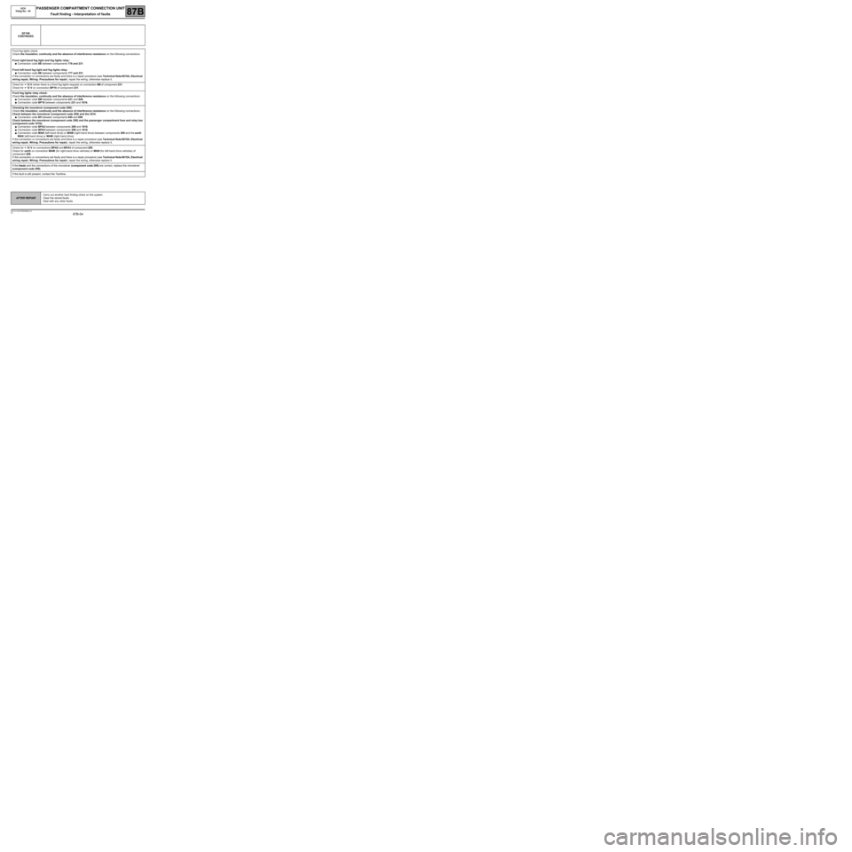
Front fog lights check:
Check the insulation, continuity and the absence of interference resistance on the following connections:
Front right-hand fog light and fog lights relay:
●Connection code 8B between components 176 and 231.
Front left-hand fog light and fog lights relay:
●Connection code 8B between components 177 and 231.
If the connection or connections are faulty and there is a repair procedure (see Technical Note 6015A, Electrical
wiring repair, Wiring: Precautions for repair), repair the wiring, otherwise replace it.
Check for + 12 V (when there is a front fog lights request) on connection 8M of component 231.
Check for + 12 V on connection BP16 of component 231.
Front fog lights relay check:
Check the insulation, continuity and the absence of interference resistance on the following connections:
●Connection code 8M between components 231 and 645.
●Connection code BP16 between components 231 and 1016.
Checking the monolever (component code 209):
Check the insulation, continuity and the absence of interference resistance on the following connections:
Check between the monolever (component code 209) and the UCH:
●Connection code 8H between components 645 and 209.
Check between the monolever (component code 209) and the passenger compartment fuse and relay box
(component code 1016):
●Connection code BPA2 between components 209 and 1016.
●Connection code BPA3 between components 209 and 1016.
●Connection code MAN (left-hand drive) or MAM (right-hand drive) between components 209 and the earth
MAN (left-hand drive) or MAM (right-hand drive).
If the connection or connections are faulty and there is a repair procedure (see Technical Note 6015A, Electrical
wiring repair, Wiring: Precautions for repair), repair the wiring, otherwise replace it.
Check for + 12 V on connections BPA2 and BPA3 of component 209.
Check for earth on connection MAM (for right-hand drive vehicles) or MAN (for left-hand drive vehicles) of
component 209.
If the connection or connections are faulty and there is a repair procedure (see Technical Note 6015A, Electrical
wiring repair, Wiring: Precautions for repair), repair the wiring, otherwise replace it.
If the feeds and the connections of the monolever (component code 209) are correct, replace the monolever
(component code 209).
If the fault is still present, contact the Techline.
AFTER REPAIRCarry out another fault finding check on the system.
Clear the stored faults.
Deal with any other faults.
Page 55 of 179
87B-55
MR-413-X44-87B000$432.mif
V5
87B
PASSENGER COMPARTMENT CONNECTION UNIT
Fault finding - Interpretation of faults
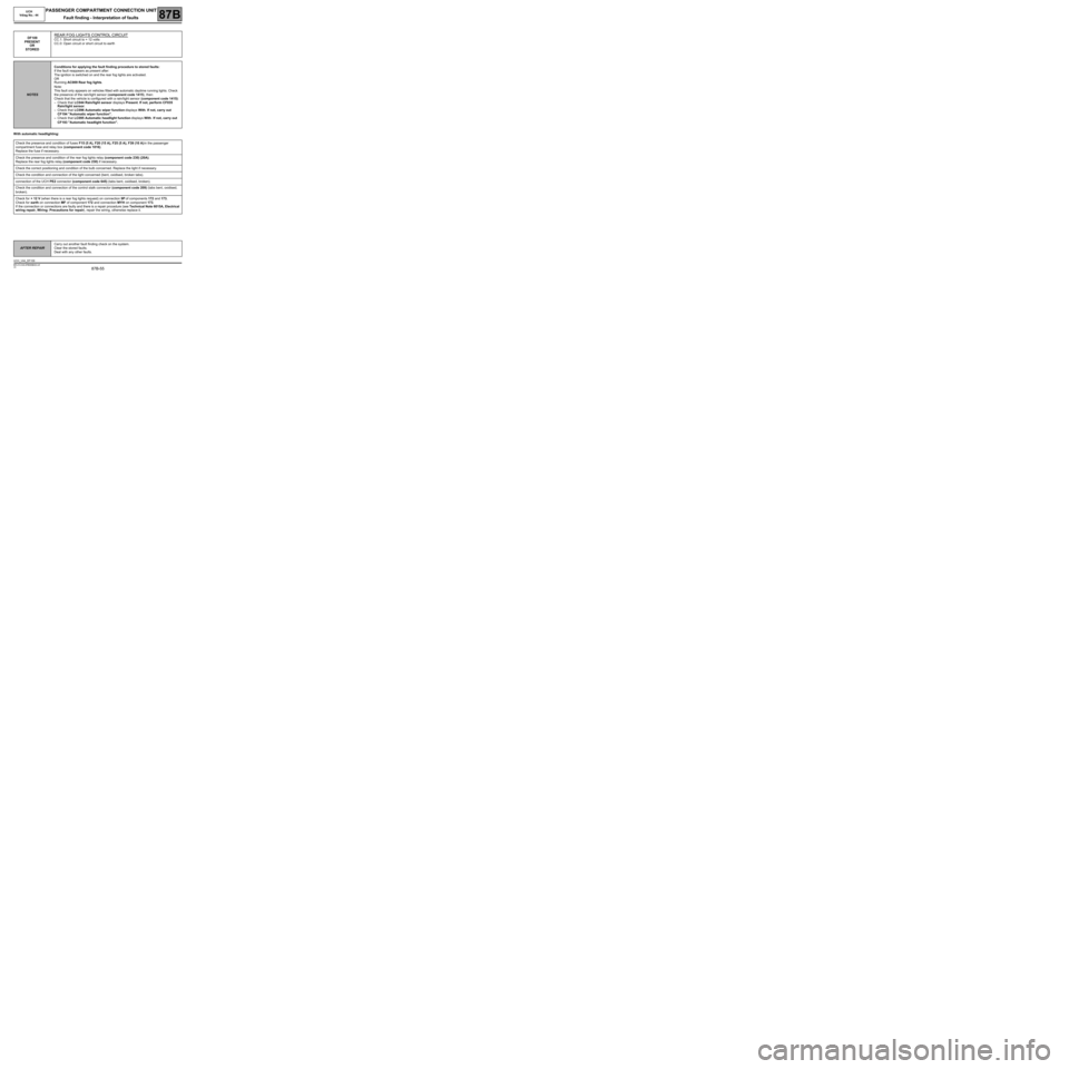
With automatic headlighting:DF109
PRESENT
OR
STORED
REAR FOG LIGHTS CONTROL CIRCUIT
CC.1: Short circuit to + 12 volts
CC.0: Open circuit or short circuit to earth
NOTESConditions for applying the fault finding procedure to stored faults:
If the fault reappears as present after:
The ignition is switched on and the rear fog lights are activated.
OR
Running AC009 Rear fog lights.
Note:
This fault only appears on vehicles fitted with automatic daytime running lights. Check
the presence of the rain/light sensor (component code 1415), then:
Check that the vehicle is configured with a rain/light sensor (component code 1415):
–Check that LC044 Rain/light sensor displays Present. If not, perform CF035
Rain/light sensor.
–Check that LC096 Automatic wiper function displays With. If not, carry out
CF194 "Automatic wiper function".
–Check that LC095 Automatic headlight function displays With. If not, carry out
CF193 "Automatic headlight function".
Check the presence and condition of fuses F15 (5 A), F20 (15 A), F25 (5 A), F39 (10 A) in the passenger
compartment fuse and relay box (component code 1016).
Replace the fuse if necessary.
Check the presence and condition of the rear fog lights relay (component code 230) (20A).
Replace the rear fog lights relay (component code 230) if necessary.
Check the correct positioning and condition of the bulb concerned. Replace the light if necessary.
Check the condition and connection of the light concerned (bent, oxidised, broken tabs).
connection of the UCH PE2 connector (component code 645) (tabs bent, oxidised, broken).
Check the condition and connection of the control stalk connector (component code 209) (tabs bent, oxidised,
broken).
Check for + 12 V (when there is a rear fog lights request) on connection 9P of components 172 and 173.
Check for earth on connection MF of component 172 and connection MYH on component 173.
If the connection or connections are faulty and there is a repair procedure (see Technical Note 6015A, Electrical
wiring repair, Wiring: Precautions for repair), repair the wiring, otherwise replace it.
AFTER REPAIRCarry out another fault finding check on the system.
Clear the stored faults.
Deal with any other faults.
UCH_V44_DF109
MR-413-X44-87B000$432.mif
UCH
Vdiag No.: 44
Page 56 of 179
87B-56
MR-413-X44-87B000$432.mif
V5
PASSENGER COMPARTMENT CONNECTION UNIT
Fault finding - Interpretation of faults
UCH
Vdiag No.: 44
87B
DF109
CONTINUED
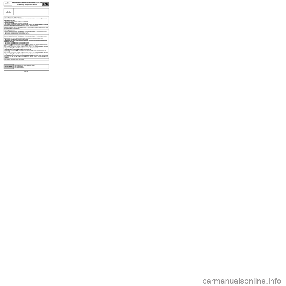
Rear fog lights and rear fog light relay check:
Check the insulation, continuity and the absence of interference resistance on the following connections:
Right-hand rear fog light:
●Connection code 9P between components 172 and 230.
Left-hand rear fog light:
●Connection code 9P between components 173 and 230.
If the connection or connections are faulty and there is a repair procedure (see Technical Note 6015A, Electrical
wiring repair, Wiring: Precautions for repair), repair the wiring, otherwise replace it.
Check for + 12 V (when there is a rear fog lights request) on connection 9W of component 230. Check for + 12 V
on connection BP16 of component 230.
Rear fog lights relay check:
Check the insulation, continuity and the absence of interference resistance of the following connections:
●Connection code 9W between components 230 and 645.
●Connection code BP16 between components 230 and 1016.
Control stalk check (component code 209):
Check the insulation, continuity and the absence of interference resistance of the following connections:
Check between the control stalk (component code 209) and the UCH (component code 645):
●Connection code 9B between components 645 and 209.
Check between the control stalk (component 209) and the passenger compartment fuse and relay box
(component code 1016):
●Connection code BPA2 between components 209 and 1016.
●Connection code BPA3 between components 209 and 1016.
Connection code MAM (for right-hand drive vehicles) or MAN (for left-hand drive vehicles) between component
209 and earth MAM (for right-hand drive vehicles) or MAN (for left-hand drive vehicles).
If the connection or connections are faulty and there is a repair procedure (see Technical Note 6015A, Electrical
wiring repair, Wiring: Precautions for repair), repair the wiring, otherwise replace it.
Check for + 12 V on connections BPA2 and BPA3 of component 209.
Check for earth on connection MAM (for right-hand drive vehicles) or MAN (for left-hand drive vehicles) of
component 209.
If the connection or connections are faulty and there is a repair procedure (see Technical Note 6015A, Electrical
wiring repair, Wiring: Precautions for repair), repair the wiring, otherwise replace it.
If the supplies and connections of the control stalk (component code 209) are correct, replace the control stalk
(component code 209). (See MR 411 Mechanical 84A, Control - Signals, Lighting - signals switch: Removal
- Refitting).
If the problem is still present, contact the Techline.
AFTER REPAIRCarry out another fault finding check on the system.
Clear the stored faults.
Deal with any other faults.
Page 57 of 179
87B-57
MR-413-X44-87B000$432.mif
V5
PASSENGER COMPARTMENT CONNECTION UNIT
Fault finding - Interpretation of faults
UCH
Vdiag No.: 44
87B
DF133
PRESENT
OR
STOREDDEADLOCKING MOTOR(S) CIRCUIT
CC.1: Short circuit to + 12 volts
CO.0: Open circuit or short circuit to earth
NOTESConditions for applying the fault finding procedure to stored faults:
If the fault reappears as present after:
The ignition is switched on and the deadlocking button has been pressed.
OR
Activation of AC035 Deadlocking.
Check that LC003 Deadlocking is definitely With. Otherwise, perform CF009
Deadlocking.
Check that LC040 Locking when driving is definitely With. Otherwise, perform
CF008 Locking when driving.
Ensure that the central door locking is correctly fixed; there must be no objects
preventing the central door locking from operating correctly.
Check that the doors and tailgate are closed correctly during the electrical
checks.
Check the presence and condition of fuse F14 (20 A) in the passenger compartment fuse and relay box
(component code 1016).
Replace the fuse if necessary.
Check the condition and connection of connectors PE1, PE2 and PE3 of the UCH (component code 645) (tabs
bent, oxidised, broken).
If the connection or connections are faulty and there is a repair procedure (see Technical Note 6015A, Electrical
wiring repair, Wiring: Precautions for repair), repair the wiring, otherwise replace it.
Check the condition and connection of the electric central door locking connectors for the driver's and passenger's
doors (tabs bent, oxidised, bent etc.).
If the connector is faulty and there is a repair method (see Technical Note 6015A, Repairing electrical wiring,
Wiring: Precautions for repair), repair the wiring, otherwise replace the wiring.
When deadlocking, check the signal status on components 140 and 141 of the following connections using an
oscilloscope (refer to test1 Central door locking).
Right or left-hand door locks:
Oscilloscope red test pin on connection 20AP of component 140 or 141.
Oscilloscope black test pin on connection 20C of component 140 or 141.
If the connection or connections are faulty and there is a repair procedure (see Technical Note 6015A, Electrical
wiring repair, Wiring: Precautions for repair), repair the wiring, otherwise replace it.
AFTER REPAIRCarry out another fault finding check on the system.
Clear the stored faults.
Deal with any other faults.
UCH_V44_DF133
Page 60 of 179
87B-60
MR-413-X44-87B000$432.mif
V5
PASSENGER COMPARTMENT CONNECTION UNIT
Fault finding - Interpretation of faults
UCH
Vdiag No.: 44
87B
DF134
PRESENT
OR
STOREDHAZARD WARNING LIGHTS INDICATOR LIGHT CIRCUIT
CC.0: Short circuit to earth or short circuit to + 12 V
NOTESConditions for applying the fault finding procedure to stored faults:
If the fault reappears as present after:
Switching on the ignition and pressing the hazard warning lights button.
OR
Activating AC52 Hazard warning lights indicator light.
Note: If the hazard warning lights do not light up during emergency braking, check
that LC018 Illumination of hazard warning lights by ABS is definitely With.
Otherwise, run CF024 Illumination of hazard warning lights by ABS.
Check the presence and condition of fuse F42 (10 A) in the passenger compartment fuse and relay box
(component code 1016).
Replace the fuse if necessary.
Check the condition and connection of the central door locking/warning switch connector (component code
1391) (tabs broken, bent, oxidised).
Check the condition and connection of connectors PE1 and PE2 of the UCH (component code 645) (tabs bent,
oxidised, broken).
Check for + 12 V on connection LPD of the locking/warning switch (component code 1391).
Check for earth on connection MAN of the locking/warning switch (component code 1391).
If the connector or connection is faulty and there is a repair procedure (see Technical Note 6015A, Electrical
wiring repair, Wiring: Precautions for repair), repair the wiring, otherwise replace it.
Switch check:
Check the insulation, continuity and the absence of interference resistance of the following connections:
●Connection code 64F between components 1391 and 645.
●Connection code 64Q between components 1391 and 645.
●Connection code MAN between component 1391 and earth MAN.
●Connection code LPD between components 1391 and 1016.
●Connection code 20AM between components 1391 and 645.
●Connection code 20AW between components 1391 and 645.
If the connection or connections are faulty and there is a repair procedure (see Technical Note 6015A, Electrical
wiring repair, Wiring: Precautions for repair), repair the wiring, otherwise replace it.
If the supply, earth and connections are correct, replace the door locking/warning switch (component code
1391) (see MR 411 Mechanical 84A, Control - Signals, Hazard warning lights and central door locking:
Removal - Refitting).
If the problem is still present, contact the Techline.
AFTER REPAIRCarry out another fault finding check on the system.
Clear the stored faults.
Deal with any other faults.
UCH_V44_DF134
Page 61 of 179
87B-61
MR-413-X44-87B000$432.mif
V5
PASSENGER COMPARTMENT CONNECTION UNIT
Fault finding - Interpretation of faults
UCH
Vdiag No.: 44
87B
DF135
DF136
PRESENT
OR
STOREDRAIN DETECTOR
LIGHT SENSOR
1.DEF: Internal electronic fault
NOTESConditions for applying the fault finding procedure to stored faults:
If the fault reappears as present after:
Switching on the ignition, activating automatic headlight lighting by moving the control
stalk twice in quick succession as follows: control stalk (component code 209) to
position zero ΑΕ control stalk (component code 209) to side lights position.
Status ET114 "Wiper request from rain sensor" should be "Low speed" or "High
speed" when the water runs over the position of the rain/light sensor on the
windscreen or status ET115 "Request for lights to be switched on from light
sensor" should be "Present" when an opaque cover is placed over the rain/light
sensor.
Note:
If there is an open circuit on connection BPT, there will be a malfunction on the
electric window winders, on the rain/light sensor, on the interior lights and the boot
lighting.
Check that the vehicle has a rain/light sensor (component code 1415).
Check that the vehicle is configured with a rain/light sensor (component code 1415).
Check that LC044 Rain/light sensor is Present. If not, perform CF035 Rain/light sensor.
Check that LC096 Automatic wiper function displays With. If not, carry out CF194 "Automatic wiper
function".
Check that LC095 Automatic headlight function displays With. If not, carry out CF193 "Automatic headlight
function".
Check the condition and position of supply fuses F2 (15 A), F8 (15 A), F19 (5 A), F27 (5 A) according to the
equipment, F29 (15 A) of the rain/light sensor (component code 1415) on the passenger compartment fuse and
relay box (component code 1016).
Replace the fuse if necessary.
Check the condition and connection of the 3-track connector of the rain/light sensor (component 1415) (tabs
bent, broken or oxidised).
Check the condition and connection of the PE2 connector of the UCH, (component code 645) (tabs bent,
oxidised, broken).
Check for + 12 V on connection BPT of component 1415.
Check for earth on connection MAM of component 1415.
AFTER REPAIRCarry out another fault finding check on the system.
Clear the stored faults.
Deal with any other faults.
UCH_V44_DF135 / UCH_V44_DF136
Page 67 of 179
87B-67
MR-413-X44-87B000$432.mif
V5
PASSENGER COMPARTMENT CONNECTION UNIT
Fault finding - Interpretation of faults
UCH
Vdiag No.: 44
87B
DF212
PRESENT
OR
STOREDALARM CIRCUIT
CC.0: Short circuit to earth
NOTESIf the vehicle is fitted with an alarm:
Check that the vehicle is configured with an alarm (component code 442).
Check that LC126 Alarm is definitely With. Otherwise, perform CF229 Alarm.
Check the condition and presence of fuses F6 (15 A) and F46 (15 A). Replace if necessary.
Check the condition and connection of the horn connector (component code 442) (tabs bent, oxidised, broken).
Check the continuity and insulation of the following connections:
●Connection code 20M between components 442 and 645.
●Connection code 64Q between components 442 and 645.
●Connection code AP3 between components 442 and 260.
●Connection code BCP4 between components 442 and 260.
●Connection code MG between component 442 and earth.
●Connection code 80A between components 442 and 438.
If the connection or connections are faulty and there is a repair procedure (see Technical Note 6015A, Electrical
wiring repair, Wiring: Precautions for repair), repair the wiring, otherwise replace it.
If the problem is still present, contact the Techline.
AFTER REPAIRCarry out another fault finding check on the system.
Clear the stored faults.
Deal with any other faults.
UCH_V44_DF212
Page 87 of 179
87B-87
MR-413-X44-87B000$576.mif
V5
PASSENGER COMPARTMENT CONNECTION UNIT
Fault finding - Interpretation of statuses
UCH
Vdiag No.: 44
87B
ET015
PASSENGER COMPARTMENT FAN
NOTESNo faults should be present or stored.
Apply this status for vehicles fitted with manual air conditioning or heating.
Apply the checks if there is an inconsistency between the value of the status
and the air actually blown.
SPECIFICATIONSRUNNING
STOPPED
Check the configuration of the heating and air conditioning type of the vehicle:
–Check that LC013 "Air conditioning type" is "Heating" or "Manual" or "Automatic" according to the
equipment level. Otherwise carry out CF019 Air conditioning type.
Check the presence and condition of fuses F28 (30 A), F29 (15 A), F42 (10 A) on the passenger compartment
fuse and relay box (component code 1016).
Replace the fuse(s) if necessary.
Check the condition and connection of the connectors for the air conditioning control panel and blower unit
(manual air conditioning) (tabs bent, oxidised, broken).
AFTER REPAIRRepeat the conformity check from the start.
Carry out fault finding on the system.
UCH_V44_ET015
Page 89 of 179
87B-89
MR-413-X44-87B000$576.mif
V5
PASSENGER COMPARTMENT CONNECTION UNIT
Fault finding - Interpretation of statuses
UCH
Vdiag No.: 44
87B
ET027
WINDSCREEN WIPER PARK POSITION
NOTESNo faults should be present or stored.
Note:
The park position (rest position) is used as a reference point by the UCH when the
ignition is switched of f whilst the wipers are operating and is required for intermittent
wiper operation.
SPECIFICATIONSACTIVE
INACTIVE
Check that fuse F2 (15 A) is sound and correctly fitted in the passenger compartment fuse and relay box.
Replace the fuse if necessary.
Check the condition and connection of the 5-track (OR) connector on the windscreen wiper motor (component
code 212) and UCH connector PE3 (tabs bent, broken, oxidised).
Check that the earth on the MAS connection of component 212 is perfect.
If the connection is faulty and there is a repair procedure (see Technical Note 6015A, Electrical wiring repair,
Wiring: Precautions for repair), repair the wiring, otherwise replace it.
Check for + 12 V on connections 14A (high speed request) 14B and 14C (low speed request) of component
212 and on connector PE3 of the UCH (component code 645).
Check the mountings of the windscreen wiper motor (component code 212). Check that there is no point of
resistance on the windscreen wiper mechanism.
AFTER REPAIRRepeat the conformity check from the start.
Carry out fault finding on the system.
UCH_V44_ET027