belt RENAULT TWINGO RS 2009 2.G Engine And Peripherals Workshop Manual
[x] Cancel search | Manufacturer: RENAULT, Model Year: 2009, Model line: TWINGO RS, Model: RENAULT TWINGO RS 2009 2.GPages: 652
Page 384 of 652
13B-23
DIESEL INJECTION
High pressure pump: Removal - Refitting
K9K
13B
REFITTING
I - REFITTING PREPARATION OPERATION
a
aparts always to be replaced: Injection pump
sprocket nut
aparts always to be replaced: Front sub-frame
bolt
II - REFITTING OPERATION FOR PART
CONCERNED
aCheck that there is an indexing pin on the high pres-
sure pump shaft.
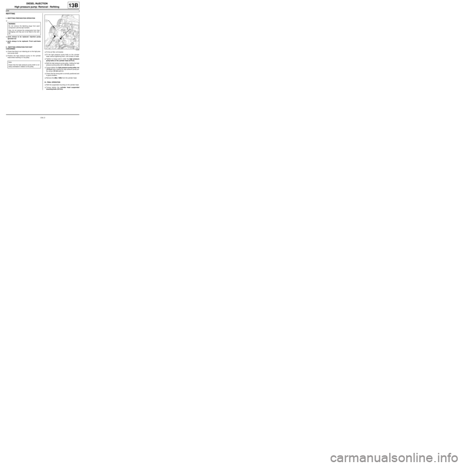
aPosition the high pressure pump on the cylinder
head whilst inserting it in its pulley.aFit the air filter unit bracket.
aFit the high pressure pump bolts on the cylinder
head, without tightening them, until contact is made.
aTighten to torque and in order the high pressure
pump bolts on the cylinder head (23 N.m).
aRefit the high pressure pump pulley, holding the high
pressure pump pulley with a 32 mm spanner.
aTorque tighten the high pressure pump pulley nut
(70 N.m) while holding the high pressure pump pul-
ley using a 32 mm spanner.
aCheck that the timing belt is correctly positioned and
in good condition.
aRemove the (Mot. 1606) from the cylinder head.
III - FINAL OPERATION
aRefit the suspended mounting on the cylinder head.
aTorque tighten the cylinder head suspended
mounting bolts (25 N.m). WARNING
Do not remove the blanking plugs from each
component until the last moment.
Also, do not remove the components from their
packaging until they are to be fitted to the vehi-
cle.
Note:
Check that the high pressure pump shaft is cor-
rectly orientated in relation to the pulley.
102085
Page 385 of 652
13B-24
DIESEL INJECTION
High pressure pump: Removal - Refitting
K9K
13B
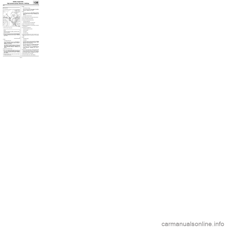
aRefit the lower timing cover.
aRefit the accessories belt (see 11A, Top and front
of engine, Accessories belt: Removal - Refitting,
page 11A-3)
aRefit:
-the upper timing cover,
-the camshaft position sensor (see 13B, Diesel in-
jection, Camshaft position sensor: Removal -
Refitting, page 13B-14) ,
-the right-hand suspended engine mounting (see
19D, Engine mounting, Right-hand suspended
engine mounting: Removal - Refitting, page
19D-13) .
aRemove the blanking plugs.
aRefit a high pressure pipe between the pump and
the rail (see 13B, Diesel injection, High pressure
pipe between pump and rail: Removal - Refitting,
page 13B-35) .
aConnect the diesel return pipe to the venturi fitted to
the high pressure pump.aRefit:
-the fuel filter mounting,
-the fuel filter (see 13A, Fuel supply, Fuel filter:
Removal - Refitting, page 13A-4) .
aRefit:
-the engine tie-bar (see 19D, Engine mounting,
Lower engine tie-bar: Removal - Refitting, page
19D-18) ,
-the engine harness channel.
aFit the engine wiring on the engine wiring channel.
aClip on the engine wiring channel.
aConnect to the high pressure pump:
-the diesel supply pipe,
-the diesel return pipe to the diesel filter.
aClip on the high pressure pump pipes.
aRemove the protection on the alternator to prevent
fuel flowing out.
aConnect the connectors of:
-the diesel temperature sensor,
-the flow actuator,
-the injectors,
-the heater plugs.
aRemove the blanking cover which protects the oil
level dipstick guide inlet opening on the cylinder
block.
aRefit:
-the dipstick guide,
-the dipstick,
-the scoop under the scuttle panel grille (see Scoop
under the scuttle panel grille: Removal - Refit-
ting) (56A, Exterior equipment),
-the scuttle panel grille (see Scuttle panel grille:
Removal - Refitting) (56A, Exterior equipment),
-the windscreen wiper arms (see Windscreen wip-
er arm: Removal - Refitting) (85A, Wiping -
Washing).
aPrime the fuel circuit with a manual priming pump
until the disconnected pipes are filled with fuel; if
necessary, bleed the fuel filter (see 13A, Fuel sup-
ply, Fuel filter: Removal - Refitting, page 13A-4) .
aCheck that there are no fuel leaks.
aConnect the battery (see ) (80A, Battery). K9K, and 740
19659
Note:
Make sure that the tab (23) is positioned oppo-
site the mark (24) .
Page 440 of 652
16A-1
STARTING - CHARGING
Alternator: Removal - Refitting
D4F or D7F, and STANDARD HEATING
16A
REMOVAL
I - REMOVAL PREPARATION OPERATION
aDisconnect the battery (see ) (MR 411, 80A, Bat-
tery).
aRemove:
-the front right-hand wheel (see Wheel: Removal -
Refitting) (MR 411, 35A, Wheels and tyres),
-the front right-hand wheel arch liner (see Front
wheel arch liner: Removal - Refitting) (MR 412,
55A, Exterior protection).
aUndo the lower bolt on the sub-frame tie-rod.
aRemove the upper bolt from the sub-frame tie-rod.
aRemove the sub-frame tie-rod.
aRemove the accessories belt (see 11A, Top and
front of engine, Accessories belt: Removal - Re-
fitting, page 11A-3) . Tightening torquesm
alter nator bolts25 Nm
sub-frame tie-rod lower
bolt62 Nm
sub-frame tie-rod upper
bolt21 Nm
Page 442 of 652
16A-3
STARTING - CHARGING
Alternator: Removal - Refitting
D4F or D7F, and STANDARD HEATING
16A
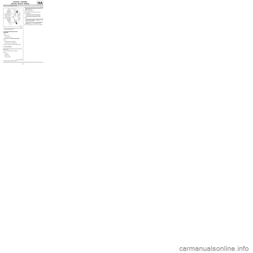
aPress in the rings (6) using pliers or a vice to make
the fitting operation easier.
II - REFITTING OPERATION FOR PART
CONCERNED
aRefit:
-the alternator,
-the alternator bolts.
aTorque tighten the alternator bolts (25 Nm).
aRefit:
-the power lead on the alternator,
-the power lead nut on the alternator.
aConnect the alternator excitation lead connector.
III - FINAL OPERATION
aConnect the fuel pipe to the injector rail.
aRefit:
-the dipstick,
-the filler neck,
-the filler neck bolt.
aAlways replace the accessories belt.aRefit the new accessories belt (see 11A, Top and
front of engine, Accessories belt: Removal - Re-
fitting, page 11A-3) .
aFit the sub-frame tie-rod.
aRefit the upper bolt on the sub-frame tie-rod.
aTorque tighten:
-the sub-frame tie-rod lower bolt (62 Nm),
-the sub-frame tie-rod upper bolt (21 Nm).
aRefit:
-the front right-hand wheel arch liner (see Front
wheel arch liner: Removal - Refitting) (MR 412,
55A, Exterior protection),
-the front right-hand wheel (see Wheel: Removal -
Refitting) (MR 411, 35A, Wheels and tyres).
aConnect the battery (see ) (MR 411, 80A, Battery).
18987
D4F, and 780
Page 443 of 652
16A-4
STARTING - CHARGING
Alternator: Removal - Refitting
D4F or D7F, and AIR CONDITIONING
16A
REMOVAL
I - REMOVAL PREPARATION OPERATION
aPosition the vehicle on a two-post lift (see Vehicle:
Towing and lifting) (02A, Lifting equipment).
aDisconnect the battery (see Battery: Removal - Re-
fitting) (80A, Battery).
aRemove:
-the front right-hand wheel (see Wheel: Removal -
Refitting) (35A, Wheels and tyres),
-the front right-hand wheel arch liner (see Front
wheel arch liner: Removal - Refitting) (55A, Ex-
terior protection),
-the accessories belt (see 11A, Top and front of
engine, Accessories belt: Removal - Refitting,
page 11A-3) .
aRemove the air filter unit (see 12A, Fuel mixture,
Air filter unit: Removal - Refitting, page 12A-13) .
aRemove the inlet distributor (see 12A, Fuel mixture,
Inlet distributor: Removal - Refitting, page 12A-
29) .II - OPERATION FOR REMOVAL OF PART
CONCERNED
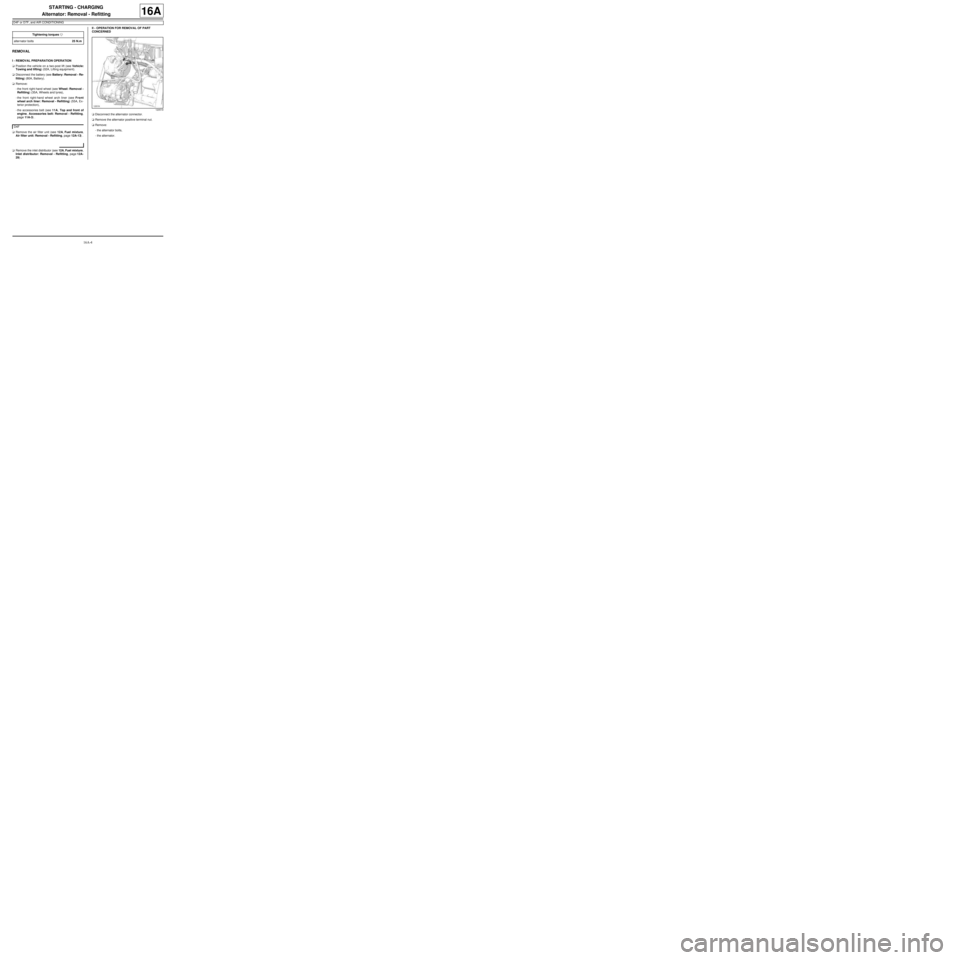
aDisconnect the alternator connector.
aRemove the alternator positive terminal nut.
aRemove:
-the alternator bolts,
-the alternator. Tightening torquesm
alter nator bolts25 N.m
D4F
120519
Page 444 of 652
16A-5
STARTING - CHARGING
Alternator: Removal - Refitting
D4F or D7F, and AIR CONDITIONING
16A
REFITTING
I - REFITTING PREPARATION OPERATION
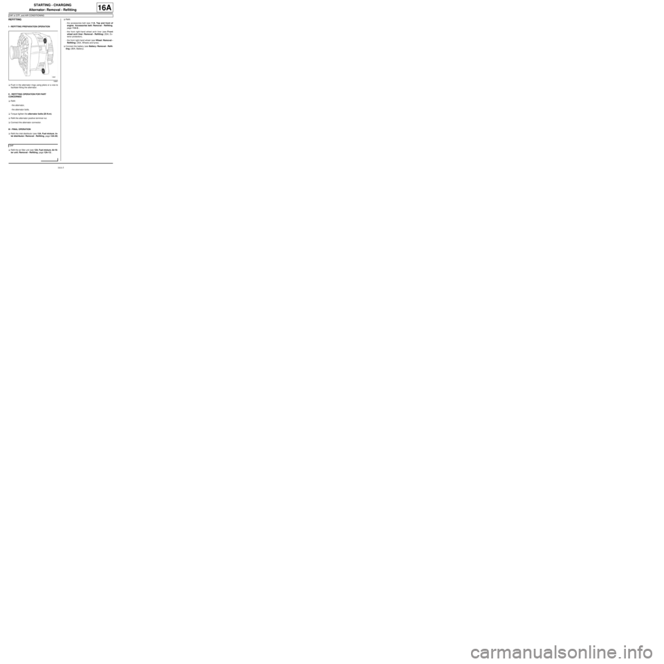
aPush in the alternator rings using pliers or a vice to
facilitate fitting the alternator.
II - REFITTING OPERATION FOR PART
CONCERNED
aRefit:
-the alternator,
-the alternator bolts.
aTorque tighten the alternator bolts (25 N.m).
aRefit the alternator positive terminal nut.
aConnect the alternator connector.
III - FINAL OPERATION
aRefit the inlet distributor (see 12A, Fuel mixture, In-
let distributor: Removal - Refitting, page 12A-29)
.
aRefit the air filter unit (see 12A, Fuel mixture, Air fil-
ter unit: Removal - Refitting, page 12A-13) .aRefit:
-the accessories belt (see 11A, Top and front of
engine, Accessories belt: Removal - Refitting,
page 11A-3) ,
-the front right-hand wheel arch liner (see Front
wheel arch liner: Removal - Refitting) (55A, Ex-
terior protection),
-the front right-hand wheel (see Wheel: Removal -
Refitting) (35A, Wheels and tyres).
aConnect the battery (see Battery: Removal - Refit-
ting) (80A, Battery).
18987
D4F
Page 445 of 652
16A-6
STARTING - CHARGING
Alternator: Removal - Refitting
K9K
16A
aFor removing and refitting the alternator (see 11A,
Top and front of engine, Accessories belt: Re-
moval - Refitting, page 11A-3) .
aFor removing and refitting the alternator (see 11A,
Top and front of engine, Accessories belt: Re-
moval - Refitting, page 11A-3) . AIR CONDITIONING or CLIMATE CONTROL
STANDARD HEATING
Page 446 of 652
16A-7
STARTING - CHARGING
Alternator: Removal - Refitting
K4M
16A
REMOVAL
I - REMOVAL PREPARATION OPERATION
aPosition the vehicle on a two-post lift (see Vehicle:
Towing and lifting) (02A, Lifting equipment).
aDisconnect the battery (see Battery: Removal - Re-
fitting) (80A, Battery).
aRemove:
-the engine undertray,
-the front right-hand wheel (see Wheel: Removal -
Refitting) (35A, Wheels and tyres),
-the front right-hand wheel arch liner (see Front
wheel arch liner: Removal - Refitting) (55A, Ex-
terior protection),
-the front bumper (see Front bumper: Removal -
Refitting) (55A, Exterior protection),
-the headlights (see Halogen headlight: Removal
- Refitting) (80B, Headlights),
-the bonnet catch (see Bonnet lock: Removal -
Refitting) (52A, Non-side opening element mecha-
nisms),
-the front upper cross member (see Front upper
cross member: Removal - Refitting) (42A, Upper
front structure),
-the accessories belt (see 11A, Top and front of
engine, Accessories belt: Removal - Refitting,
page 11A-3) .II - REMOVAL OPERATION
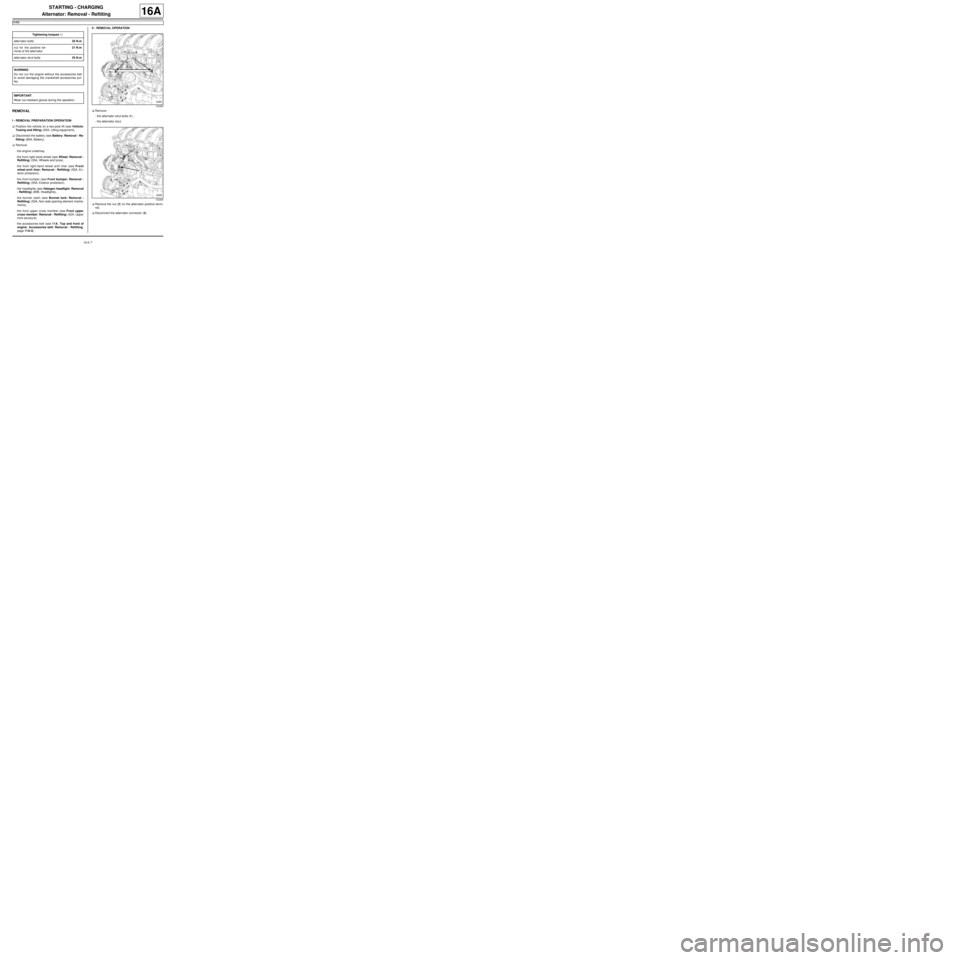
aRemove:
-the alternator strut bolts (1) ,
-the alternator strut.
aRemove the nut (2) on the alternator positive termi-
nal.
aDisconnect the alternator connector (3) . Tightening torquesm
alter nator bolts25 N.m
nut for the positive ter-
minal of the alternator21 N.m
alter nator strut bolts25 N.m
WARNING
Do not r un the engine without the accessories belt
to avoid damaging the crankshaft accessories pul-
ley.
IMPORTANT
Wear cut-resistant gloves during the operation.
132363
132365
Page 448 of 652
16A-9
STARTING - CHARGING
Alternator: Removal - Refitting
K4M
16A
aRefit the alternator strut.
aTighten to torque and in order the alternator strut
bolts (25 N.m).
III - FINAL OPERATION
aRefit:
-the accessories belt (see 11A, Top and front of
engine, Accessories belt: Removal - Refitting,
page 11A-3) ,
-the front upper cross member (see Front upper
cross member: Removal - Refitting) (42A, Upper
front structure),
-the bonnet catch (see Bonnet lock: Removal -
Refitting) (52A, Non-side opening element mecha-
nisms),
-the headlights (see Halogen headlight: Removal
- Refitting) (80B, Headlights),
-the front bumper (see Front bumper: Removal -
Refitting) (55A, Exterior protection),
-the front right-hand wheel arch liner (see Front
wheel arch liner: Removal - Refitting) (55A, Ex-
terior protection),
-the front right-hand wheel (see Wheel: Removal -
Refitting) (35A, Wheels and tyres),
-the engine undertray.
aConnect the battery (see Battery: Removal - Refit-
ting) (80A, Battery).
132363
Page 519 of 652
19A-9
COOLING
Cooling system: Draining - Refilling
D4F or D7F or K4M or K9K
19A
a
I - DRAINING
aPosition the vehicle on a two-post lift (see Vehicle:
Towing and lifting) (02A, Lifting equipment).
aRemove the expansion bottle cap.aRemove the engine undertray.
aPosition the coolant recovery tray under the vehi-
cle.
aRemove the cooling radiator bottom hose clip using
the tool (Mot. 1202-01) or (Mot. 1202-02) or (Mot.
1448).
aOpen the cooling system by removing the cooling ra-
diator bottom hose using the tool (Car. 1363).
aUse a compressed air nozzle to blow air into the
system through the expansion bottle opening to re-
move as much coolant as possible.
II - CLEANING
aFill the cooling system with water through the expan-
sion bottle.
aLet the water run until the water collected by the
cooling radiator bottom hose becomes clear.
aUse a compressed air nozzle to blow air into the
circuit through the expansion bottle opening to re-
move as much water as possible.
aRefit the hose which was removed.
III - FILLING
a
1 - Filling procedure with the tool (Mot. 1700)
aFill the cooling system with engine coolant recom-
mended by the manufacturer (see Vehicle: Parts
and consumables for the repair) (04B, Consum-
ables - Products) using the tool (Mot. 1700).
For the use of this tool (see Cooling system filling
and diagnostic tool: Use) (NT 3857A, 19A, Cool-
ing). Special tooling required
Mot. 1202-01Clip pliers for hose clips
(large size).
Mot. 1202-02Clip pliers for hose clips
(small size)
Mot. 1448Remote operation pliers for
hose clips .
Car. 1363Set of tr im removal levers.
Mot. 1700Fault finding and filling -
bleeding the cooling circuit.
Ms. 554-07Instr ument for testing the
cooling circuit and the expan-
sion bottle valve. Contains
caps 554-01, 554-04, 554-06
Equipment required
coolant recovery tray
compressed air nozzle
pedal press
IMPORTANT
When working in the engine compartment, take
care as the radiator fan(s) may start up unex-
pectedly (risk of being cut).
To avoid any risk of serious burns when the
engine is hot:
-do not open the expansion bottle cap,
-do not dr ain the cooling system,
-do not open the bleed screw(s).
WARNING
Before the operation, protect the electrical acces-
sories to prevent any risk of short circuiting and
protect the belts to avoid damaging them.
K4M
Note:
There are two procedures for filling the cooling
system:
-the method using the (Mot. 1700) tool is recom-
mended by Renault. It saves a considerable
amount of time because it does not require the
cooling system bleed screws to be opened,
-the procedure without a special tool.