battery RENAULT TWINGO RS 2009 2.G Engine And Peripherals Workshop Manual
[x] Cancel search | Manufacturer: RENAULT, Model Year: 2009, Model line: TWINGO RS, Model: RENAULT TWINGO RS 2009 2.GPages: 652
Page 571 of 652
19A-61
COOLING
Coolant pump inlet pipe: Removal - Refitting
D4F, and 780 or 782
19A
REMOVAL
I - REMOVAL PREPARATION OPERATION
aPosition the vehicle on a two-post lift (see Vehicle:
Towing and lifting) (02A, Lifting equipment).
aDisconnect the battery (see ) (80A, Battery).
aRemove the engine undertray.
aDrain the cooling system (see 19A, Cooling, Cool-
ing system: Draining - Refilling, page 19A-9) .
II - OPERATION FOR REMOVAL OF PART
CONCERNED
aSeparate the clips on the coolant pump inlet pipe
hoses using the tool (Mot. 1448).
aDisconnect the coolant pump inlet pipe hoses.
aRemove:
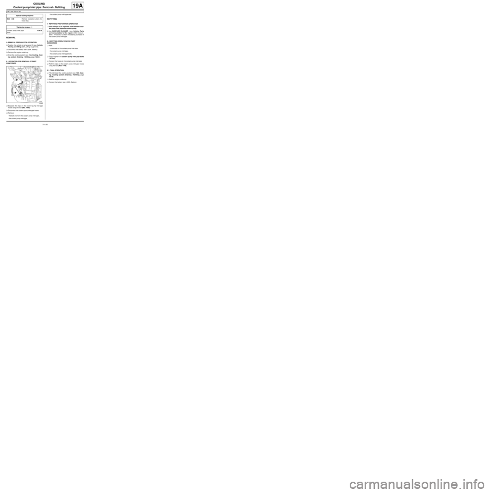
-the bolts (1) from the coolant pump inlet pipe,
-the coolant pump inlet pipe,-the coolant pump inlet pipe seal.
REFITTING
I - REFITTING PREPARATION OPERATION
aparts always to be replaced: seal between cool-
ant pump inlet pipe and coolant pump.
aUse SURFACE CLEANER (see Vehicle: Parts
and consumables for the repair) (04B, Consum-
ables - Products) to clean the bearing surfaces of
the coolant pump inlet pipe.
II - REFITTING OPERATION FOR PART
CONCERNED
aRefit:
-a new seal on the coolant pump inlet pipe,
-the coolant pump inlet pipe,
-the coolant pump inlet pipe bolts.
aTorque tighten the coolant pump inlet pipe bolts
(10 N.m).
aConnect the hoses to the coolant pump inlet pipe.
aRefit the clips on the coolant pump inlet pipe hoses
using the tool (Mot. 1448).
III - FINAL OPERATION
aFill and bleed the cooling system (see 19A, Cool-
ing, Cooling system: Draining - Refilling, page
19A-9) .
aRefit the engine undertray.
aConnect the battery (see ) (80A, Battery). Special tooling required
Mot. 1448Remote operation pliers for
hose clips .
Tightening torquesm
coolant pump inlet pipe
bolts10 N.m
120956
Page 572 of 652
19A-62
COOLING
Coolant pump inlet pipe: Removal - Refitting
K4M
19A
REMOVAL
I - REMOVAL PREPARATION OPERATION
aPosition the vehicle on a two-post lift (see Vehicle:
Towing and lifting) (02A, Lifting equipment).
aDisconnect the battery (see ) (80A, Battery).
aRemove the engine undertray.
aDrain the cooling system (see 19A, Cooling, Cool-
ing system: Draining - Refilling, page 19A-9) .
aRemove:
-the dipstick,
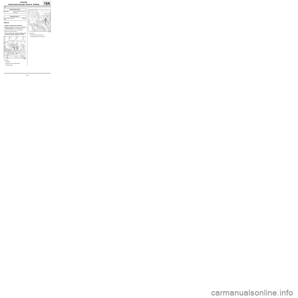
-the bolts (1) from the dipstick guide,
-the dipstick guide.aDisconnect:
-the pinking sensor connector (2) ,
-the oil pressure sensor connector (3) . Special tooling required
Mot. 1448Remote operation pliers for
hose clips .
Tightening torquesm
coolant pump inlet pipe
bolts25 N.m
132368
132374
Page 573 of 652
19A-63
COOLING
Coolant pump inlet pipe: Removal - Refitting
K4M
19A
II - REMOVAL OPERATION
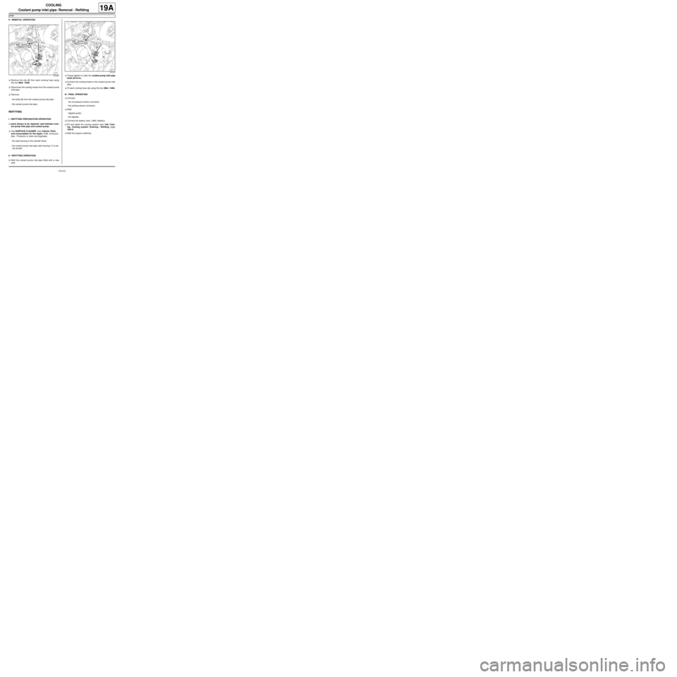
aRemove the clip (4) from each cooling hose using
the tool (Mot. 1448).
aDisconnect the cooling hoses from the coolant pump
inlet pipe.
aRemove:
-the bolts (5) from the coolant pump inlet pipe,
-the coolant pump inlet pipe.
REFITTING
I - REFITTING PREPARATION OPERATION
aparts always to be replaced: seal between cool-
ant pump inlet pipe and coolant pump.
aUse SURFACE CLEANER (see Vehicle: Parts
and consumables for the repair) (04B, Consuma-
bles - Products) to clean and degrease:
-the seal housing in the cylinder block,
-the coolant pump inlet pipe seal housing if it is be-
ing reused.
II - REFITTING OPERATION
aRefit the coolant pump inlet pipe fitted with a new
seal.aTorque tighten in order the coolant pump inlet pipe
bolts (25 N.m).
aConnect the cooling hoses to the coolant pump inlet
pipe.
aFit each cooling hose clip using the tool (Mot. 1448).
III - FINAL OPERATION
aConnect:
-the oil pressure sensor connector,
-the pinking sensor connector.
aRefit:
-dipstick guide ,
-the dipstick.
aConnect the battery (see ) (80A, Battery).
aFill and bleed the cooling system (see 19A, Cool-
ing, Cooling system: Draining - Refilling, page
19A-9) .
aRefit the engine undertray.
131781
131781
Page 594 of 652
19B-12
EXHAUST
Catalytic converter: Removal - Refitting
K9K
19B
PARTS AND CONSUMABLES FOR THE REPAIR
Pièces à remplacer systématiquement :
-air inlet pipe seals,
-the catalytic converter seal on the turbocharger,
-any stud and/or nut on the turbocharger or damaged
catalytic converter,
-The exhaust system sealing ring on the catalytic con-
verter.
Ingrédients :
-ABRASIVE PADS,
-SURFACE CLEANER.
REMOVAL
I - REMOVAL PREPARATION OPERATION
aPosition the vehicle on a two-post lift ( (see Vehicle:
Towing and lifting) ).
aDisconnect the battery ( (see Battery: Removal -
Refitting) ).
aRemove:
-the windscreen wiper arms ( (see Windscreen
wiper arm: Removal - Refitting) ),
-the scuttle panel grille ( (see Scuttle panel grille:
Removal - Refitting) ),
-the scoop under the scuttle panel grille ( (see
Scoop under the scuttle panel grille: Removal -
Refitting) ),
-the air filter box (see 12A, Fuel mixture, Air filter
unit: Removal - Refitting, page 12A-13) .
II - OPERATION FOR REMOVAL OF PART
CONCERNED
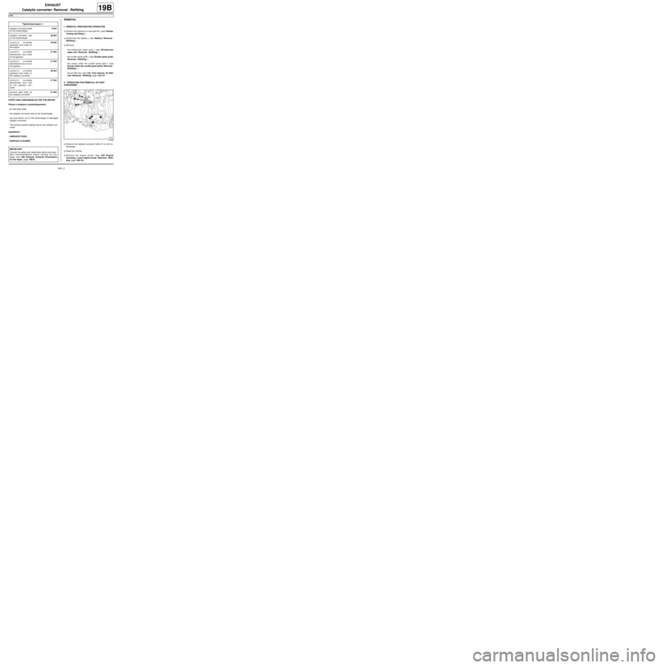
aRemove the catalytic converter bolts (1) on the tur-
bocharger.
aRaise the vehicle.
aRemove the engine tie-bar (see 19D, Engine
mounting, Lower engine tie-bar: Removal - Refit-
ting, page 19D-18) . Tightening torquesm
catalytic converter studs
on the turbocharger9 Nm
catalytic converter nuts
on the turbocharger26 Nm
catalytic converter
upstream strut bolts on
the engine44 Nm
catalytic converter
downstream strut bolts
on the gearbox21 Nm
catalytic converter
downstream strut nut on
the gearbox21 Nm
catalytic converter
upstream strut bolts on
the catalytic converter26 Nm
catalytic converter
downstream strut bolt
on the catalytic con-
verter21 Nm
exhaust pipe bolts on
the catalytic converter21 Nm
IMPORTANT
Consult the safety and cleanliness advice and oper-
ation recommendations before carrying out any
repair (see 19B, Exhaust, Exhaust: Precautions
for the repair, page 19B-8) .
112328
Page 596 of 652
19B-14
EXHAUST
Catalytic converter: Removal - Refitting
K9K
19B
aIf they are replaced, torque tighten the catalytic
converter studs on the turbocharger (9 Nm ).
II - REFITTING OPERATION FOR PART
CONCERNED
aFrom underneath the vehicle, fit:
-the catalytic converter on the turbocharger fitted
with a new seal between the catalytic converter
and the turbocharger,
-one of the catalytic converter nuts on the turbo-
charger.
aIn order, fit (without tightening):
-the catalytic converter upstream strut bolts on the
engine,
-the catalytic converter downstream strut bolt and
nut on the gearbox,
-the catalytic converter upstream strut bolts on the
catalytic converter,
-the catalytic converter downstream strut bolt on the
catalytic converter,
-the catalytic converter nuts on the turbocharger,
aTorque tighten and in order:
-the catalytic converter nuts on the turbocharger
(26 Nm),
-the catalytic converter upstream strut bolts on
the engine (44 Nm),
-the catalytic converter downstream strut bolts
on the gearbox (21 Nm),
-the catalytic converter downstream strut nut on
the gearbox (21 Nm),
-the catalytic converter upstream strut bolts on
the catalytic converter (26 Nm),
-the catalytic converter downstream strut bolt
on the catalytic converter (21 Nm).
aFit in order:
-a new exhaust system sealing ring on the catalytic
converter,
-the exhaust pipe on the catalytic converter,
-the exhaust pipe springs and bolts on the catalytic
converter.aTorque tighten the exhaust pipe bolts on the cata-
lytic converter (21 Nm).
aCheck the following and deal with if necessary:
-that there is no contact with the underbody,
-the presence and correct positioning of all the ex-
haust pipe heat shields.
III - FINAL OPERATION.
aRefit:
-the engine tie-bar (see 19D, Engine mounting,
Lower engine tie-bar: Removal - Refitting, page
19D-18) ,
-the air filter box (see 12A, Fuel mixture, Air filter
unit: Removal - Refitting, page 12A-13) ,
-the scoop under the scuttle panel grille ( (see
Scoop under the scuttle panel grille: Removal -
Refitting) ),
-the scuttle panel grille ( (see Scuttle panel grille:
Removal - Refitting) ),
-the windscreen wiper arms ( (see Windscreen
wiper arm: Removal - Refitting) ).
aConnect the battery ( (see Battery: Removal - Re-
fitting) ).
aStart the engine.
aCheck that there are no leaks and deal with them if
necessary. Note:
Check that there is no contact between the cata-
lytic conver ter and the turbocharger oil return
pipe during the entire catalytic converter tighten-
ing operation.
Page 598 of 652
19B-16
EXHAUST
Catalytic converter: Removal - Refitting
D4F, and 780 or 782
19B
REMOVAL
I - REMOVAL PREPARATION OPERATION
aPosition the vehicle on a two-post lift (see Vehicle:
Towing and lifting) (MR 411, 02A, Lifting equip-
ment).
aDisconnect the battery (see Battery: Removal - Re-
fitting) (MR 411, 80A, Battery).
aRemove:
-the air filter unit (see 12A, Fuel mixture, Air filter
unit: Removal - Refitting, page 12A-13) ,
-the air filter box strut bolt,-the air filter box strut,
-the upstream oxygen sensor (see 17B, Petrol in-
jection, Oxygen sensors: Removal - Refitting,
page 17B-13) . Tightening torquesm
catalytic converter lower
bracket bolt on the gear-
box44 N.m
bolts of the catalytic
converter lower bracket
on the engine25 N.m
side bracket bolts on the
catalytic converter21 N.m
side bracket bolts on the
engine21 N.m
catalytic converter nuts
on the turbocharger (ini-
tial torque)20 N.m
catalytic converter nuts
on the turbocharger30 N.m
bolts of the catalytic
converter lower bracket
on the catalytic con-
verter (initial torque)20 N.m
bolts of the catalytic
converter lower bracket
on the catalytic con-
verter30 N.m
exhaust downpipe bolts21 N.m
catalytic converter strut
nut21 N.m
catalytic converter strut
bolt on the rocker cover21 N.m
Page 603 of 652
19B-21
EXHAUST
Catalytic converter: Removal - Refitting
D4F, and 780 or 782
19B
aConnect the battery (see Battery: Removal - Refit-
ting) (MR 411, 80A, Battery).
Page 615 of 652
19C-1
TANK
Fuel tank: Draining
K9K
19C
I - DRAINING PREPARATION OPERATION
aDisconnect the battery (see ) (MR 441, 80A, Bat-
tery).
aRemove the front engine cover.aDisconnect the engine fuel supply quick-release
union (1) from the fuel filter outlet.
II - DRAINING THE FUEL TANK
aConnect a pneumatic transfer pump for fuels to
the fuel filter outlet.
aDrain the fuel tank.
III - FINAL OPERATION.
aDisconnect the pneumatic transfer pump for fuels
from the fuel filter.
aConnect the engine fuel filter outlet engine supply
quick-release union to the fuel filter.
aRefit the engine cover.
aConnect the battery (see ) (MR 441, 80A, Battery). Equipment required
pneumatic transfer pump for fuels
IMPORTANT
During this oper ation, be sure to:
-refrain from smoking or bringing red hot objects
close to the working area,
-be careful of fuel splashes when disconnecting the
union.
IMPORTANT
Wear goggles with side protectors for this opera-
tion.
IMPORTANT
Wear latex gloves during the operation.
WARNING
To prevent impurities from entering the circuit, plugs
must be fitted to the openings of all the fuel circuit
components exposed to the open air.
WARNING
To avoid any corrosion or damage, protect the
areas on which fuel is likely to run.
121441
Page 616 of 652
19C-2
TANK
Fuel tank: Draining
D4F or D7F or K4M
19C
I - DRAINING PREPARATION OPERATION
aDisconnect the battery (see ) (80A, Battery).
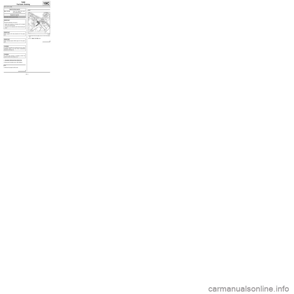
aRemove the engine oil filler neck.aDisconnect the fuel supply union (1) from the injector
rail.
aFit a T (Mot. 1311-08) union. Special tooling required
Mot. 1311-08Union for taking fuel pres-
sure measurements .
Equipment required
pneumatic transfer pump for fuels
IMPORTANT
During this oper ation, be sure to:
-refrain from smoking or bringing red hot objects
close to the working area,
-be careful of fuel splashes when disconnecting the
union.
IMPORTANT
Wear goggles with side protectors for this opera-
tion.
IMPORTANT
Wear leaktight gloves (Nitrile type) for this opera-
tion.
WARNING
To prevent impurities from entering the circuit, place
protective plugs on all fuel circuit components
exposed to the open air.
WARNING
To avoid any corrosion or damage, protect the
areas on which fuel is likely to run.
D4F
D4F
121778
Page 617 of 652
19C-3
TANK
Fuel tank: Draining
D4F or D7F or K4M
19C
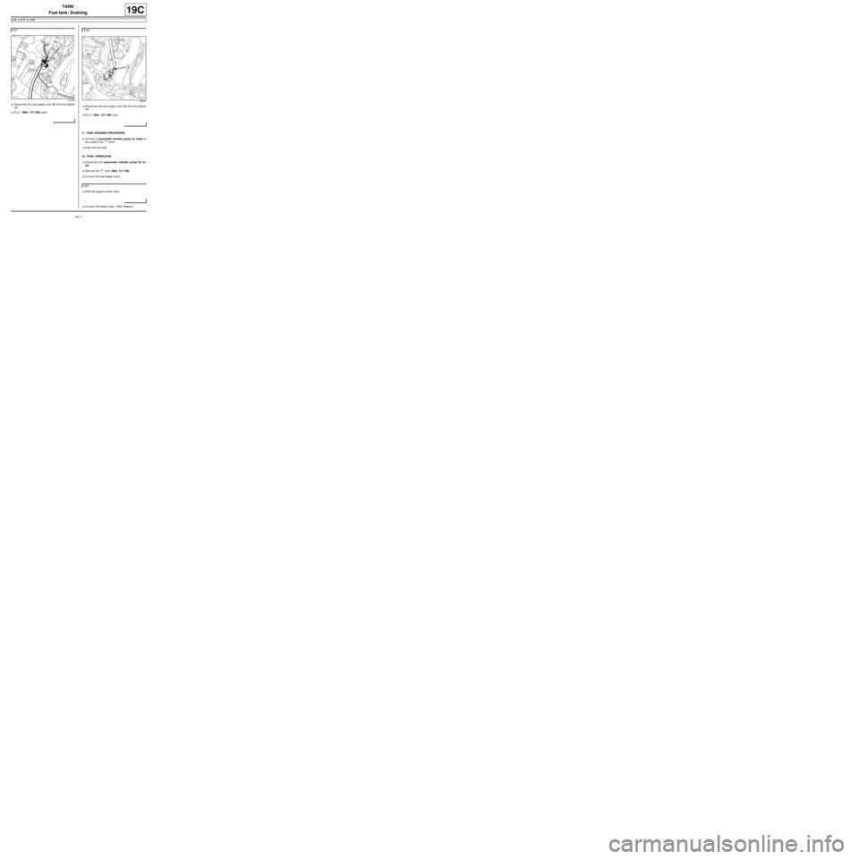
aDisconnect the fuel supply union (2) from the injector
rail.
aFit a T (Mot. 1311-08) union.aDisconnect the fuel supply union (3) from the injector
rail.
aFit a T (Mot. 1311-08) union.
II - TANK DRAINING PROCEDURE
aConnect a pneumatic transfer pump for fuels on
the outlet of the "T" union.
aDrain the fuel tank.
III - FINAL OPERATION.
aDisconnect the pneumatic transfer pump for fu-
els. .
aRemove the “T” union (Mot. 1311-08).
aConnect the fuel supply union.
aRefit the engine oil filler neck.
aConnect the battery (see ) (80A, Battery). D7F
121779
K4M
132334
D4F