Fuel supply RENAULT TWINGO RS 2009 2.G Engine And Peripherals User Guide
[x] Cancel search | Manufacturer: RENAULT, Model Year: 2009, Model line: TWINGO RS, Model: RENAULT TWINGO RS 2009 2.GPages: 652
Page 183 of 652
11A-66
TOP AND FRONT OF ENGINE
Rocker cover: Removal - Refitting
D7F
11A
REMOVAL
I - REMOVAL PREPARATION OPERATION
aDisconnect the battery ( (see Battery: Removal -
Refitting) ).
aRemove:
-the intake distributor (see 12A, Fuel mixture, Inlet
distributor: Removal - Refitting, page 12A-29) ,
-the air filter box (see 12A, Fuel mixture, Air filter
unit: Removal - Refitting, page 12A-13) .
aUnclip:
-The harness from the heat shield,
-the brake servo pipe from the heat shield.
aDisconnect the ignition coil supply.
II - OPERATION FOR REMOVAL OF PART
CONCERNED
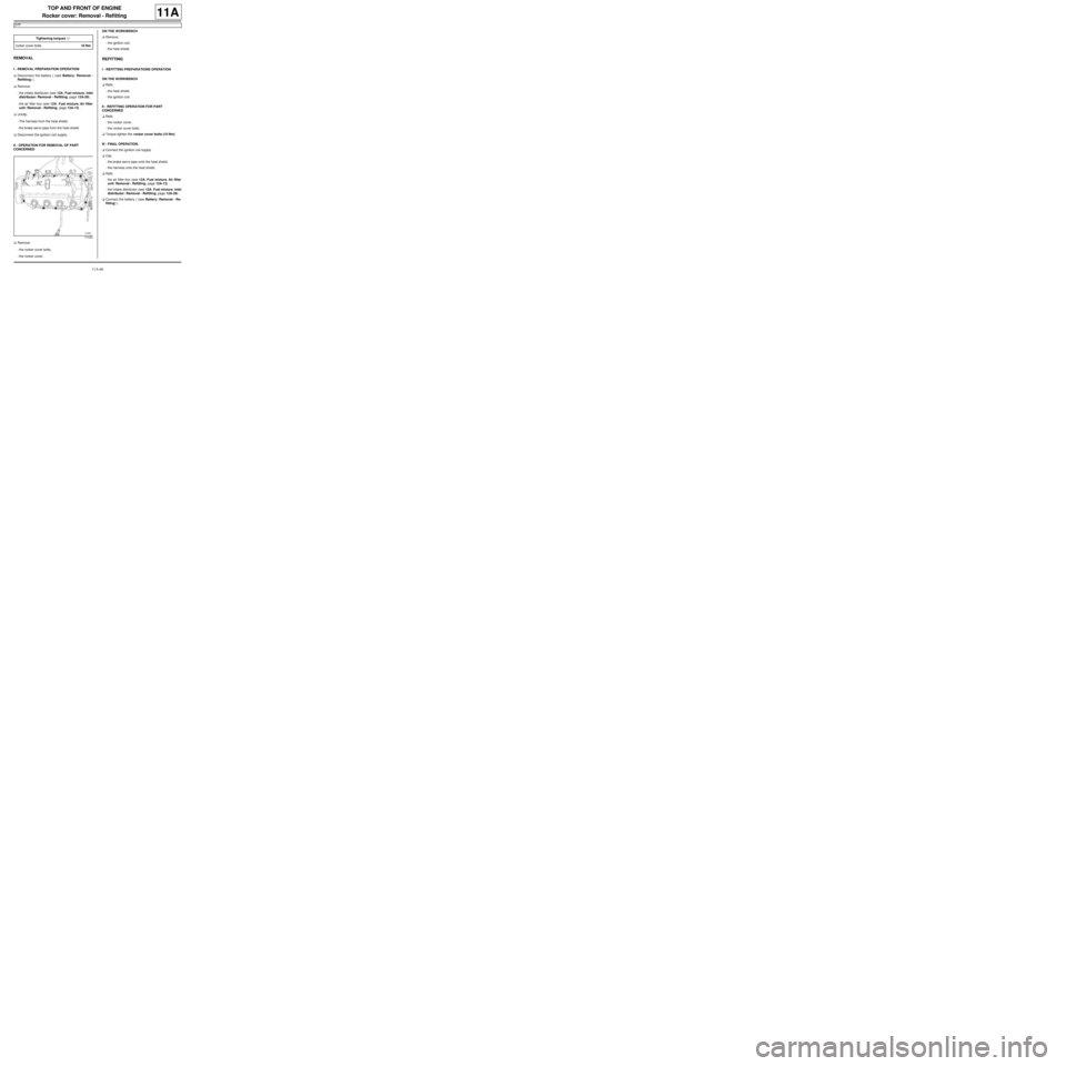
aRemove:
-the rocker cover bolts,
-the rocker cover.ON THE WORKBENCH
aRemove:
-the ignition coil,
-the heat shield.
REFITTING
I - REFITTING PREPARATIONS OPERATION
ON THE WORKBENCH
aRefit:
-the heat shield,
-the ignition coil.
II - REFITTING OPERATION FOR PART
CONCERNED
aRefit:
-the rocker cover,
-the rocker cover bolts.
aTorque tighten the rocker cover bolts (10 Nm).
III - FINAL OPERATION.
aConnect the ignition coil supply.
aClip:
-the brake servo pipe onto the heat shield,
-the harness onto the heat shield.
aRefit:
-the air filter box (see 12A, Fuel mixture, Air filter
unit: Removal - Refitting, page 12A-13) ,
-the intake distributor (see 12A, Fuel mixture, Inlet
distributor: Removal - Refitting, page 12A-29) .
aConnect the battery ( (see Battery: Removal - Re-
fitting) ). Tightening torquesm
rocker cover bolts10 Nm
110422
Page 186 of 652
11A-69
TOP AND FRONT OF ENGINE
Rocker cover: Removal - Refitting
D4F, and 772
11A
REMOVAL
I - REMOVAL PREPARATION OPERATION
aDisconnect the battery (see Battery: Removal - Re-
fitting) (80A, Battery).
aRemove:
-the air filter unit (see 12A, Fuel mixture, Air filter
unit: Removal - Refitting, page 12A-13) ,
-the inlet distributor (see 12A, Fuel mixture, Inlet
distributor: Removal - Refitting, page 12A-29) ,
-the ignition coil (see 17A, Ignition, Coils: Remov-
al - Refitting, page 17A-1) .
aUnclip the rocker cover electric wiring harnesses.
II - OPERATION FOR REMOVAL OF PART
CONCERNED
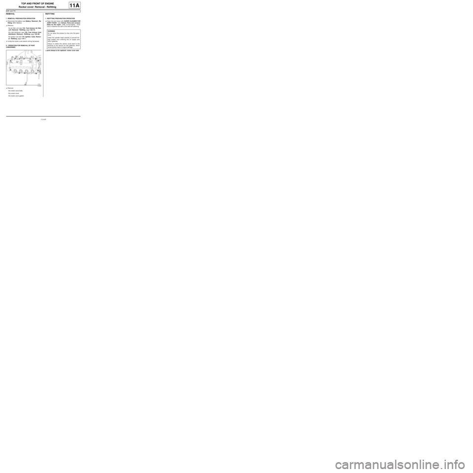
aRemove:
-the rocker cover bolts,
-the rocker cover,
-the rocker cover gasket.
REFITTING
I - REFITTING PREPARATION OPERATION
aClean the joint faces with SUPER CLEANER FOR
JOINT FACES (see Vehicle: Parts and consum-
ables for the repair) (04B, Consumables - Prod-
ucts) to dissolve any part of the seal still adhering.
aparts always to be replaced: rocker cover seal.
110422
WARNING
Do not allow this product to dr ip onto the paint-
work.
Clean the cylinder head carefully to prevent for-
eign bodies from entering the oil supply and
return galleries.
Failure to follow this advice could lead to the
blocking of the various oil inlet galleries, which
would quickly result in engine damage.
Page 190 of 652
11A-73
TOP AND FRONT OF ENGINE
Rocker cover: Removal - Refitting
D4F, and 780 or 782 or 784
11A
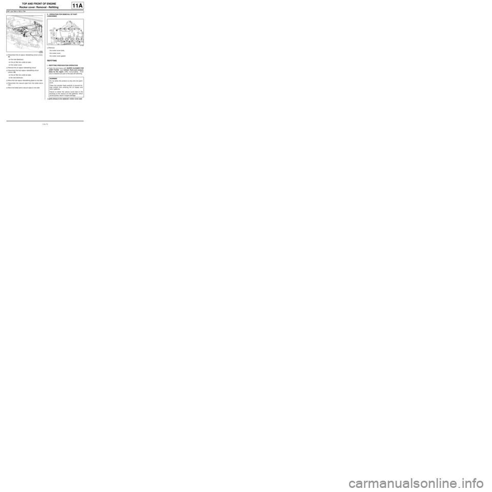
aDisconnect the oil vapour rebreathing circuit unions
(9) .
-on the inlet distributor,
-on the air filter box outlet air pipe,
-on the rocker cover.
aRemove the oil vapour rebreathing circuit.
aDisconnect the fuel vapour rebreathing circuit
unions (10) .
-on the air filter box outlet air pipe,
-to the inlet distributor.
aMove the fuel vapour rebreathing pipes to one side.
aDisconnect the vacuum pipe from the brake servo
(11) .
aMove the brake servo vacuum pipe to one side.II - OPERATION FOR REMOVAL OF PART
CONCERNED
aRemove:
-the rocker cover bolts,
-the rocker cover,
-the rocker cover gasket.
REFITTING
I - REFITTING PREPARATION OPERATION
aClean the joint faces with SUPER CLEANER FOR
JOINT FACES (see Vehicle: Parts and consum-
ables for the repair) (04B, Consumables - Prod-
ucts) to dissolve any part of the seal still adhering.
aparts always to be replaced: rocker cover seal.
122828
121026
WARNING
Do not allow this product to dr ip onto the paint-
work.
Clean the cylinder head carefully to prevent for-
eign bodies from entering the oil supply and
return galleries.
Failure to follow this advice could lead to the
blocking of the various oil inlet galleries, which
would quickly result in engine damage.
Page 248 of 652
11A-131
TOP AND FRONT OF ENGINE
Cylinder head: Removal - Refitting
D4F, and 780 or 782
11A
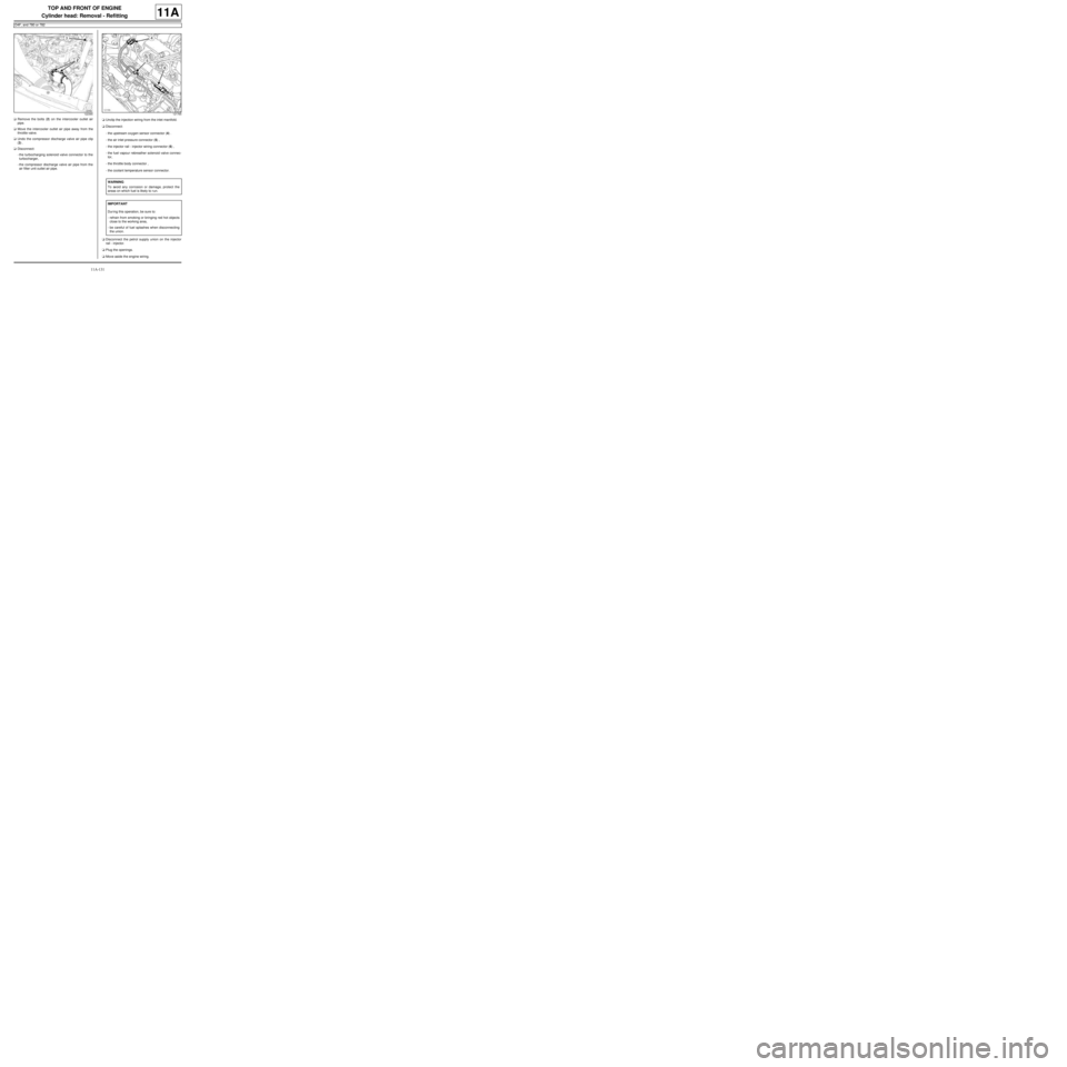
aRemove the bolts (2) on the intercooler outlet air
pipe.
aMove the intercooler outlet air pipe away from the
throttle valve.
aUndo the compressor discharge valve air pipe clip
(3) .
aDisconnect:
-the turbocharging solenoid valve connector to the
turbocharger,
-the compressor discharge valve air pipe from the
air filter unit outlet air pipe.aUnclip the injection wiring from the inlet manifold.
aDisconnect:
-the upstream oxygen sensor connector (4) .
-the air inlet pressure connector (5) ,
-the injector rail - injector wiring connector (6) ,
-the fuel vapour rebreather solenoid valve connec-
tor,
-the throttle body connector ,
-the coolant temperature sensor connector.
aDisconnect the petrol supply union on the injector
rail - injector.
aPlug the openings.
aMove aside the engine wiring.
122390121765
WARNING
To avoid any corrosion or damage, protect the
areas on which fuel is likely to r un.
IMPORTANT
Dur ing this operation, be sure to:
-refrain from smoking or bringing red hot objects
close to the working area,
-be careful of fuel splashes when disconnecting
the union.
Page 295 of 652
12A-30
FUEL MIXTURE
Inlet distributor: Removal - Refitting
D7F
12A
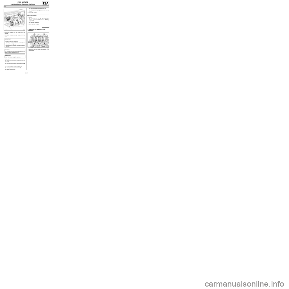
aDisconnect the spark plug high voltage wiring har-
ness (2) .
aMove aside the spark plug high voltage wiring har-
ness.
aDisconnect:
-the petrol vapour rebreather pipe from the inlet dis-
tributor (3) ,
-the non-return valve pipe on the inlet distributor (4)
,
-the air inlet pressure sensor connector (5) ,
-the air temperature sensor connector (6) ,
-the injector connector (7) ,-the fuel supply pipe intermediate union (8) ,
-the oil vapour rebreathing pipe from the inlet dis-
tributor.
aRemove the dipstick.
aRemove:
-the accessories belt (see 11A, Top and front of
engine, Accessories belt: Removal - Refitting,
page 11A-3) ,
-the alternator upper bolt.
aTilt the alternator forward.
II - OPERATION FOR REMOVAL OF PART
CONCERNED
aRemove the nuts from the air inlet distributor on the
cylinder head.
121737
IMPORTANT
During this operation, be sure to:
-refrain from smoking or bringing red hot objects
close to the working area,
-be careful of fuel splashes when disconnecting
the union.
WARNING
To avoid any corrosion or damage, protect the
areas on which fuel is likely to run.
IMPORTANT
Wear latex gloves during the operation.
AIR CONDITIONING
121734
Page 296 of 652
12A-31
FUEL MIXTURE
Inlet distributor: Removal - Refitting
D7F
12A
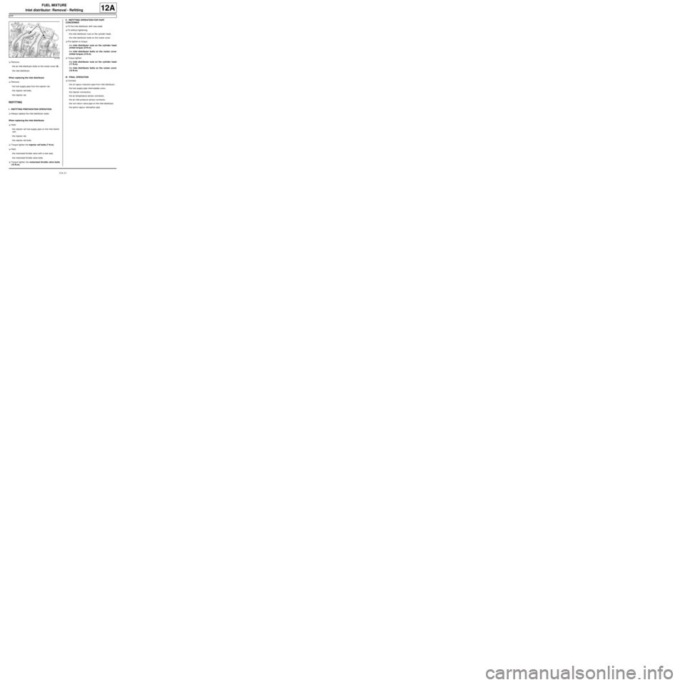
aRemove:
-the air inlet distributor bolts on the rocker cover (9) ,
-the inlet distributor.
When replacing the inlet distributor
aRemove:
-the fuel supply pipe from the injector rail,
-the injector rail bolts,
-the injector rail.
REFITTING
I - REFITTING PREPARATION OPERATION
aAlways replace the inlet distributor seals.
When replacing the inlet distributor
aRefit:
-the injector rail fuel supply pipe on the inlet distrib-
utor,
-the injector rail,
-the injector rail bolts.
aTorque tighten the injector rail bolts (7 N.m).
aRefit:
-the motorised throttle valve with a new seal,
-the motorised throttle valve bolts.
aTorque tighten the motorised throttle valve bolts
(10 N.m).II - REFITTING OPERATION FOR PART
CONCERNED
aFit the inlet distributor with new seals
aFit without tightening:
-the inlet distributor nuts on the cylinder head,
-the inlet distributor bolts on the rocker cover.
aPre-tighten to torque:
-the inlet distributor nuts on the cylinder head
(initial torque) (8 N.m),
-the inlet distributor bolts on the rocker cover
(initial torque) (3 N.m).
aTorque tighten:
-the inlet distributor nuts on the cylinder head
(17 N.m),
-the inlet distributor bolts on the rocker cover
(10 N.m).
III - FINAL OPERATION
aConnect:
-the oil vapour induction pipe from inlet distributor ,
-the fuel supply pipe intermediate union,
-the injector connectors,
-the air temperature sensor connector,
-the air inlet pressure sensor connector,
-the non-return valve pipe on the inlet distributor,
-the petrol vapour rebreather pipe.
121735
Page 298 of 652
12A-33
FUEL MIXTURE
Inlet distributor: Removal - Refitting
D4F, and 772
12A
REMOVAL
I - REMOVAL PREPARATION OPERATION
aRemove the air filter unit (see 12A, Fuel mixture,
Air filter unit: Removal - Refitting, page 12A-13) .
aUnclip the fuel supply pipe on the engine oil filler
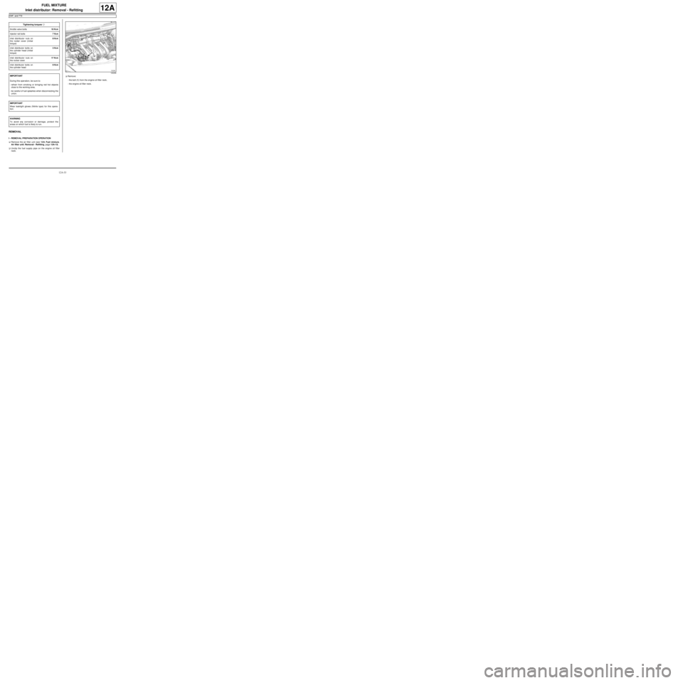
neck.aRemove:
-the bolt (1) from the engine oil filler neck,
-the engine oil filler neck. Tightening torquesm
throttle valve bolts10 N.m
injector rail bolts7 N.m
inlet distributor nuts on
the rocker cover (initial
torque)8 N.m
inlet distributor bolts on
the cylinder head (initial
torque)3 N.m
inlet distributor nuts on
the rocker cover17 N.m
inlet distributor bolts on
the cylinder head9 N.m
IMPORTANT
During this oper ation, be sure to:
-refrain from smoking or bringing red hot objects
close to the working area,
-be careful of fuel splashes when disconnecting the
union.
IMPORTANT
Wear leaktight gloves (Nitrile type) for this opera-
tion.
WARNING
To avoid any corrosion or damage, protect the
areas on which fuel is likely to run.
120299
Page 299 of 652
12A-34
FUEL MIXTURE
Inlet distributor: Removal - Refitting
D4F, and 772
12A
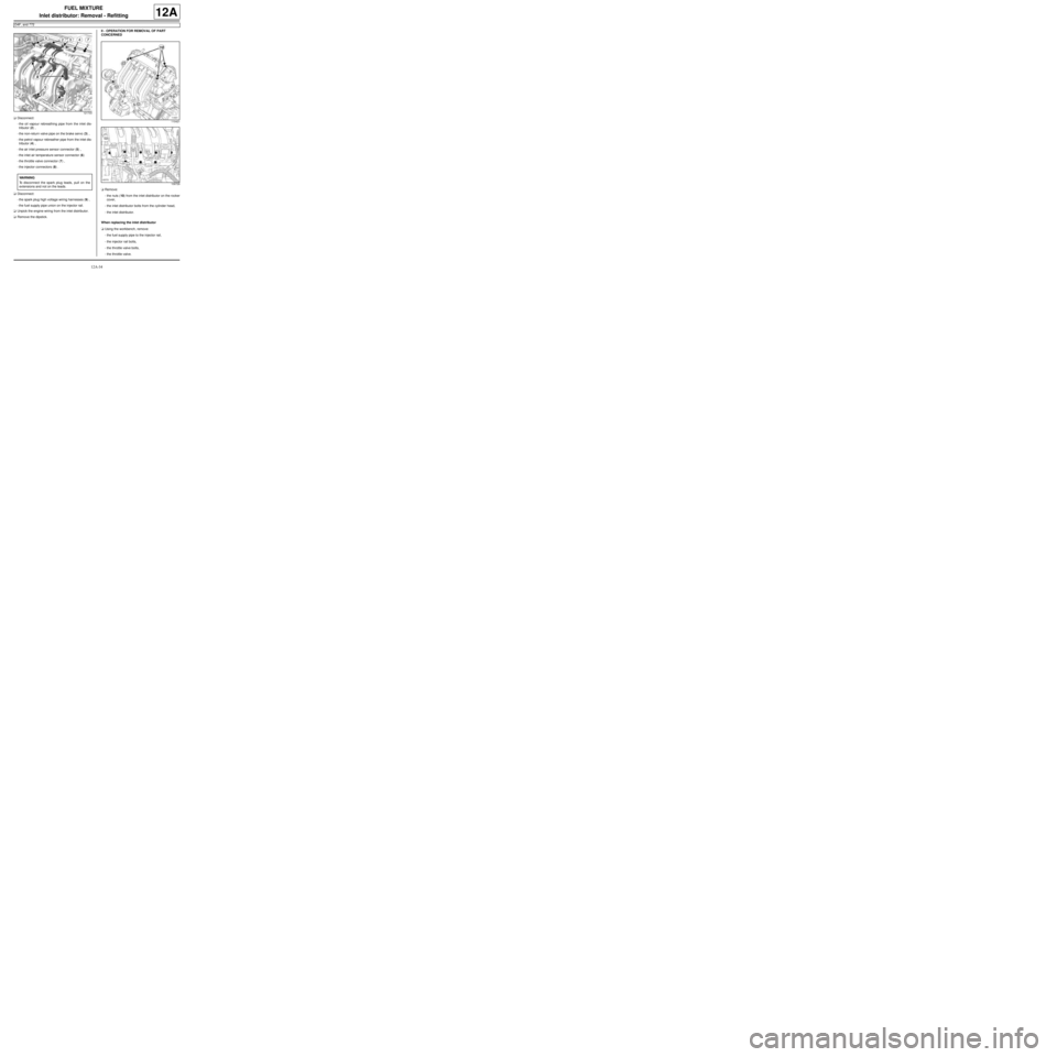
aDisconnect:
-the oil vapour rebreathing pipe from the inlet dis-
tributor (2) ,
-the non-return valve pipe on the brake servo (3) ,
-the petrol vapour rebreather pipe from the inlet dis-
tributor (4) ,
-the air inlet pressure sensor connector (5) ,
-the inlet air temperature sensor connector (6)
-the throttle valve connector (7) ,
-the injector connectors (8) .
aDisconnect:
-the spark plug high voltage wiring harnesses (9) ,
-the fuel supply pipe union on the injector rail.
aUnpick the engine wiring from the inlet distributor.
aRemove the dipstick.II - OPERATION FOR REMOVAL OF PART
CONCERNED
aRemove:
-the nuts (10) from the inlet distributor on the rocker
cover,
-the inlet distributor bolts from the cylinder head,
-the inlet distributor.
When replacing the inlet distributor
aUsing the workbench, remove:
-the fuel supply pipe to the injector rail,
-the injector rail bolts,
-the throttle valve bolts,
-the throttle valve.
121733
WARNING
To disconnect the spark plug leads, pull on the
extensions and not on the leads.
110421
109729
Page 301 of 652
12A-36
FUEL MIXTURE
Inlet distributor: Removal - Refitting
D4F, and 772
12A
III - FINAL OPERATION
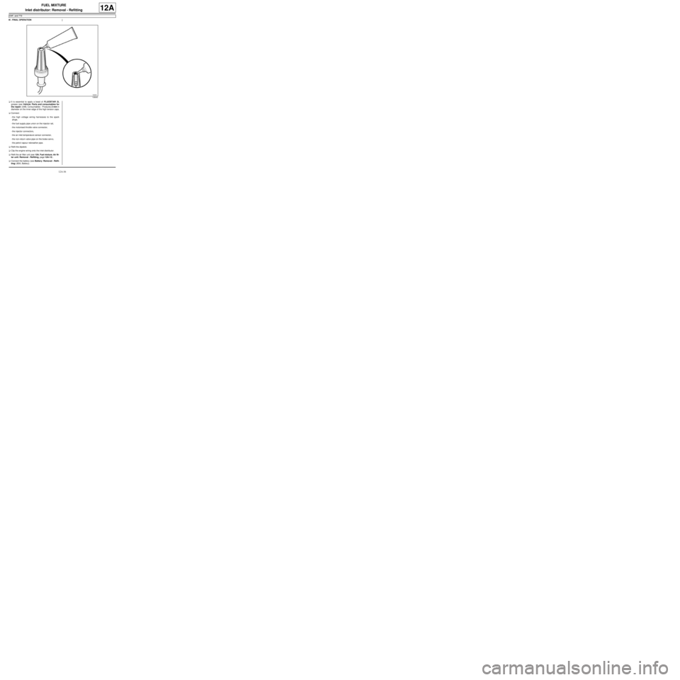
aIt is essential to apply a bead of FLUOSTAR 2L
grease (see Vehicle: Parts and consumables for
the repair) (04B, Consumables - Products) 2 mm in
diameter on the inner edge of the high tension caps.
aConnect:
-the high voltage wiring harnesses to the spark
plugs,
-the fuel supply pipe union on the injector rail,
-the motorised throttle valve connector,
-the injector connectors,
-the air inlet temperature sensor connector,
-the non-return valve pipe on the brake servo,
-the petrol vapour rebreather pipe.
aRefit the dipstick.
aClip the engine wiring onto the inlet distributor.
aRefit the air filter unit (see 12A, Fuel mixture, Air fil-
ter unit: Removal - Refitting, page 12A-13) .
aConnect the battery (see Battery: Removal - Refit-
ting) (80A, Battery).
106640
Page 333 of 652
12B-8
TURBOCHARGING
Turbocharger: Removal - Refitting
D4F, and 780 or 782
12B
REMOVAL
I - REMOVAL PREPARATION OPERATION
aPosition the vehicle on a two-post lift (see Vehicle:
Towing and lifting) (02A, Lifting equipment).
aDisconnect the battery (see Battery: Removal - Re-
fitting) (80A, Battery).
aRemove the engine undertray.
aDrain the manual gearbox (see Manual gearbox
oils: Draining - Filling) (21A, Manual gearbox).
aRemove:
-the air filter unit (see 12A, Fuel mixture, Air filter
unit: Removal - Refitting, page 12A-13) ,
-the upstream oxygen sensor (see 17B, Petrol in-
jection, Oxygen sensors: Removal - Refitting,
page 17B-13) ,
-the lower engine tie-bar (see 19D, Engine mount-
ing, Lower engine tie-bar: Removal - Refitting,
page 19D-18) ,
-the front right-hand wheel driveshaft (see Front
right-hand driveshaft: Removal - Refitting)
(29A, Driveshafts),
-the catalytic converter (see 19B, Exhaust, Cata-
lytic converter: Removal - Refitting, page 19B-
12) .II - OPERATION FOR REMOVAL OF PART
CONCERNED
aRemove the turbocharger oil return pipe (see 12B,
Turbocharging, Turbocharger oil pipe: Removal
- Refitting, page 12B-12) .
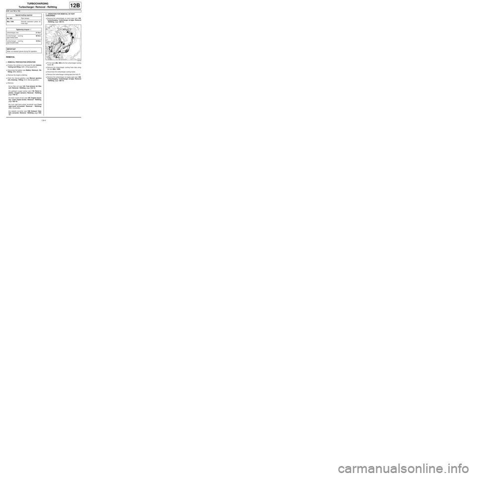
aFit the tools (Ms. 583) onto the turbocharger cooling
hoses (6) .
aRemove the turbocharger cooling hose clips using
the tool (Mot. 1448).
aDisconnect the turbocharger cooling hoses.
aRemove the turbocharger cooling pipe strut bolt (7) .
aRemove the turbocharger oil supply pipe (see 12B,
Turbocharging, Turbocharger oil pipe: Removal
- Refitting, page 12B-12) . Special tooling required
Ms. 583Pipe clamps .
Mot. 1448Remote operation pliers for
hose clips .
Tightening torquesm
turbocharger nuts21 N.m
turbocharger cooling
pipe hollow bolts30 N.m
turbocharger cooling
pipe bracket bolts10 N.m
IMPORTANT
Wear cut-resistant gloves during the operation.121773