Undertray bolts RENAULT TWINGO RS 2009 2.G Engine And Peripherals User Guide
[x] Cancel search | Manufacturer: RENAULT, Model Year: 2009, Model line: TWINGO RS, Model: RENAULT TWINGO RS 2009 2.GPages: 652
Page 79 of 652
10A-73
ENGINE AND CYLINDER BLOCK ASSEMBLY
Multifunction support: Removal - Refitting
K4M
10A
REFITTING
I - REFITTING OPERATION
aRefit the multifunction support.
aPretighten to torque multifunction support bolts 1
and 2 (initial torque) (5 N.m).
aLoosen bolts (1) and (2) on the multifunction support
by one half-turn.
aPre-tighten to torque:
-multifunction support bolt 7 on the cylinder
block (initial torque) (5 N.m),-multifunction support bolts 1 and 2 (initial
torque) (5 N.m),
-multifunction support bolts 6, 5, 4 and 3 (5
N.m).
aTighten to torque and in order:
-the multifunction support bolts (44 N.m),
-the multifunction support bolt on the cylinder
block (25 N.m) (7) .
II - FINAL OPERATION
aRefit:
-the air conditioning compressor (see Compressor:
Removal - Refitting) (62A, Air conditioning),
-the alternator (see 16A, Starting - Charging, Al-
ternator: Removal - Refitting, page 16A-1) ,
-the accessories belt (see 11A, Top and front of
engine, Accessories belt: Removal - Refitting,
page 11A-3) ,
-the front upper cross member (see Front upper
cross member: Removal - Refitting) (42A, Upper
front structure),
-the bonnet catch (see Bonnet lock: Removal -
Refitting) (52A, Non-side opening element mecha-
nisms),
-the headlights (see Halogen headlight: Removal
- Refitting) (80B, Headlights),
-the front bumper (see Front bumper: Removal -
Refitting) (55A, Exterior protection),
-the front right-hand wheel arch liner (see Front
wheel arch liner: Removal - Refitting) (55A, Ex-
terior protection),
-the front right-hand wheel (see Wheel: Removal -
Refitting) (35A, Wheels and tyres).
aFill the refrigerant circuit using a refrigerant charg-
ing station (see Refrigerant circuit: Draining -
Filling) (62A, Air conditioning).
aConnect the battery (see Battery: Removal - Refit-
ting) (80A, Battery).
aRefit the engine undertray.
131780
131779
Page 102 of 652
10A-96
ENGINE AND CYLINDER BLOCK ASSEMBLY
Engine - gearbox assembly: Removal - Refitting
K4M
10A
REMOVAL
I - REMOVAL PREPARATION OPERATION
aPosition the vehicle on a two-post lift (see Vehicle:
Towing and lifting) (02A, Lifting equipment).
aRemove the air filter unit (see 12A, Fuel mixture,
Air filter unit: Removal - Refitting, page 12A-13) .
aRemove the battery (see Battery: Removal - Refit-
ting) (80A, Battery).
aRemove:
-the petrol injection computer (see 17B, Petrol in-
jection, Petrol injection computer: Removal -
Refitting, page 17B-20) ,
-the battery tray (see Battery tray: Removal - Re-
fitting) (80A, Battery),
-the front wheels (see Wheel: Removal - Refitting)
(35A, Wheels and tyres),
-the engine undertray,
-the front wheel arch liners (see Front wheel arch
liner: Removal - Refitting) (55A, Exterior protec-
tion),
-the front bumper (see Front bumper: Removal -
Refitting) (55A, Exterior protection).
aDrain:
-the gearbox (see Manual gearbox oils: Draining -
Filling) (21A, Manual gearbox),-the cooling system (see 19A, Cooling, Cooling
system: Draining - Refilling, page 19A-9) ,
-the engine, if necessary (see 10A, Engine and
cylinder block assembly, Engine oil: Draining -
Refilling, page 10A-22) ,
-the refrigerant circuit using a refrigerant charging
station (see Refrigerant circuit: Draining - Fill-
ing) (62A, Air conditioning).
aAttach the « engine cooling radiator - condenser »
assembly to the front upper cross member.
aRemove:
-the engine tie-bar (see 19D, Engine mounting,
Lower engine tie-bar: Removal - Refitting, page
19D-18) ,
-the front axle subframe (see Front axle subframe:
Removal - Refitting) (31A, Front axle compo-
nents),
-the radiator mounting cross member (see Radiator
mounting cross member: Removal - Refitting)
(41A, Front lower structure),
-the front left-hand wheel driveshaft (see Front left-
hand driveshaft: Removal - Refitting) (29A,
Driveshafts),
-the front right-hand wheel driveshaft (see Front
right-hand driveshaft: Removal - Refitting)
(29A, Driveshafts),
-the differential output seal (see Differential output
seal: Removal - Refitting) (21A, Manual gear-
box).
aRemove the catalytic converter (see 19B, Exhaust,
Catalytic converter: Removal - Refitting, page
19B-12) . Special tooling required
Mot. 1448Remote operation pliers for
hose clips .
Equipment required
refrigerant charging station
Tightening torquesm
rubber pad mounting
bolts for the suspended
engine mounting on the
gearbox21 N.m
bolts of the suspended
mounting r ubber pad62 N.m
suspended engine
mounting shaft nut62 N.m
Page 116 of 652
10A-110
ENGINE AND CYLINDER BLOCK ASSEMBLY
Flywheel: Removal - Refitting
K4M
10A
REMOVAL
I - REMOVAL PREPARATION OPERATION
aPosition the vehicle on a two-post lift (see Vehicle:
Towing and lifting) (02A, Lifting equipment).
aRemove:
-the engine undertray,
-the battery (see Battery: Removal - Refitting)
(80A, Battery),
-the air filter unit (see 12A, Fuel mixture, Air filter
unit: Removal - Refitting, page 12A-13) ,
-the petrol injection computer (see 17B, Petrol in-
jection, Petrol injection computer: Removal -
Refitting, page 17B-20) ,
-the battery tray (see Battery tray: Removal - Re-
fitting) (80A, Battery),
-the front wheels (see Wheel: Removal - Refitting)
(35A, Wheels and tyres),
-the front wheel arch liners (see Front wheel arch
liner: Removal - Refitting) (55A, Exterior protec-
tion),
-the front bumper (see Front bumper: Removal -
Refitting) (55A, Exterior protection).
aDrain:
-the gearbox (see Manual gearbox oils: Draining -
Filling) (21A, Manual gearbox),
-the engine cooling system (see 19A, Cooling,
Cooling system: Draining - Refilling, page 19A-
9) ,
-the refrigerant circuit using a refrigerant charging
station (see Refrigerant circuit: Draining - Fill-
ing) (62A, Air conditioning).aRemove:
-the lower engine tie-bar (see 19D, Engine mount-
ing, Lower engine tie-bar: Removal - Refitting,
page 19D-18) ,
-the front axle subframe (see Front axle subframe:
Removal - Refitting) (31A, Front axle compo-
nents),
-the front left-hand wheel driveshaft (see Front left-
hand driveshaft: Removal - Refitting) (29A,
Driveshafts),
-the front right-hand wheel driveshaft (see Front
right-hand driveshaft: Removal - Refitting)
(29A, Driveshafts),
-the differential output seals (see Differential out-
put seal: Removal - Refitting) (21A, Manual gear-
box),
-the « engine - gearbox » assembly (see 10A, En-
gine and cylinder block assembly, Engine -
gearbox assembly: Removal - Refitting, page
10A-74) (21A, Manual gearbox),
-the manual gearbox (see Manual gearbox: Re-
moval - Refitting) ,
-the « pressure plate - disc » assembly (see Pres-
sure plate - Disc: Removal - Refitting) (20A,
Clutch).
II - REMOVAL OPERATION
aRemove:
-the flywheel bolts,
-the (Mot. 1677) (1) , Special tooling required
Mot. 1677Flywheel locking tool.
Equipment required
refrigerant charging station
Tightening torquesm
flywheel bolts70 N.m
109158
Page 117 of 652
10A-111
ENGINE AND CYLINDER BLOCK ASSEMBLY
Flywheel: Removal - Refitting
K4M
10A
-the flywheel.
REFITTING
I - REFITTING PREPARATION OPERATION
aUse SURFACE CLEANER (see Vehicle: Parts
and consumables for the repair) (04B, Consuma-
bles - Products) to clean and degrease:
-the flywheel bearing face if reusing,
-the crankshaft bearing face.
aAlways replace the flywheel bolts.
II - REFITTING OPERATION
aFit the flywheel.
aFit the new flywheel bolts without tightening them.
aPosition the (Mot. 1677).
aTighten to torque and in order the flywheel bolts
(70 N.m).
III - FINAL OPERATION
aRefit:
-the « pressure plate - disc » assembly (see Pres-
sure plate - Disc: Removal - Refitting) (20A,
Clutch),
-the manual gearbox (see Manual gearbox: Re-
moval - Refitting) (21A, Manual gearbox).-the « engine and gearbox » assembly (see 10A,
Engine and cylinder block assembly, Engine -
gearbox assembly: Removal - Refitting, page
10A-74) ,
-the differential output seals (see Differential out-
put seal: Removal - Refitting) (21A, Manual gear-
box),
-the front right-hand wheel driveshaft (see Front
right-hand driveshaft: Removal - Refitting)
(29A, Driveshafts),
-the front left-hand wheel driveshaft (see Front left-
hand driveshaft: Removal - Refitting) (29A,
Driveshafts),
-the front axle subframe (see Front axle subframe:
Removal - Refitting) (31A, Front axle compo-
nents),
-the lower engine tie-bar (see 19D, Engine mount-
ing, Lower engine tie-bar: Removal - Refitting,
page 19D-18) ,
-the front bumper (see Front bumper: Removal -
Refitting) (55A, Exterior protection),
-the front wheel arch liners (see Front wheel arch
liner: Removal - Refitting) (55A, Exterior protec-
tion),
-the front wheels (see Wheel: Removal - Refitting)
(35A, Wheels and tyres),
-the battery tray (see Battery tray: Removal - Re-
fitting) (80A, Battery),
-the petrol injection computer (see 17B, Petrol in-
jection, Petrol injection computer: Removal -
Refitting, page 17B-20) ,
-the air filter unit (see 12A, Fuel mixture, Air filter
unit: Removal - Refitting, page 12A-13) ,
-the battery (see Battery: Removal - Refitting)
(80A, Battery).
aPerform the following operations:
-fill and bleed the cooling system (see 19A, Cool-
ing, Cooling system: Draining - Refilling, page
19A-9) ,
-fill the gearbox (see Manual gearbox oils: Drain-
ing - Filling) (21A, Manual gearbox).
-fill the refrigerant circuit using a refrigerant charg-
ing station (see Refrigerant circuit: Draining -
Filling) (62A, Air conditioning).
aRefit the engine undertray.
109158
Page 134 of 652
11A-17
TOP AND FRONT OF ENGINE
Accessories belt: Removal - Refitting
K4M
11A
REMOVAL
I - REMOVAL PREPARATION OPERATION
aPosition the vehicle on a two-post lift (see Vehicle:
Towing and lifting) (02A, Lifting equipment).
aDisconnect the battery (see Battery: Removal - Re-
fitting) (80A, Battery).
aRemove:
-the engine undertray,
-the front right-hand wheel (see Wheel: Removal -
Refitting) (35A, Wheels and tyres),
-the front right-hand wheel arch liner (see Front
wheel arch liner: Removal - Refitting) (55A, Ex-
terior protection),
-the front bumper (see Front bumper: Removal -
Refitting) (55A, Exterior protection),
-the headlights (see Halogen headlight: Removal
- Refitting) (80B, Headlights),
-the bonnet catch (see Bonnet lock: Removal -
Refitting) (52A, Non-side opening element mecha-
nisms),
-the front upper cross member (see Front upper
cross member: Removal - Refitting) (42A, Upper
front structure).aUnclip:
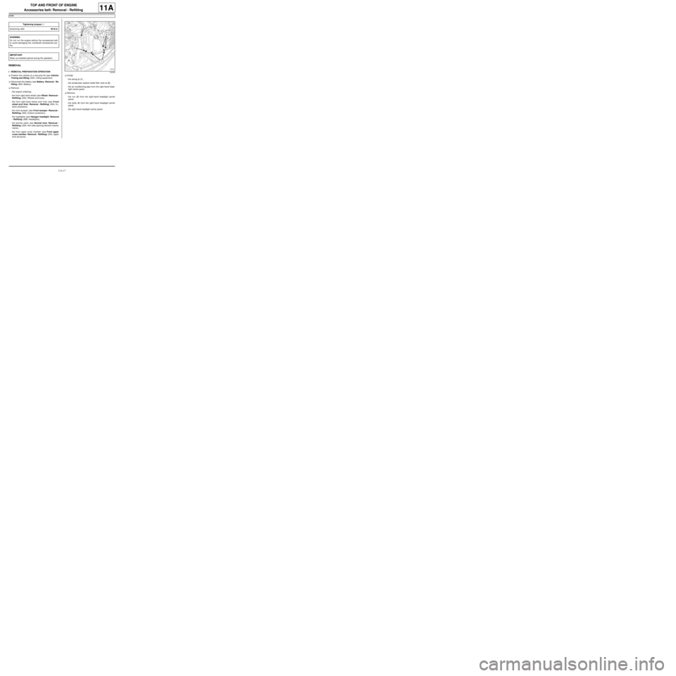
-the wiring at (1) ,
-the windscreen washer bottle filler neck at (2) ,
-the air conditioning pipe from the right-hand head-
light carrier panel.
aRemove:
-the nut (3) from the right-hand headlight carrier
panel,
-the bolts (4) from the right-hand headlight carrier
panel,
-the right-hand headlight carrier panel. Tightening torquesm
tensioning roller40 N.m
WARNING
Do not r un the engine without the accessories belt
to avoid damaging the crankshaft accessories pul-
ley.
IMPORTANT
Wear cut-resistant gloves during the operation.132339
Page 142 of 652
11A-25
TOP AND FRONT OF ENGINE
Crankshaft accessories pulley: Removal - Refitting
K4M
11A
REMOVAL
I - REMOVAL PREPARATION OPERATION
aPosition the vehicle on a two-post lift (see Vehicle:
Towing and lifting) (02A, Lifting equipment).
aDisconnect the battery (see Battery: Removal - Re-
fitting) (80A, Battery).
aRemove:
-the front right-hand wheel (see Wheel: Removal -
Refitting) (35A, Wheels and tyres),
-the engine undertray,
-the front right-hand wheel arch liner (see Front
wheel arch liner: Removal - Refitting) (55A, Ex-
terior protection),
-the front bumper (see Front bumper: Removal -
Refitting) (55A, Exterior protection),
-the headlights (see Halogen headlight: Removal
- Refitting) (80B, Headlights),
-the bonnet catch (see Bonnet lock: Removal -
Refitting) (52A, Non-side opening element mecha-
nisms),
-the front upper cross member (see Front upper
cross member: Removal - Refitting) (42A, Upper
front structure),
-the accessories belt (see 11A, Top and front of
engine, Accessories belt: Removal - Refitting,
page 11A-3) .II - REMOVAL OPERATION
aRemove:
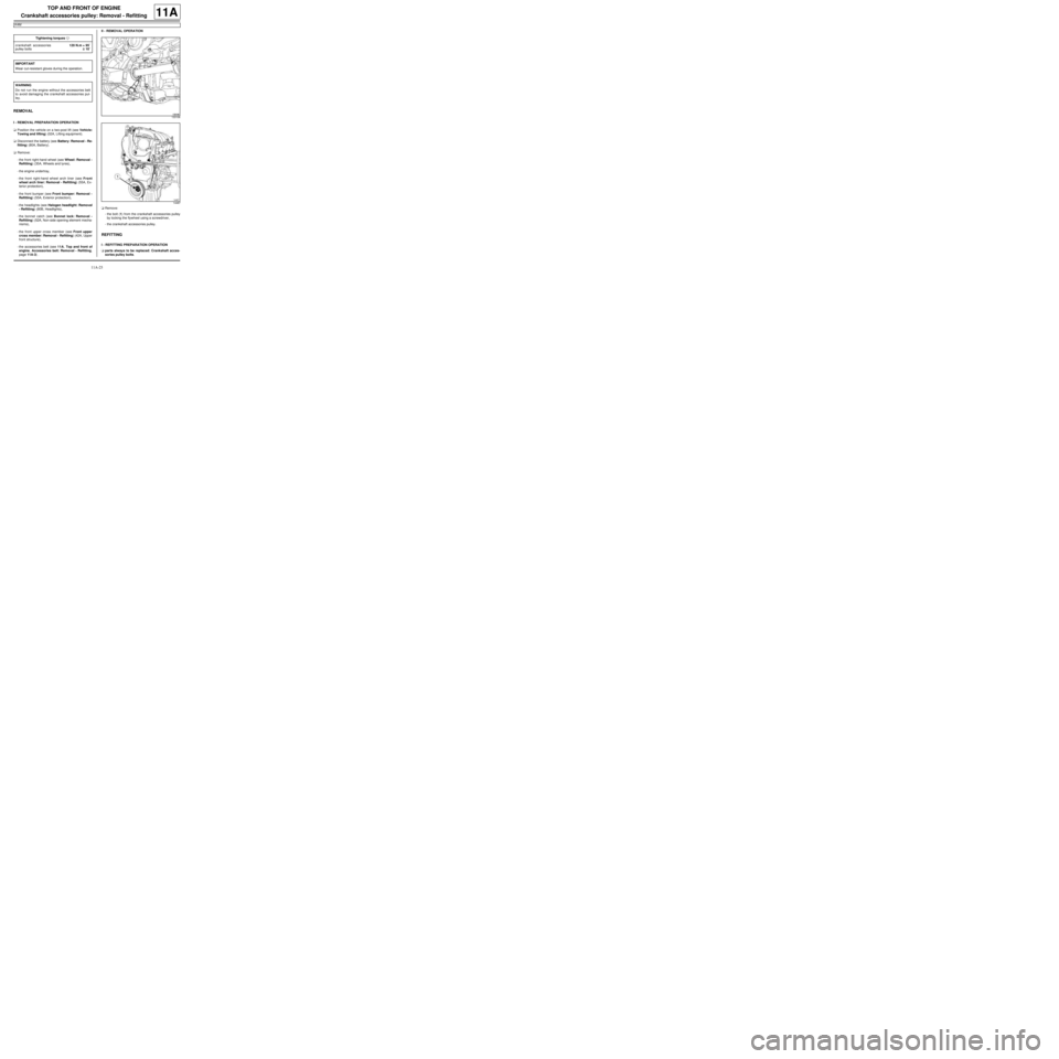
-the bolt (1) from the crankshaft accessories pulley
by locking the flywheel using a screwdriver,
-the crankshaft accessories pulley.
REFITTING
I - REFITTING PREPARATION OPERATION
aparts always to be replaced: Crankshaft acces-
sories pulley bolts. Tightening torquesm
crankshaft accessories
pulley bolts120 N.m + 95˚
±± ± ±
10˚
IMPORTANT
Wear cut-resistant gloves during the operation.
WARNING
Do not r un the engine without the accessories belt
to avoid damaging the crankshaft accessories pul-
ley.
133106
14487
Page 143 of 652
11A-26
TOP AND FRONT OF ENGINE
Crankshaft accessories pulley: Removal - Refitting
K4M
11A
aUse a brush to remove any deposits from the crank-
shaft accessories pulley V grooves.
II - REFITTING OPERATION
aRefit the crankshaft accessories pulley.
aTighten to torque and angle the crankshaft acces-
sories pulley bolts (120 N.m + 95˚ ±± ± ±
10˚) by locking
the engine flywheel using a flat-blade screwdriver.
III - FINAL OPERATION
aRefit:
-the accessories belt (see 11A, Top and front of
engine, Accessories belt: Removal - Refitting,
page 11A-3) .
-the front upper cross member (see Front upper
cross member: Removal - Refitting) (42A, Upper
front structure),
-the bonnet catch (see Bonnet lock: Removal -
Refitting) (52A, Non-side opening element mecha-
nisms),
-the headlights (see Halogen headlight: Removal
- Refitting) (80B, Headlights),
-the front bumper (see Front bumper: Removal -
Refitting) (55A, Exterior protection),
-the front right-hand wheel arch liner (see Front
wheel arch liner: Removal - Refitting) (55A, Ex-
terior protection),
-the engine undertray,
-the front right-hand wheel (see Wheel: Removal -
Refitting) (35A, Wheels and tyres).
aConnect the battery (see Battery: Removal - Refit-
ting) (80A, Battery).
Page 170 of 652
11A-53
TOP AND FRONT OF ENGINE
Timing belt: Removal - Refitting
K4M
11A
REMOVAL
I - REMOVAL PREPARATION OPERATION
aPosition the vehicle on a two-post lift (see Vehicle:
Towing and lifting) (02A, Lifting equipment).
aDisconnect the battery (see Battery: Removal - Re-
fitting) (80A, Battery).
aRemove:
-the engine undertray,
-the front right-hand wheel (see Wheel: Removal -
Refitting) (35A, Wheels and tyres),
-the front right-hand wheel arch liner (see Front
wheel arch liner: Removal - Refitting) (55A, Ex-
terior protection),
-the front bumper (see Front bumper: Removal -
Refitting) (55A, Exterior protection),
-the headlights (see Halogen headlight: Removal
- Refitting) (80B, Headlights),
-the bonnet catch (see Bonnet lock: Removal -
Refitting) (52A, Non-side opening element mecha-
nisms),
-the front upper cross member (see Front upper
cross member: Removal - Refitting) (42A, Upper
front structure),
-the accessories belt (see 11A, Top and front of
engine, Accessories belt: Removal - Refitting,
page 11A-3) ,
-the air filter unit (see 12A, Fuel mixture, Air filter
unit: Removal - Refitting, page 12A-13) ,
-the throttle valve (see 12A, Fuel mixture, Throttle
valve: Removal - Refitting, page 12A-20) ,
-the windscreen wiper arms (see Windscreen wip-
er arm: Removal - Refitting) (85A, Wiping -
Washing),
-the scuttle panel grille (see Scuttle panel grille:
Removal - Refitting) (56A, Exterior equipment), Special tooling required
Mot. 1489TDC locating pin.
Mot. 1368Tool for tightening eccentric
tensioning roller bolt. 8 mm
Torx wrench and 12.7 mm
square.
Mot. 1496Camshaft timing tool.
Mot. 1750Additional tool to suppor t the
camshaft adjusting tool, Mot.
1496.
Mot. 1490-01For locking and adjusting the
camshaft pulle ys.
Mot. 1487Tool for refitting camshaft cov-
ers (57 mm diameter).
Mot. 1488Tool for refitting camshaft cov-
ers (43 mm diameter).
Equipment required
indelible pencil
Tightening torquesm
fixed roller bolt50 N.m
lower timing cover bolts12 N.m
exhaust camshaft pul-
ley nut30 N.m + 84˚
camshaft dephaser pul-
ley bolt100 N.m
timing tension wheel nut27 N.m
TDC setting pin plug20 N.m
upper timing cover bolts41 N.m
upper timing cover nuts41 N.m
rear suspended engine
reinforcement bolt105 N.m
rear suspended engine
mounting bolt on the
rear suspended engine
mounting suppor t105 N.m
rear suspended engine
mounting bolt on the
subframe105 N.m Tightening torquesm
Page 193 of 652
11A-76
TOP AND FRONT OF ENGINE
Rocker cover: Removal - Refitting
K4M
11A
REMOVAL
I - REMOVAL PREPARATION OPERATION
aPosition the vehicle on a two-post lift (see Vehicle:
Towing and lifting) (02A, Lifting equipment).
aDisconnect the battery (see Battery: Removal - Re-
fitting) (80A, Battery).
aRemove:
-the windscreen wiper arms (see Windscreen wip-
er arm: Removal - Refitting) (85A, Wiping -
Washing),
-the scuttle panel grille (see Scuttle panel grille:
Removal - Refitting) (56A, Exterior equipment),
-the scoop under the scuttle panel grille (see Scoop
under the scuttle panel grille: Removal - Refit-
ting) (56A, Exterior equipment),
-the coils (see 17A, Ignition, Coils: Removal - Re-
fitting, page 17A-1) ,
-the throttle valve (see 12A, Fuel mixture, Throttle
valve: Removal - Refitting, page 12A-20) ,
-the inlet distributor (see 12A, Fuel mixture, Inlet
distributor: Removal - Refitting, page 12A-29) ,
-the oil decanter (see 11A, Top and front of en-
gine, Oil decanter: Removal - Refitting, page
11A-147) ,
-the engine undertray,
-the front right-hand wheel (see Wheel: Removal -
Refitting) (35A, Wheels and tyres),
-the front right-hand wheel arch liner (see Front
wheel arch liner: Removal - Refitting) (55A, Ex-
terior protection),-the front bumper (see Front bumper: Removal -
Refitting) (55A, Exterior protection),
-the headlights (see Halogen headlight: Removal
- Refitting) (80B, Headlights),
-the bonnet catch (see Bonnet lock: Removal -
Refitting) (52A, Non-side opening element mecha-
nisms),
-the front upper cross member (see Front upper
cross member: Removal - Refitting) (42A, Upper
front structure),
-the accessories belt (see 11A, Top and front of
engine, Accessories belt: Removal - Refitting,
page 11A-3) ,
-the air filter unit (see 12A, Fuel mixture, Air filter
unit: Removal - Refitting, page 12A-13) ,
-the right-hand suspended engine mounting (see
19D, Engine mounting, Right-hand suspended
engine mounting: Removal - Refitting, page
19D-13) ,
-the crankshaft accessories pulley (see 11A, Top
and front of engine, Crankshaft accessories
pulley: Removal - Refitting, page 11A-20) ,
-the timing belt (see 11A, Top and front of engine,
Timing belt: Removal - Refitting, page 11A-27) ,
-the camshaft dephaser (see 11A, Top and front of
engine, Camshaft dephaser: Removal - Refit-
ting, page 11A-135) ,
-the camshaft seals on the timing end (see 11A,
Top and front of engine, Camshaft seal, timing
end: Removal - Refitting, page 11A-138) . Tightening torquesm
rocker cover bolts 22,
23, 20 and 13 (initial
torque)8 N.m
rocker cover bolts 1 to
12, 14 to 19 and 21 to
2413 N.m
rocker cover bolts 22,
23, 20 and 1313 N.m
camshaft sensor bolt8 N.m
camshaft dephaser
solenoid valve bolt10 N.m
Page 236 of 652
11A-119
TOP AND FRONT OF ENGINE
Cylinder head: Removal - Refitting
K4M
11A
REMOVAL
I - REMOVAL PREPARATION OPERATION
aPosition the vehicle on a two-post lift (see Vehicle:
Towing and lifting) (02A, Lifting equipment).
aDisconnect the battery (see Battery: Removal - Re-
fitting) (80A, Battery).
aRemove the engine undertray.
aDrain the cooling system (see 19A, Cooling, Cool-
ing system: Draining - Refilling, page 19A-9) .
aRemove:
-the windscreen wiper arms (see Windscreen wip-
er arm: Removal - Refitting) (85A, Wiping -
Washing),
-the scuttle panel grille (see Scuttle panel grille:
Removal - Refitting) (56A, Exterior equipment),
-the scoop under the scuttle panel grille (see Scoop
under the scuttle panel grille: Removal - Refit-
ting) (56A, Exterior equipment),
-the coils (see 17A, Ignition, Coils: Removal - Re-
fitting, page 17A-1) ,-the throttle valve (see 12A, Fuel mixture, Throttle
valve: Removal - Refitting, page 12A-20) ,
-the inlet distributor (see 12A, Fuel mixture, Inlet
distributor: Removal - Refitting, page 12A-29) ,
-the oil decanter (see 11A, Top and front of en-
gine, Oil decanter: Removal - Refitting, page
11A-147) ,
-the front right-hand wheel (see Wheel: Removal -
Refitting) (35A, Wheels and tyres),
-the front right-hand wheel arch liner (see Front
wheel arch liner: Removal - Refitting) (55A, Ex-
terior protection),
-the front bumper (see Front bumper: Removal -
Refitting) (55A, Exterior protection),
-the headlights (see Halogen headlight: Removal
- Refitting) (80B, Headlights),
-the bonnet catch (see Bonnet lock: Removal -
Refitting) (52A, Non-side opening element mecha-
nisms),
-the front upper cross member (see Front upper
cross member: Removal - Refitting) (42A, Upper
front structure),
-the accessories belt (see 11A, Top and front of
engine, Accessories belt: Removal - Refitting,
page 11A-3) ,
-the air filter unit (see 12A, Fuel mixture, Air filter
unit: Removal - Refitting, page 12A-13) ,
-the lower engine tie-bar (see 19D, Engine mount-
ing, Lower engine tie-bar: Removal - Refitting,
page 19D-18) ,
-the right-hand suspended engine mounting (see
19D, Engine mounting, Right-hand suspended
engine mounting: Removal - Refitting, page
19D-13) ,
-the crankshaft accessories pulley (see 11A, Top
and front of engine, Crankshaft accessories
pulley: Removal - Refitting, page 11A-20) ,
-the timing belt (see 11A, Top and front of engine,
Timing belt: Removal - Refitting, page 11A-27) ,
-the camshaft dephaser (see 11A, Top and front of
engine, Camshaft dephaser: Removal - Refit-
ting, page 11A-135) ,
-the camshaft seals on the timing end (see 11A,
Top and front of engine, Camshaft seal, timing
end: Removal - Refitting, page 11A-138) ,
-the rocker cover (see 11A, Top and front of en-
gine, Rocker cover: Removal - Refitting, page
11A-66) , Special tooling required
Mot. 1448Remote operation pliers for
hose clips .
Mot. 1202-01Clip pliers for hose clips
(large size).
Mot. 1202-02Clip pliers for hose clips
(small size)
Tightening torquesm
cylinder head bolts (ini-
tial torque)20 N.m
cylinder head bolts240˚ ±± ± ±
6˚
IMPORTANT
Wear cut-resistant gloves during the operation.
IMPORTANT
Wear leaktight gloves (Nitrile type) for this opera-
tion.