Undertray bolts RENAULT TWINGO RS 2009 2.G Engine And Peripherals Workshop Manual
[x] Cancel search | Manufacturer: RENAULT, Model Year: 2009, Model line: TWINGO RS, Model: RENAULT TWINGO RS 2009 2.GPages: 652
Page 19 of 652
10A-13
ENGINE AND CYLINDER BLOCK ASSEMBLY
Lower cover: Removal - Refitting
D4F or D7F
10A
REMOVAL
I - REMOVAL PREPARATION OPERATION
aPosition the vehicle on a two-post lift (see Vehicle:
Towing and lifting) (02A, Lifting equipment).
aDrain the engine oil (see 10A, Engine and cylinder
block assembly, Engine oil: Draining - Refilling,
page 10A-22) .
aRemove the engine undertray.
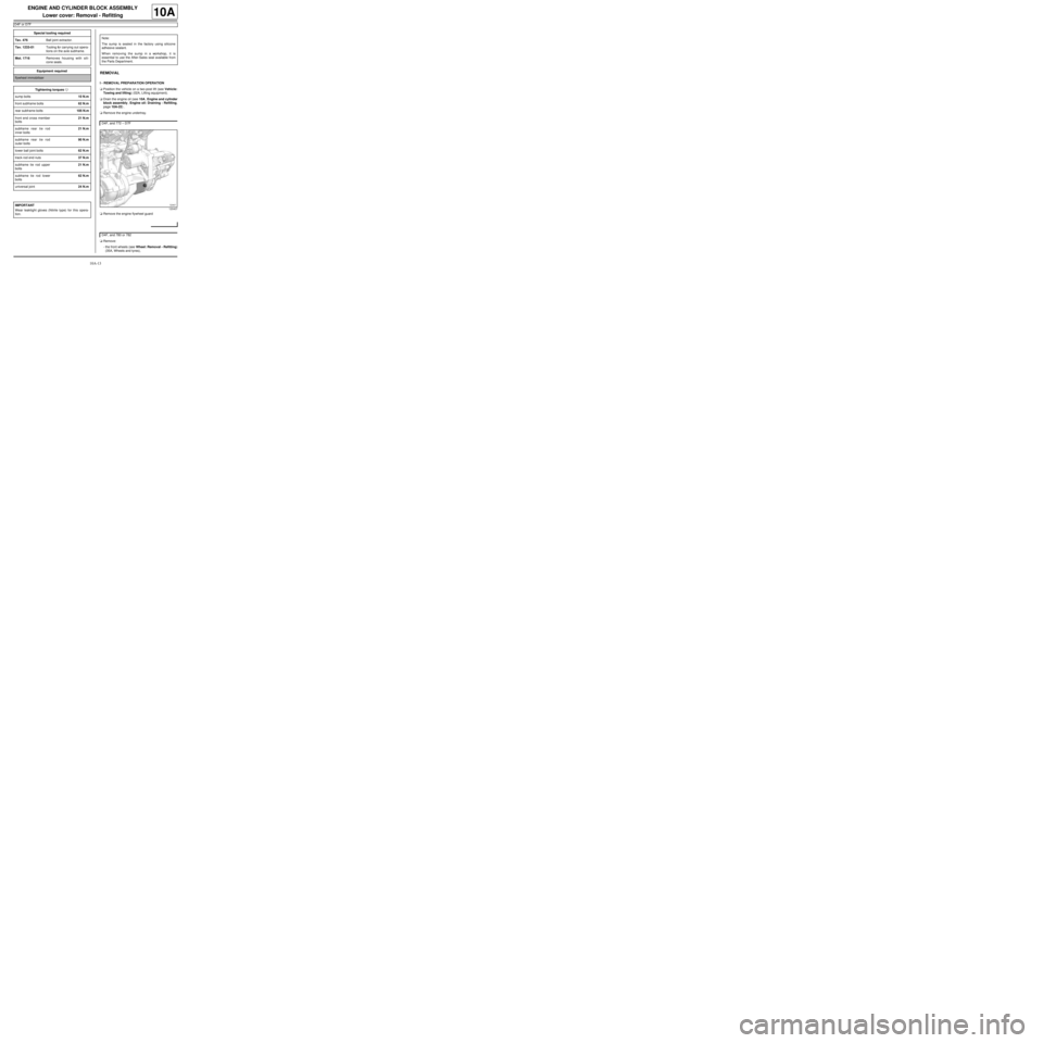
aRemove the engine flywheel guard
aRemove:
-the front wheels (see Wheel: Removal - Refitting)
(35A, Wheels and tyres), Special tooling required
Tav. 476Ball joint extractor.
Tav. 1233-01Tooling for carrying out opera-
tions on the axle subframe.
Mot. 1716Removes housing with sili-
cone seals.
Equipment required
flywheel immobiliser
Tightening torquesm
sump bolts10 N.m
front subframe bolts62 N.m
rear subframe bolts105 N.m
front end cross member
bolts21 N.m
subframe rear tie rod
inner bolts21 N.m
subframe rear tie rod
outer bolts90 N.m
lower ball joint bolts62 N.m
track rod end nuts37 N.m
subframe tie rod upper
bolts21 N.m
subframe tie rod lower
bolts62 N.m
universal joint24 N.m
IMPORTANT
Wear leaktight gloves (Nitrile type) for this opera-
tion.
Note:
The sump is sealed in the factory using silicone
adhesive sealant.
When removing the sump in a workshop, it is
essential to use the After-Sales seal available from
the Parts Department.
D4F, and 772 – D7F
120407
D4F, and 780 or 782
Page 24 of 652
10A-18
ENGINE AND CYLINDER BLOCK ASSEMBLY
Lower cover: Removal - Refitting
K4M
10A
REMOVAL
I - REMOVAL PREPARATION OPERATION
aPosition the vehicle on a two-post lift (see Vehicle:
Towing and lifting) (02A, Lifting equipment).
aRemove:
-the dipstick,
-the front wheels (see Wheel: Removal - Refitting)
(35A, Wheels and tyres),
-the engine undertray.
aDrain the engine oil (see 10A, Engine and cylinder
block assembly, Engine oil: Draining - Refilling,
page 10A-22) .
aRemove:
-the front wheel arch liners (see Front wheel arch
liner: Removal - Refitting) (55A, Exterior protec-
tion),
-the front bumper (see Front bumper: Removal -
Refitting) (55A, Exterior protection),-the rear engine tie-bar (see 19D, Engine mount-
ing, Lower engine tie-bar: Removal - Refitting,
page 19D-18) ,
-the front axle subframe (see Front axle subframe:
Removal - Refitting) (31A, Front axle compo-
nents).
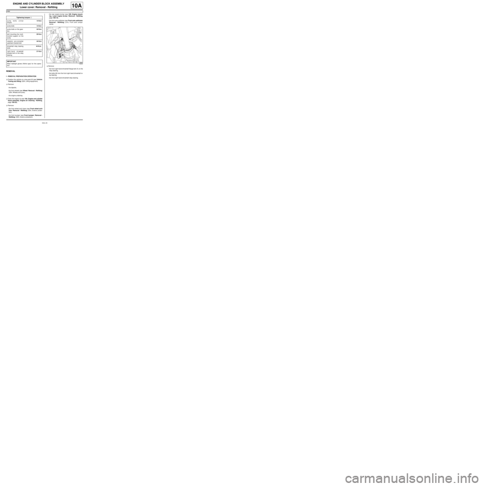
aRemove:
-the front right-hand driveshaft flange bolt (1) on the
relay bearing,
-the bolts (2) from the front right-hand driveshaft re-
lay bearing,
-the front right-hand driveshaft relay bearing. Tightening torquesm
sump bolts (initial
torque)14 N.m
sump bolts14 N.m
sump bolts on the gear-
box44 N.m
bolt mounting the multi-
function support on the
sump25 N.m
catalytic pre-converter
upstream bracket bolt44 N.m
driveshaft relay bearing
bolts44 N.m.
right-hand driveshaft
bracket bolt on the relay
bearing21 N.m
IMPORTANT
Wear leaktight gloves (Nitrile type) for this opera-
tion.
128800
Page 27 of 652
10A-21
ENGINE AND CYLINDER BLOCK ASSEMBLY
Lower cover: Removal - Refitting
K4M
10A
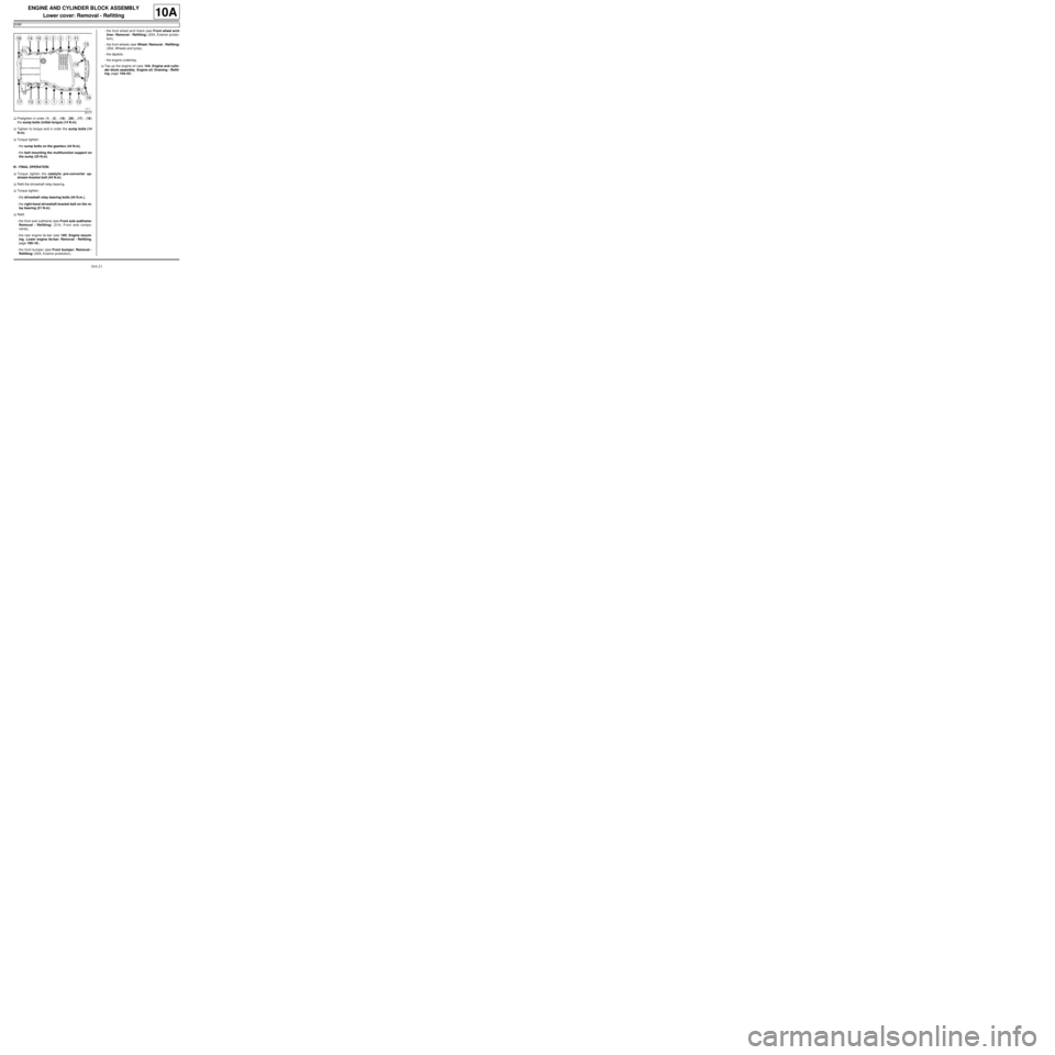
aPretighten in order (1) , (2) , (19) , (20) , (17) , (18)
the sump bolts (initial torque) (14 N.m).
aTighten to torque and in order the sump bolts (14
N.m).
aTorque tighten:
-the sump bolts on the gearbox (44 N.m),
-the bolt mounting the multifunction support on
the sump (25 N.m).
III - FINAL OPERATION
aTorque tighten the catalytic pre-converter up-
stream bracket bolt (44 N.m).
aRefit the driveshaft relay bearing.
aTorque tighten:
-the driveshaft relay bearing bolts (44 N.m.),
-the right-hand driveshaft bracket bolt on the re-
lay bearing (21 N.m).
aRefit:
-the front axle subframe (see Front axle subframe:
Removal - Refitting) (31A, Front axle compo-
nents),
-the rear engine tie-bar (see 19D, Engine mount-
ing, Lower engine tie-bar: Removal - Refitting,
page 19D-18) ,
-the front bumper (see Front bumper: Removal -
Refitting) (55A, Exterior protection),-the front wheel arch liners (see Front wheel arch
liner: Removal - Refitting) (55A, Exterior protec-
tion),
-the front wheels (see Wheel: Removal - Refitting)
(35A, Wheels and tyres),
-the dipstick,
-the engine undertray.
aTop up the engine oil (see 10A, Engine and cylin-
der block assembly, Engine oil: Draining - Refill-
ing, page 10A-22) .
20171
Page 32 of 652
10A-26
ENGINE AND CYLINDER BLOCK ASSEMBLY
Engine oil: Draining - Refilling
K4M
10A
III - DRAINING
aPosition the vehicle on a two-post lift (see Vehicle:
Towing and lifting) (02A, Lifting equipment).
aRemove:
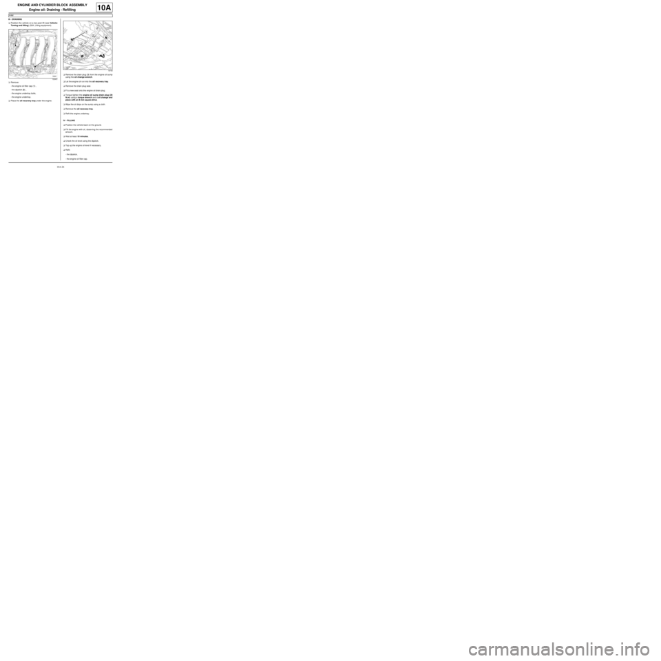
-the engine oil filler cap (1) ,
-the dipstick (2) ,
-the engine undertray bolts,
-the engine undertray.
aPlace the oil recovery tray under the engine.aRemove the drain plug (3) from the engine oil sump
using the oil change wrench.
aLet the engine oil run into the oil recovery tray.
aRemove the drain plug seal.
aFit a new seal onto the engine oil drain plug.
aTorque tighten the engine oil sump drain plug (20
N.m) using a torque wrench and a oil change end
piece with an 8 mm square drive.
aWipe the oil drips on the sump using a cloth.
aRemove the oil recovery tray.
aRefit the engine undertray.
IV - FILLING
aPosition the vehicle back on the ground.
aFill the engine with oil, observing the recommended
amount.
aWait at least 10 minutes.
aCheck the oil level using the dipstick.
aTop up the engine oil level if necessary.
aRefit:
-the dipstick,
-the engine oil filler cap.
132431
18749
Page 34 of 652
10A-28
ENGINE AND CYLINDER BLOCK ASSEMBLY
Engine oil: Draining - Refilling
K9K
10A
III - OIL SERVICE
aPosition the vehicle on a two-post lift (see Vehicle:
Towing and lifting) (02A, Lifting equipment).
aRemove:
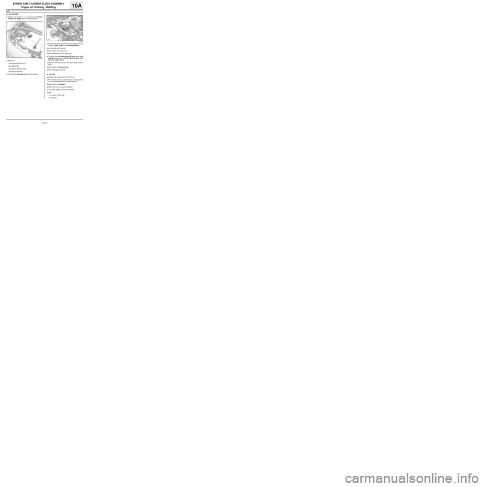
-the engine oil filler cap (1) ,
-the dipstick (2) ,
-the engine undertray bolts,
-the engine undertray.
aPlace the oil recovery tray under the engine.aRemove the drain plug (3) from the engine oil sump
using the (Mot. 1018) or a oil change wrench.
aLet the engine oil flow out.
aRemove the drain plug seal.
aRefit the new seal to the drain plug.
aTorque tighten the drain plug (20 N.m) using a oil
change wrench and a oil change end piece with
an 8 mm square drive.
aWipe the oil drips around the drain plug using a
cloth.
aRemove the oil recovery tray.
aRefit the engine undertray.
IV - FILLING
aPosition the vehicle back on the ground.
aFill the engine with oil, observing the correct quantity
of oil as recommended by the manufacturer.
aWait at least 10 minutes.
aCheck the oil level using the dipstick.
aTop up the engine oil level if necessary.
aRefit:
-the engine oil filler cap,
-the dipstick.
120041
120042
Page 43 of 652
10A-37
ENGINE AND CYLINDER BLOCK ASSEMBLY
Conrod bearing shell: Removal - Refitting
K9K
10A
REMOVAL
I - REMOVAL PREPARATION OPERATION
aPosition the vehicle on a two-post lift (see Vehicle:
Towing and lifting) (02A, Lifting equipment).
aRemove the engine undertray.
aDrain the oil from the engine (see 10A, Engine and
cylinder block assembly, Engine oil: Draining -
Refilling, page 10A-22) .
aRemove the oil filter (see 10A, Engine and cylinder
block assembly, Oil filter: Removal - Refitting,
page 10A-29) .
aRemove the lower engine tie-bar (see 19D, Engine
mounting, Lower engine tie-bar: Removal - Refit-
ting, page 19D-18) .
aStrap the radiator to the vehicle using safety
strap(s).
aRemove the front axle subframe (see Front axle
subframe: Removal - Refitting) (31A, Front axle
components).
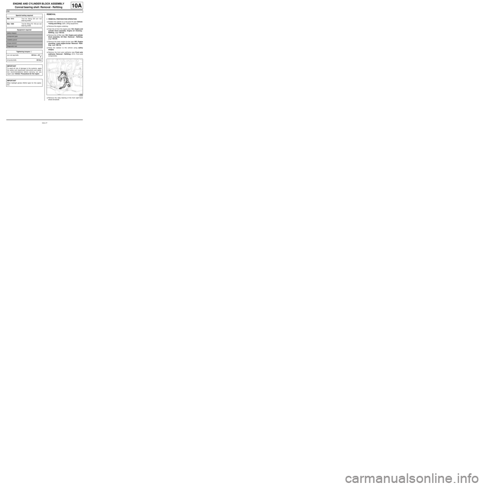
aRemove the relay bearing of the front right-hand
wheel driveshaft. Special tooling required
Mot. 1914Tool for fitting G9 con rod
bear ing shells
Mot. 1920Tool for fitting F9 / K9 con rod
bear ing shells
Equipment required
safety strap(s)
component jack
indelible pencil
torque wrench
Diagnostic tool
Tightening torquesm
con rod cap bolts20 N.m + 45˚ ±± ± ±
6˚
oil pump bolts25 N.m
IMPORTANT
To avoid all risk of damage to the systems, apply
the safety and cleanliness instructions and opera-
tion recommendations before carrying out any
repair (see Vehicle: Precautions for the repair) .
IMPORTANT
Wear leaktight gloves (Nitrile type) for this opera-
tion.
123838
Page 50 of 652
10A-44
ENGINE AND CYLINDER BLOCK ASSEMBLY
Conrod bearing shell: Removal - Refitting
K9K
10A
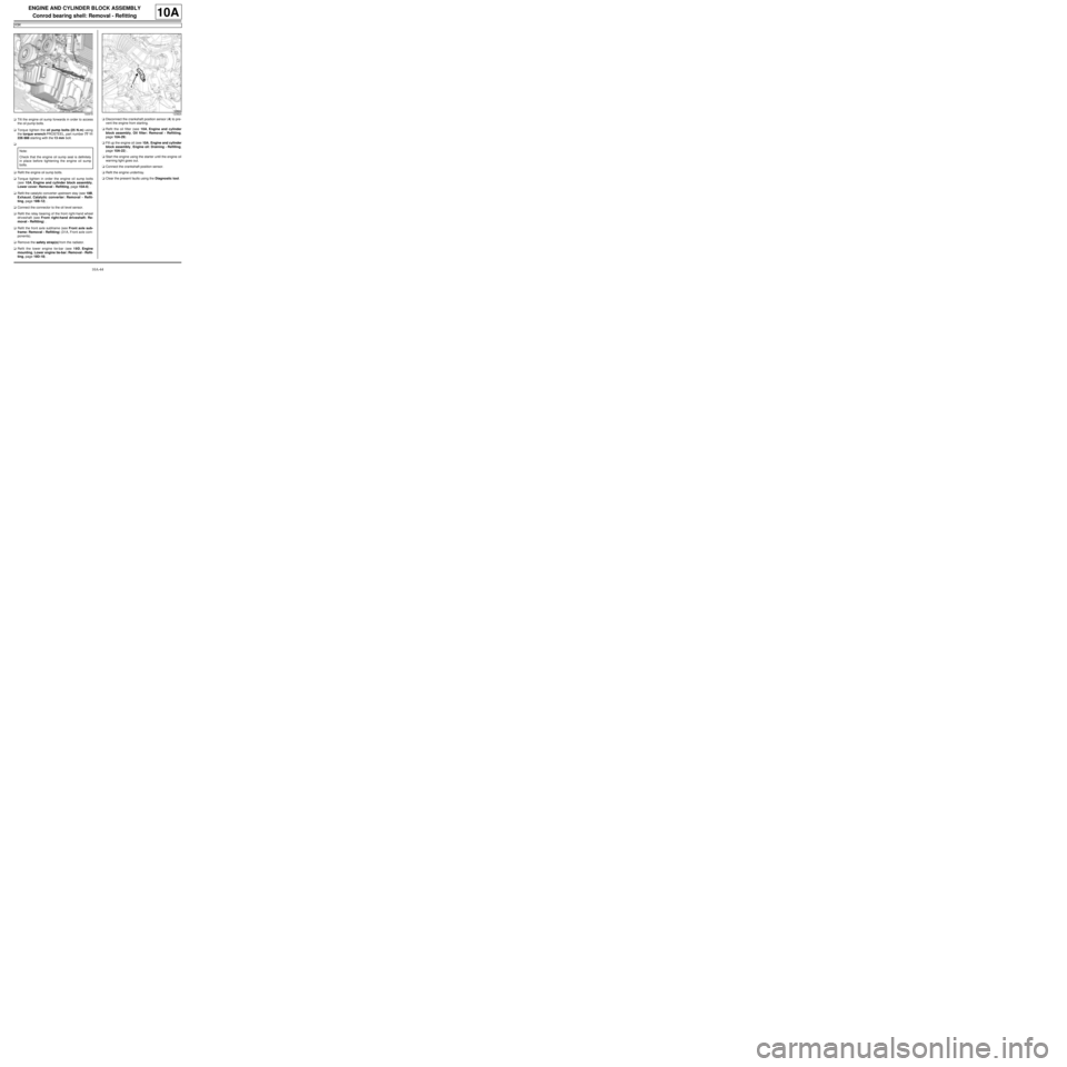
aTilt the engine oil sump forwards in order to access
the oil pump bolts.
aTorque tighten the oil pump bolts (25 N.m) using
the torque wrench PROSTEEL, part number 77 11
226 888 starting with the 13 mm bolt.
a
aRefit the engine oil sump bolts.
aTorque tighten in order the engine oil sump bolts
(see 10A, Engine and cylinder block assembly,
Lower cover: Removal - Refitting, page 10A-6) .
aRefit the catalytic converter upstream stay (see 19B,
Exhaust, Catalytic converter: Removal - Refit-
ting, page 19B-12) .
aConnect the connector to the oil level sensor.
aRefit the relay bearing of the front right-hand wheel
driveshaft (see Front right-hand driveshaft: Re-
moval - Refitting) .
aRefit the front axle subframe (see Front axle sub-
frame: Removal - Refitting) (31A, Front axle com-
ponents).
aRemove the safety strap(s) from the radiator.
aRefit the lower engine tie-bar (see 19D, Engine
mounting, Lower engine tie-bar: Removal - Refit-
ting, page 19D-18) .aDisconnect the crankshaft position sensor (4) to pre-
vent the engine from starting.
aRefit the oil filter (see 10A, Engine and cylinder
block assembly, Oil filter: Removal - Refitting,
page 10A-29)
aFill up the engine oil (see 10A, Engine and cylinder
block assembly, Engine oil: Draining - Refilling,
page 10A-22) .
aStart the engine using the starter until the engine oil
warning light goes out.
aConnect the crankshaft position sensor.
aRefit the engine undertray.
aClear the present faults using the Diagnostic tool.
140918
Note:
Check that the engine oil sump seal is definitely
in place before tightening the engine oil sump
bolts.
123824
Page 62 of 652
10A-56
ENGINE AND CYLINDER BLOCK ASSEMBLY
Oil pump: Removal - Refitting
D4F or D7F
10A
aRemove:
-the nut,
-the cover,
-the guard,
-the threaded rod.
aConnect the oil-coolant heat exchanger hoses.
aPut the clips (3) in place using the (Mot. 1448).
aRemove the hose clamps (Ms. 583) from the oil-wa-
ter heat exchanger hoses.
aConnect the oil pressure sensor connector.
aRefit:
-the timing sprocket,
-the sump (see 10A, Engine and cylinder block
assembly, Lower cover: Removal - Refitting,
page 10A-6) .
aFit the lower engine support tool (Mot. 1379).
aRemove:
-the right-hand suspended mounting support bolts,
-the right-hand suspended mounting support,
-the upper timing cover bolts,
-the upper timing cover.aRefit:
-the timing belt (see 11A, Top and front of engine,
Timing belt: Removal - Refitting, page 11A-27) ,
-the crankshaft accessories pulley (see 11A, Top
and front of engine, Crankshaft accessories
pulley: Removal - Refitting, page 11A-20) ,
-the right-hand suspended engine mounting (see
19D, Engine mounting, Right-hand suspended
engine mounting: Removal - Refitting, page
19D-13) .
aRemove the lower engine support tool (Mot. 1379).
aRefit:
-the engine tie-bar (see 19D, Engine mounting,
Lower engine tie-bar: Removal - Refitting, page
19D-18) ,
-the accessories belt (see 11A, Top and front of
engine, Accessories belt: Removal - Refitting,
page 11A-3) ,
-the engine undertray,
-the front wheel arch liners (see Front wheel arch
liner: Removal - Refitting) (55A, Exterior protec-
tion),
-the front wheels (see Wheel: Removal - Refitting)
(35A, Wheels and tyres),
-the dipstick,
-the oil filter (see 10A, Engine and cylinder block
assembly, Oil filter: Removal - Refitting, page
10A-29) .
aTop up the engine oil (see 10A, Engine and cylin-
der block assembly, Engine oil: Draining - Refill-
ing, page 10A-22) .
aTop up the coolant level (see 19A, Cooling, Cool-
ing system: Draining - Refilling, page 19A-9) .
20779
D4F, and 780 or 782
Page 63 of 652
10A-57
ENGINE AND CYLINDER BLOCK ASSEMBLY
Oil pump: Removal - Refitting
K4M
10A
REMOVAL
I - REMOVAL PREPARATION OPERATION
aPosition the vehicle on a two-post lift (see Vehicle:
Towing and lifting) (02A, Lifting equipment).
aRemove:
-the front wheels (see Wheel: Removal - Refitting)
(35A, Wheels and tyres),
-the engine undertray.
aDrain the engine oil (see 10A, Engine and cylinder
block assembly, Engine oil: Draining - Refilling,
page 10A-22) .
aRemove:
-the front wheel arch liners (see Front wheel arch
liner: Removal - Refitting) (55A, Exterior protec-
tion),
-the front bumper (see Front bumper: Removal -
Refitting) (55A, Exterior protection),
-the rear engine tie-bar (see 19D, Engine mount-
ing, Lower engine tie-bar: Removal - Refitting,
page 19D-18) ,
-the front axle subframe (see Front axle subframe:
Removal - Refitting) (31A, Front axle compo-
nents).
aRemove the sump (see 10A, Engine and cylinder
block assembly, Lower cover: Removal - Refit-
ting, page 10A-6) .II - REMOVAL OPERATION
aRemove:
-the oil pump bolts (1) ,
-the oil pump.
REFITTING
I - REFITTING OPERATION
aPosition the oil pump pinion on the chain.
aRefit the oil pump.
aTorque tighten the oil pump bolts (25 N.m).
II - FINAL OPERATION
aRefit the sump (see 10A, Engine and cylinder
block assembly, Lower cover: Removal - Refit-
ting, page 10A-6) .
aRefit:
-the front axle subframe (see Front axle subframe:
Removal - Refitting) (31A, Front axle compo-
nents),
-the rear engine tie-bar (see 19D, Engine mount-
ing, Lower engine tie-bar: Removal - Refitting,
page 19D-18) ,
-the front bumper (see Front bumper: Removal -
Refitting) (55A, Exterior protection),
-the front wheel arch liners (see Front wheel arch
liner: Removal - Refitting) (55A, Exterior protec-
tion), Tightening torquesm
oil pump bolts25 N.m
128799
Page 77 of 652
10A-71
ENGINE AND CYLINDER BLOCK ASSEMBLY
Multifunction support: Removal - Refitting
K4M
10A
REMOVAL
I - REMOVAL PREPARATION OPERATION
aPosition the vehicle on a two-post lift (see Vehicle:
Towing and lifting) (02A, Lifting equipment).
aDisconnect the battery (see Battery: Removal - Re-
fitting) (80A, Battery).
aRemove the engine undertray.
aDrain the refrigerant circuit using a refrigerant
charging station (see Refrigerant circuit: Drain-
ing - Filling) (62A, Air conditioning).
aRemove:
-the front right-hand wheel (see Wheel: Removal -
Refitting) (35A, Wheels and tyres),
-the front right-hand wheel arch liner (see Front
wheel arch liner: Removal - Refitting) (55A, Ex-
terior protection),
-the front bumper (see Front bumper: Removal -
Refitting) (55A, Exterior protection),
-the headlights (see Halogen headlight: Removal
- Refitting) (80B, Headlights),
-the bonnet catch (see Bonnet lock: Removal -
Refitting) (52A, Non-side opening element mecha-
nisms),-the front upper cross member (see Front upper
cross member: Removal - Refitting) (42A, Upper
front structure),
-the accessories belt (see 11A, Top and front of
engine, Accessories belt: Removal - Refitting,
page 11A-3) ,
-the alternator (see 16A, Starting - Charging, Al-
ternator: Removal - Refitting, page 16A-1) ,
-the air conditioning compressor (see Compressor:
Removal - Refitting) (62A, Air conditioning). Equipment required
refrigerant charging station
Tightening torquesm
multifunction support
bolts 1 and 2 (initial
torque)5 N.m
multifunction support
bolt 7 on the cylinder
block (initial torque)5 N.m
multifunction support
bolts 6, 5, 4 and 35 N.m
multifunction support
bolts44 N.m
multifunction support
bolt on the cylinder
block25 N.m