ABS RENAULT TWINGO RS 2009 2.G Engine And Peripherals Owner's Manual
[x] Cancel search | Manufacturer: RENAULT, Model Year: 2009, Model line: TWINGO RS, Model: RENAULT TWINGO RS 2009 2.GPages: 652
Page 431 of 652
14A-13
ANTIPOLLUTION
Exhaust gas cooler: Removal - Refitting
K9K
14A
II - REFITTING OPERATION FOR PART
CONCERNED
aOn the workbench, refit the following to the intercoo-
ler:
-a new mounting seal on the gearbox side,
-the mounting on the gearbox side,
-the mounting bolts (gearbox side) onto the inter-
cooler without tightening them,
-a new exhaust gas recirculation rigid pipe,
-the bolts of the exhaust gas recirculation rigid pipe
bracket on the cooler without tightening them.
aFit the exhaust gas recirculation assembly onto the
cylinder head.
aAdjust the mounting (gearbox side) and the exhaust
gas recirculation rigid pipe until they are flat against
the cylinder head.
aFit the exhaust gas recirculation unit assembly bolts,
without tightening them.
aTighten the bolts of the mounting (gearbox side) and
of the exhaust gas recirculation rigid pipe on the ex-
haust gas cooler to secure them on the exhaust gas
cooler.
aRemove the exhaust gas recirculation assembly.
aOn the workbench, torque tighten:
-the mounting bolts (gearbox side) on the cooler
(12 N.m),
-the bolts of the exhaust gas recirculation rigid
pipe on the exhaust gas cooler (12 N.m),
-the bolts of the exhaust gas recirculation rigid
pipe bracket (25 N.m).aOn the workbench, refit the following to the intercoo-
ler:
-a new mounting seal on the gearbox side,
-the mounting on the gearbox side,
-the mounting bolts (gearbox side) onto the inter-
cooler without tightening them,
-a new mounting seal on the timing end,
-the mounting on the timing end,
-the mounting bolts (timing end) onto the intercooler
without tightening them.
aFit the exhaust gas recirculation assembly onto the
cylinder head.
aAdjust the two mountings until they are flat against
the cylinder head.
aFit the exhaust gas recirculation unit assembly bolts,
without tightening them.
aTighten the bolts of the two mountings on the ex-
haust gas cooler to immobilise them on the exhaust
gas cooler.
aRemove the exhaust gas recirculation assembly.
aOn the workbench, torque tighten the mounting
bolts on the cooler (12 N.m).
III - FINAL OPERATION
aRefit the exhaust gas recirculation assembly (see
14A, Antipollution, Exhaust gas recirculation as-
sembly: Removal - Refitting, page 14A-15) . K9K, and 718
Note:
The cooler must absolutely be able to move in
relation to the mounting (gearbox side) and to the
exhaust gas recirculation rigid pipe so that it can
be properly adjusted afterwards on the cylinder
head.
K9K, and 740
Note:
The cooler must absolutely be able to move in
relation to its tw o mountings so that it can be
properly adjusted afterwards on the cylinder
head.
Page 484 of 652
17B-9
PETROL INJECTION
Petrol injection: List and location of components
K4M
17B
131776
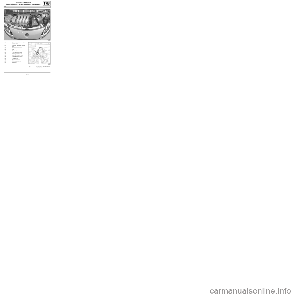
(1) Fuel vapour absorber bleed
solenoid valve
(2) Camshaft dephaser solenoid
valve
(3) Air inlet pressure sensor
(4) Coil
(5) Throttle valve
(6) Petrol injection computer
(7) Switching protection unit
(8) Coolant temper ature sensor
(9) Camshaft position sensor
(10) Pinking sensor
(11) Oil pressure sensor
(12) Air temperature sensor
(13) Injector rail
131766
(1) Fuel vapour absorber bleed
solenoid valve
Page 561 of 652
19A-51
COOLING
Engine cooling fan assembly: Removal - Refitting
C44, and K9K
19A
REMOVAL
I - REMOVAL PREPARATION OPERATION
aPosition the vehicle on a two-post lift ( (see Vehicle:
Towing and lifting) )
aDisconnect the battery ( (see Battery: Removal -
Refitting) ).
aRemove:
-the engine undertray bolts,
-the engine undertray,
-the front bumper ( (see Front bumper: Removal -
Refitting) ),
-the left-hand and right-hand headlights (see Halo-
gen headlight: Removal - Refitting) .
aRemove:
-the cooling radiator retaining lug bolt,
-the expansion bottle bolt onto the front upper cross
member,
-the air filter inlet air pipe bolt on the front upper
cross member.
aUnclip and then remove from the front upper cross
member:
-the air filter inlet air pipe,
-the expansion bottle.
aRemove the bonnet lock nuts.
aRemove the « cable - bonnet catch » assembly.
aRemove the front upper cross member ( (see Front
upper cross member: Removal - Refitting) )
II - OPERATION FOR REMOVAL OF PART
CONCERNED
aDisconnect the electrical connectors on the engine
cooling fan assembly.
aUnclip:
-the engine cooling fan assembly wiring,
-the coolant hose at the bottom of the engine cool-
ing fan assembly.aPress on the engine cooling fan assembly locking
tabs (1) on the cooling radiator.
Note:
Do not unclip the bonnet release cable to avoid
damaging the cable clip on the lock.
AIR CONDITIONING
120324
Note:
Be careful not to press too hard on the tabs to
avoid breaking them.
Page 562 of 652
19A-52
COOLING
Engine cooling fan assembly: Removal - Refitting
C44, and K9K
19A
aPress on the engine cooling fan assembly locking
tabs (2) on the cooling radiator.
aWithdraw the engine cooling fan assembly from the
cooling radiator from above, while pressing on the
locking tabs.
REFITTING
I - REFITTING OPERATION FOR PART
CONCERNED
aFit the engine cooling fan assembly to the cooling ra-
diator.
aClip the engine cooling fan assembly to the cooling
radiator.
aConnect the electrical connectors to the engine cool-
ing fan assembly.aClip:
-the engine cooling fan assembly wiring in place,
-the coolant hose at the bottom of the engine cool-
ing fan assembly.
II - FINAL OPERATION
aRefitting the front upper cross member (see MR 412
Bodywork, 42A, Upper front structure, Cross
member: Removal - Refitting).
aFit the « cable - bonnet catch » assembly.
aRefit the bonnet catch nuts.
aClip and move away from the front upper cross
member:
-the expansion bottle,
-the air filter inlet air pipe.
aRefit:
-the air filter inlet air pipe bolt onto the front upper
cross member,
-the expansion bottle bolt onto the front upper cross
member,
-the cooling radiator retaining lug bolt.
aTighten on the front upper cross member:
-the air filter inlet air pipe bolt onto the front upper
cross member,
-the expansion bottle bolt onto the front upper cross
member,
-the cooling radiator retaining lug bolt.
aRefit:
-the left-hand and right-hand headlights (see 80B,
Headlights, Halogen headlights: Removal - Re-
fitting),
-the front bumper ( (see Front bumper: Removal -
Refitting) ),
-the engine undertray,
-the engine undertray bolts.
aTighten the engine undertray bolts until contact is
made.
aConnect the battery ( (see Battery: Removal - Re-
fitting) ). STANDARD HEATING
120325
Note:
Be careful not to press too hard on the tabs to
avoid breaking them.
Note:
Check that the tabs lock the engine cooling fan
assembly on the cooling radiator correctly.
Page 565 of 652
19A-55
COOLING
Engine cooling fan assembly: Removal - Refitting
D4F, and 780 or 782
19A
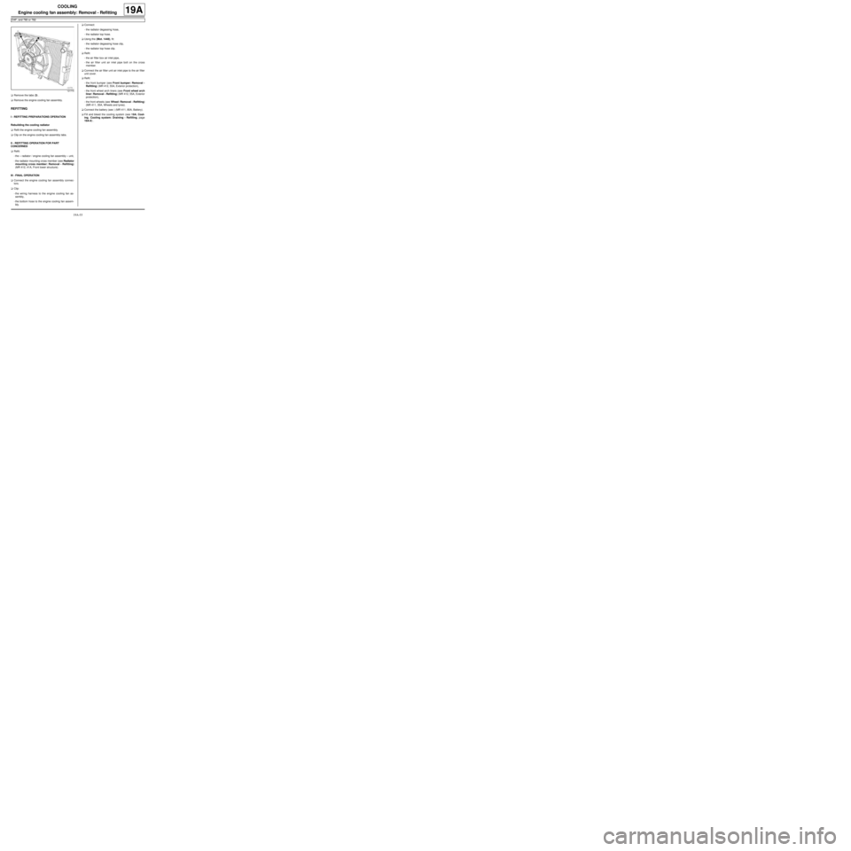
aRemove the tabs (3) .
aRemove the engine cooling fan assembly.
REFITTING
I - REFITTING PREPARATIONS OPERATION
Rebuilding the cooling radiator
aRefit the engine cooling fan assembly.
aClip on the engine cooling fan assembly tabs.
II - REFITTING OPERATION FOR PART
CONCERNED
aRefit:
-the « radiator / engine cooling fan assembly » unit,
-the radiator mounting cross member (see Radiator
mounting cross member: Removal - Refitting)
(MR 412, 41A, Front lower structure).
III - FINAL OPERATION
aConnect the engine cooling fan assembly connec-
tors.
aClip:
-the wiring harness to the engine cooling fan as-
sembly,
-the bottom hose to the engine cooling fan assem-
bly.aConnect:
-the radiator degassing hose,
-the radiator top hose.
aUsing the (Mot. 1448), fit:
-the radiator degassing hose clip,
-the radiator top hose clip.
aRefit:
-the air filter box air inlet pipe,
-the air filter unit air inlet pipe bolt on the cross
member.
aConnect the air filter unit air inlet pipe to the air filter
unit cover.
aRefit:
-the front bumper (see Front bumper: Removal -
Refitting) (MR 412, 55A, Exterior protection),
-the front wheel arch liners (see Front wheel arch
liner: Removal - Refitting) (MR 412, 55A, Exterior
protection),
-the front wheels (see Wheel: Removal - Refitting)
(MR 411, 35A, Wheels and tyres).
aConnect the battery (see ) (MR 411, 80A, Battery).
aFill and bleed the cooling system (see 19A, Cool-
ing, Cooling system: Draining - Refilling, page
19A-9) .
121770
Page 621 of 652
19C-7
TANK
Fuel tank: Removal - Refitting
D4F or D7F or K4M or K9K
19C
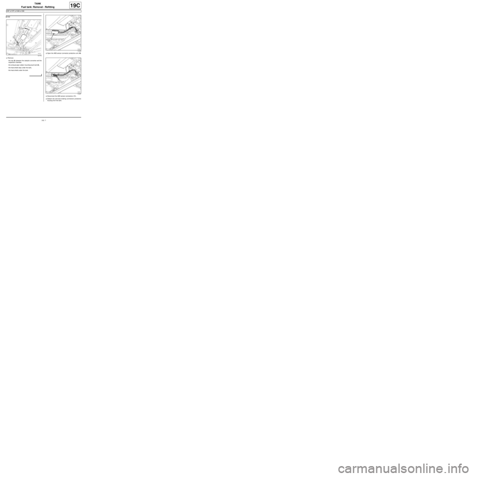
aRemove:
-the clip (8) between the catalytic converter and the
expansion chamber,
-the exhaust pipe rubber mounting bush bolt (9) ,
-the heat shield clips under the tank,
-the heat shield under the tank.aOpen the ABS sensor connector protective unit (10)
.
aDisconnect the ABS sensor connectors (11) .
aDetach the anti-lock braking connectors protective
housing from the tank. K4M
131773
119438
119437
Page 622 of 652
19C-8
TANK
Fuel tank: Removal - Refitting
D4F or D7F or K4M or K9K
19C
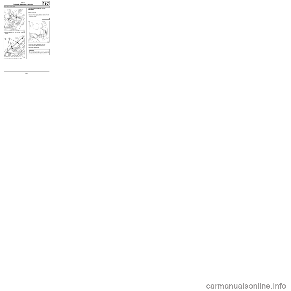
aRemove the bolts (12) from the rear brake hose
mounting.
aDetach the brake pipes from the body (13) .II - OPERATION FOR REMOVAL OF PART
CONCERNED
aRemove the fuel vapour absorber (see 14A, Anti-
pollution, Fuel vapour absorber: Removal - Refit-
ting, page 14A-4) .
aDisconnect the anti-splashback pipe (14) .
aRemove the clip (15) from the filling pipe.
aDisconnect the filling pipe.
119686
119688
D4F or D7F or K4M
121722
WARNING
To prevent impur ities from entering the circuit,
plugs must be fitted to the openings of all the fuel
circuit components exposed to the open air.
Page 623 of 652
19C-9
TANK
Fuel tank: Removal - Refitting
D4F or D7F or K4M or K9K
19C
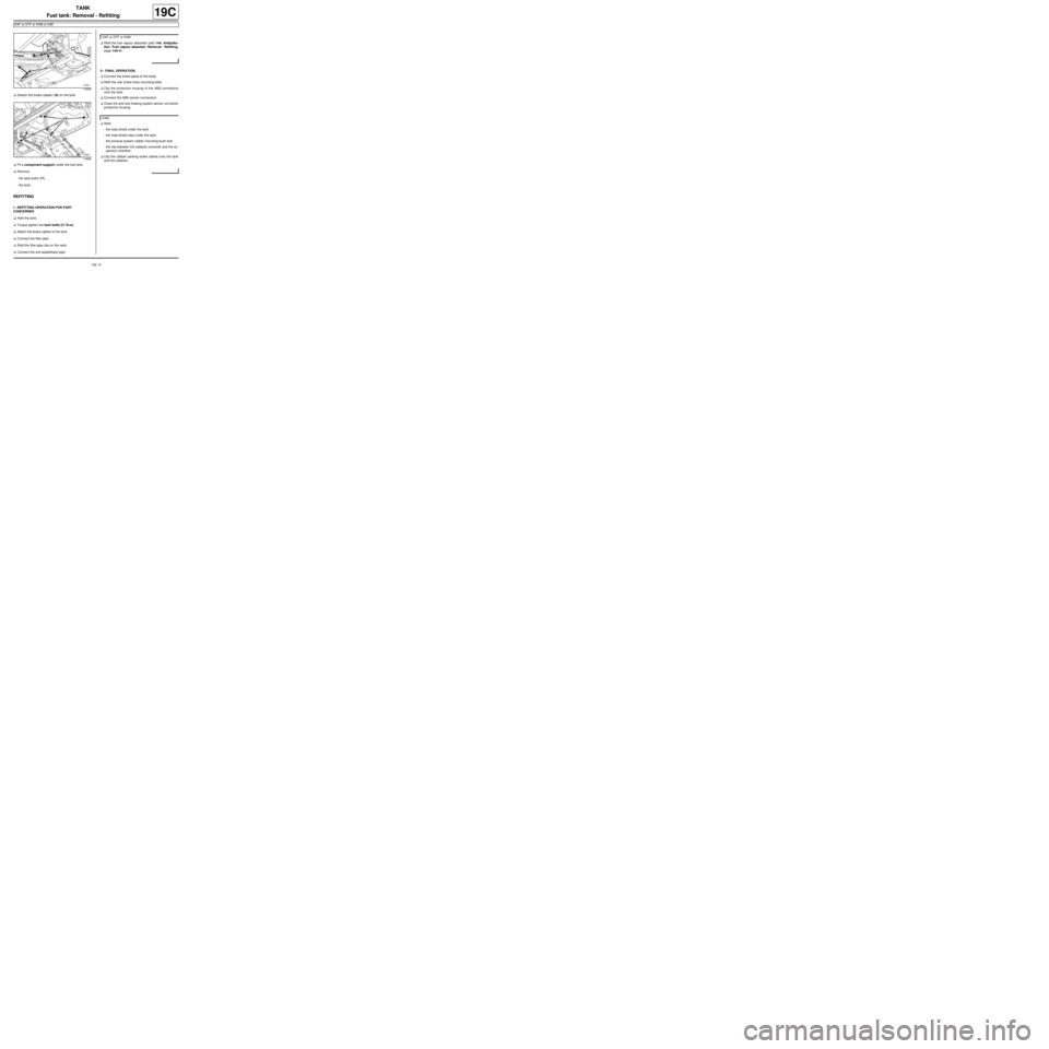
aDetach the brake cables (16) on the tank.
aFit a component support under the fuel tank.
aRemove:
-the tank bolts (17) ,
-the tank.
REFITTING
I - REFITTING OPERATION FOR PART
CONCERNED
aRefit the tank.
aTorque tighten the tank bolts (21 N.m).
aAttach the brake cables to the tank.
aConnect the filler pipe.
aRefit the filler pipe clip on the neck.
aConnect the anti-splashback pipe.aRefit the fuel vapour absorber (see 14A, Antipollu-
tion, Fuel vapour absorber: Removal - Refitting,
page 14A-4) .
II - FINAL OPERATION.
aConnect the brake pipes to the body.
aRefit the rear brake hose mounting bolts.
aClip the protective housing of the ABS connectors
onto the tank.
aConnect the ABS sensor connectors.
aClose the anti-lock braking system sensor connector
protective housing.
aRefit:
-the heat shield under the tank.
-the heat shield clips under the tank,
-the exhaust system rubber mounting bush bolt,
-the clip between the catalytic converter and the ex-
pansion chamber,
aClip the calliper parking brake cables onto the tank
and the callipers.
119652
119685
D4F or D7F or K4M
K4M