engine RENAULT TWINGO RS 2009 2.G Engine And Peripherals Workshop Manual
[x] Cancel search | Manufacturer: RENAULT, Model Year: 2009, Model line: TWINGO RS, Model: RENAULT TWINGO RS 2009 2.GPages: 652
Page 419 of 652
14A-1
ANTIPOLLUTION
Oil vapour rebreathing circuit: Descriptions
K9K
14A
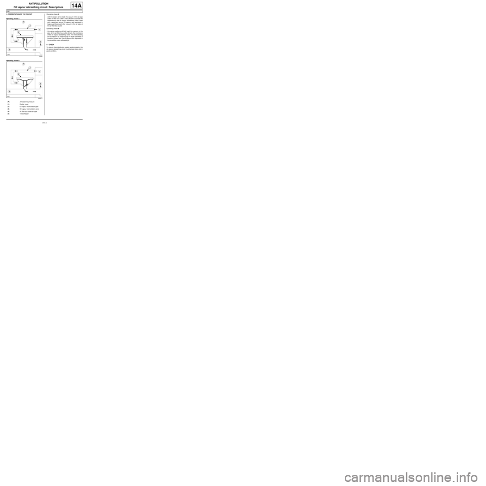
I - PRESENTATION OF THE CIRCUIT
Operating phase A
Operating phase BOperating phase A :
-with the engine at low load, the vacuum in the air pipe
at the air filter box outlet is not sufficient to activate the
membrane of the oil vapour rebreathing valve, fitted
with a weighted spring. Oil vapours are aspirated in
large quantities due to the vacuum in the air pipe at
the air filter box outlet.
Operating phase B :
-At engine medium and high load, the vacuum in the
pipe at the air filter box outlet attracts the membrane
of the oil vapour rebreathing valve. The hole allowing
the oil vapours to pass through in large quantities is
therefore closed and the oil vapours are aspirated in
low quantities via a calibrated jet.
II - CHECK
To ensure the antipollution system works properly, the
oil vapour rebreathing circuit must be kept clean and in
good condition.
20965
20965-1
(P) Atmospher ic pressure
(1) Rocker cover
(2) Oil vapour recirculation pipe
(3) Oil vapour recirculation valve
(4) Air filter box outlet air pipe
(5) Turbocharger
Page 421 of 652
14A-3
ANTIPOLLUTION
Fuel vapour recirculation circuit: Check
D4F or D7F
14A
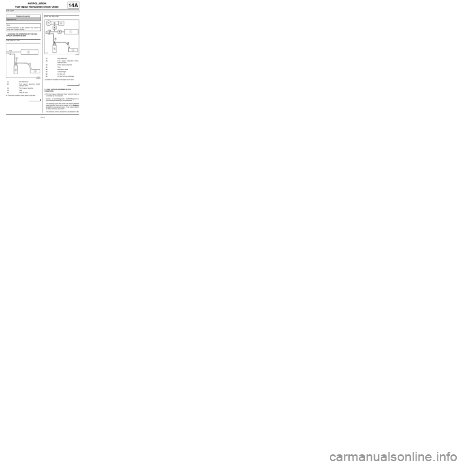
I - CHECKING THE OPERATION OF THE FUEL
VAPOUR ABSORBER BLEED
aCheck the condition of the pipes to the tank.aCheck the condition of the pipes to the tank.
II - FUEL VAPOUR ABSORBER BLEED
CONDITIONS
aThe fuel vapour absorber bleed solenoid valve is
controlled by the computer.
During « on board diagnostic » fault finding, fuel va-
pour absorber bleeding is not authorised.
The opening cyclic ratio of the fuel vapour absorber
bleed solenoid valve can be viewed on the Diagnos-
tic tool by reading parameter « Fuel vapour absorb-
er bleed solenoid valve OCR » .
The solenoid valve is closed for a value below 1.2%. Equipment required
Diagnostic tool
Note:
Incorrect operation of the system may result in
rough idle or engine stalling.
D4F, and 772 – D7F
97393-1
(1) Inlet distributor
(2) Fuel vapour absorber bleed
solenoid valve
(3) Petrol vapour absorber
(4) Tank
(5) Fresh air vent
D4F, and 780 or 782
121923
(1) Inlet distributor
(2) Fuel vapour absorber bleed
solenoid valve
(3) Petrol vapour absorber
(4) Tank
(6) Anti-retur n valve
(7) Turbocharger
(8) Air filter unit
(9) Air filter box air outlet pipe
Page 425 of 652
14A-7
ANTIPOLLUTION
Fuel vapour absorber: Check
D4F or D7F
14A
I - CHECKING THE FUEL VAPOUR ABSORBER
aOn the fuel vapour absorber, plug the circuit coming
from the fuel tank.
aConnect the pressure gauge of the (Mot. 1311-01)
to the fuel vapour absorber breather outlet.
aWith the engine at idle speed, check that no vacuum
is present at the fuel vapour absorber breather out-
let. In the same way, the control value read by the
Diagnostic tool in parameter « fuel vapour absorb-
er bleed solenoid valve OCR » remains minimal X
less than or equal to 1.5%.
Is there a vacuum?
-Yes: With the ignition off, use a manual vacuum
and pressure pump to apply a vacuum of 500
mbar to the solenoid valve outlet. The vacuum
pressure should not vary by more than 10 mbar
over 30 seconds.
•Does the pressure vary?
-Yes: the solenoid valve is faulty, replace it (see
17B, Petrol injection, Petrol injection: List
and location of components, page 17B-1) .
-No: if it is an electrical problem, check the circuit
(see MR 413 Fault finding, 17B, Petrol injec-
tion, Fault finding - Interpretation of faults,
Canister bleed solenoid valve circuit).
-No: In bleeding condition (see « bleeding
condition » ), the vacuum should increase. In the
same time, the value of the parameter on the Diag-
nostic tool increases.
II - CHECKING THE FUEL VAPOUR ABSORBER-
TANK CONNECTION
aCheck this connection by connecting a manual vac-
uum and pressure pump to the pipe leading to the
fuel vapour absorber.Special tooling required
Mot. 1311-01Pressure gauges and petrol
pressure measur ing unions.
Equipment required
Diagnostic tool
man ual vacuum and pressure pump
Page 428 of 652
14A-10
ANTIPOLLUTION
Exhaust gas recirculation solenoid valve: Removal - Refitting
K9K
14A
PARTS AND CONSUMABLES FOR THE
REPAIR WORK
aConsumables (see Vehicle: Parts and consuma-
bles for the repair) (02A, Parts and consumables):
-ABRASIVE PAD,
-SURFACE CLEANER.
REMOVAL
I - REMOVAL PREPARATION OPERATION
aRemove:
-the engine cover,
-the air filter box (see 12A, Fuel mixture, Air filter
unit: Removal - Refitting, page 12A-13) .
II - OPERATION FOR REMOVAL OF PART
CONCERNED
aRemove:
-the bolts (1) from the exhaust gas recirculation so-
lenoid valve,
-the exhaust gas recirculation solenoid valve,
-the exhaust gas recirculation solenoid valve seal.
REFITTING
I - REFITTING PREPARATIONS OPERATION
aUsing the ABRASIVE PADS, clean the joint faces of
the exhaust gas recirculation solenoid valve.
aAfterwards, degrease these bearing faces using
SURFACE CLEANER and clean cloths.
aRefit a new seal on the exhaust gas recirculation so-
lenoid valve.
II - REFITTING OPERATION FOR PART
CONCERNED
aRefit:
-the exhaust gas recirculation solenoid valve with its
new seal,
-the bolts to the exhaust gas recirculation solenoid
valve.
aTorque tighten the exhaust gas recirculation sole-
noid valve bolts (10 Nm).
III - FINAL OPERATION.
aRefit:
-the air filter box (see 12A, Fuel mixture, Air filter
unit: Removal - Refitting, page 12A-13) ,
-the engine cover.
aIf the EGR solenoid valve is being replaced, carry
out the necessary programming (see MR 413 Fault
finding, 13B, Fault finding - Replacement of com-
ponents, Operation for replacing the EGR sole-
noid valve). Tightening torquesm
exhaust gas recircula-
tion solenoid valve bolts10 Nm
121637
Page 429 of 652
14A-11
ANTIPOLLUTION
Exhaust gas cooler: Removal - Refitting
K9K
14A
REMOVAL
I - REMOVAL PREPARATION OPERATION
aPosition the vehicle on a two-post lift (see Vehicle:
Towing and lifting) (02A, Lifting equipment).
aDisconnect the battery (see ) (80A, Battery).
aRemove:
-the engine cover,
-the windscreen wiper arms (see Windscreen wip-
er arm: Removal - Refitting) (85A, Wiping -
Washing),
-the scuttle panel grille (see Scuttle panel grille:
Removal - Refitting) (56A, Exterior equipment),
-the scoop under the scuttle panel grille (see Scoop
under the scuttle panel grille: Removal - Refit-
ting) (56A, Exterior equipment),
-the air filter unit (see 12A, Fuel mixture, Air filter
unit: Removal - Refitting, page 12A-13) ,
-the EGR solenoid valve (see 14A, Antipollution,
Exhaust gas recirculation solenoid valve: Re-
moval - Refitting, page 14A-10) ,
-the lower engine tie-bar (see 19D, Engine mount-
ing, Lower engine tie-bar: Removal - Refitting,
page 19D-18) ,
-the catalytic converter (see 19B, Exhaust, Cata-
lytic converter: Removal - Refitting, page 19B-
12) ,-the exhaust gas recirculation rigid pipe (see 14A,
Antipollution, Exhaust gas recirculation rigid
pipe: Removal - Refitting, page 14A-19) ,
-the exhaust gas recirculation assembly (see 14A,
Antipollution, Exhaust gas recirculation as-
sembly: Removal - Refitting, page 14A-15) .
II - OPERATION FOR REMOVAL OF PART
CONCERNED
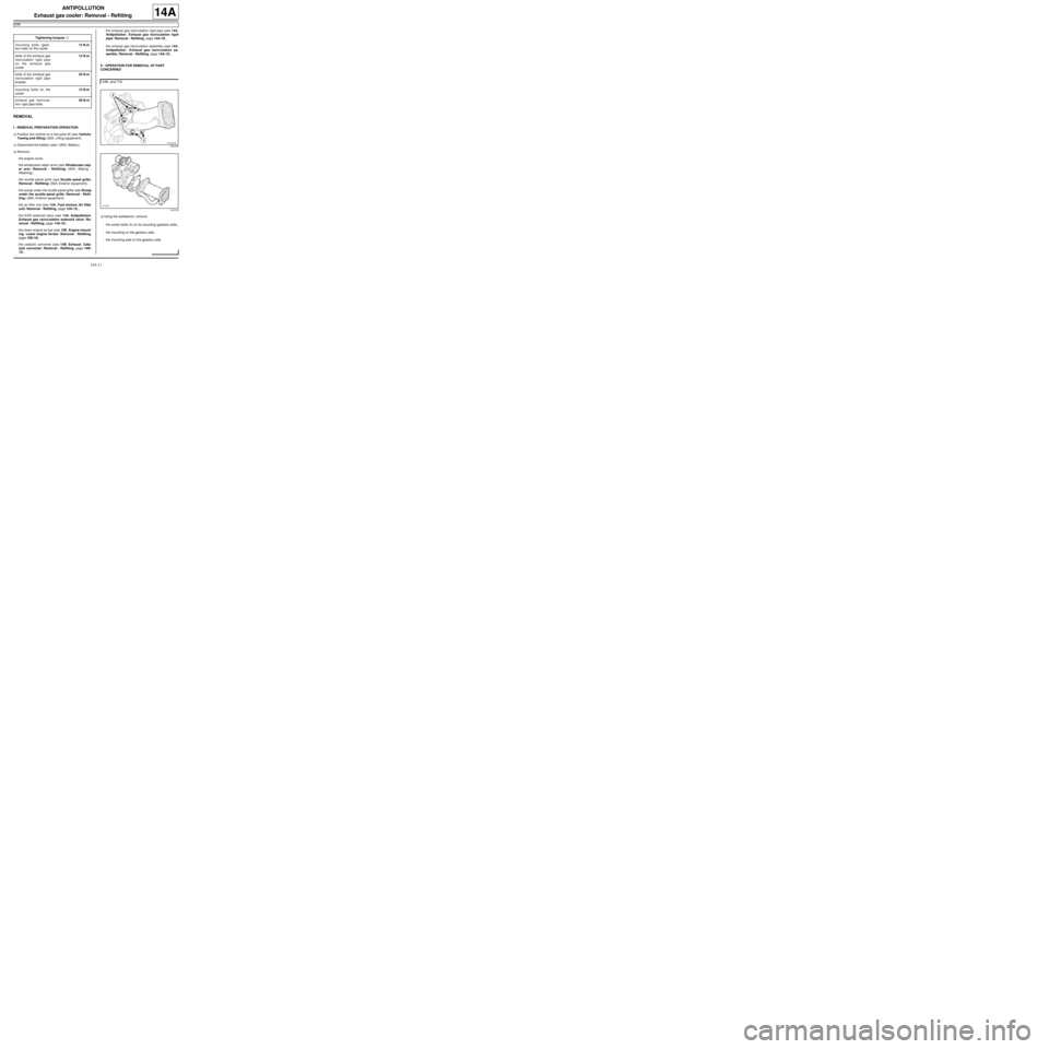
aUsing the workbench, remove:
-the cooler bolts (1) on its mounting (gearbox side),
-the mounting on the gearbox side,
-the mounting seal on the gearbox side. Tightening torquesm
mounting bolts (gear-
box side) on the cooler12 N.m
bolts of the exhaust gas
recirculation rigid pipe
on the exhaust gas
cooler12 N.m
bolts of the exhaust gas
recirculation rigid pipe
bracket25 N.m
mounting bolts on the
cooler12 N.m
exhaust gas recircula-
tion r igid pipe bolts36 N.m
K9K, and 718
141215
141216
Page 432 of 652
14A-14
ANTIPOLLUTION
Exhaust gas cooler: Removal - Refitting
K9K
14A
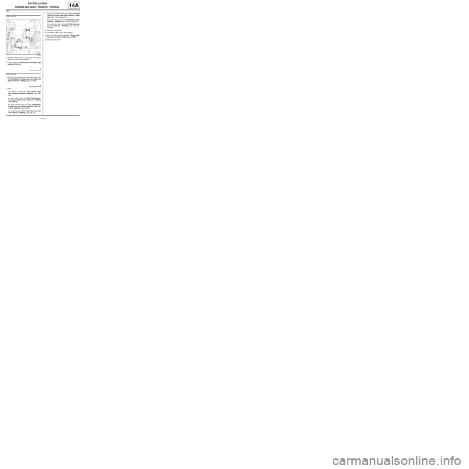
aRefit the bolts (4) of the exhaust gas recirculation
rigid pipe on the exhaust manifold.
aTorque tighten the exhaust gas recirculation rigid
pipe bolts (36 N.m).
aRefit the rigid exhaust gas recirculation pipe (see
14A, Antipollution, Exhaust gas recirculation rig-
id pipe: Removal - Refitting, page 14A-19) .
aRefit:
-the catalytic converter (see 19B, Exhaust, Cata-
lytic converter: Removal - Refitting, page 19B-
12) ,
-the lower engine tie-bar (see 19D, Engine mount-
ing, Lower engine tie-bar: Removal - Refitting,
page 19D-18) ,
-the EGR solenoid valve (see 14A, Antipollution,
Exhaust gas recirculation solenoid valve: Re-
moval - Refitting, page 14A-10) ,
-the air filter unit (see 12A, Fuel mixture, Air filter
unit: Removal - Refitting, page 12A-13) ,-the scoop under the scuttle panel grille (see Scoop
under the scuttle panel grille: Removal - Refit-
ting) (56A, Exterior equipment),
-the scuttle panel grille (see Scuttle panel grille:
Removal - Refitting) (56A, Exterior equipment),
-the windscreen wiper arms (see Windscreen wip-
er arm: Removal - Refitting) (85A, Wiping -
Washing),
aTop up the coolant level.
aConnect the battery (see ) (80A, Battery).
aBleed the cooling system (see 19A, Cooling, Cool-
ing system: Draining - Refilling, page 19A-9) .
aRefit the engine cover. K9K, and 718
141224
K9K, and 740
Page 433 of 652
14A-15
ANTIPOLLUTION
Exhaust gas recirculation assembly: Removal - Refitting
K9K
14A
REMOVAL
I - REMOVAL PREPARATION OPERATION
aPosition the vehicle on a two-post lift (see Vehicle:
Towing and lifting) (02A, Lifting equipment).
aDisconnect the battery (see ) (80A, Battery).
aRemove:
-the engine cover,
-the windscreen wiper arms (see Windscreen wip-
er arm: Removal - Refitting) (85A, Wiping -
Washing)
-the scuttle panel grille (see Scuttle panel grille:
Removal - Refitting) (56A, Exterior equipment),
-the scoop under the scuttle panel grille (see Scoop
under the scuttle panel grille: Removal - Refit-
ting) (56A, Exterior equipment),
-the air filter unit (see 12A, Fuel mixture, Air filter
unit: Removal - Refitting, page 12A-13) ,
-the EGR solenoid valve (see 14A, Antipollution,
Exhaust gas recirculation solenoid valve: Re-
moval - Refitting, page 14A-10) ,
-the lower engine tie-bar (see 19D, Engine mount-
ing, Lower engine tie-bar: Removal - Refitting,
page 19D-18) ,
-the catalytic converter (see 19B, Exhaust, Cata-
lytic converter: Removal - Refitting, page 19B-
12) ,
-the rigid exhaust gas recirculation pipe (see 14A,
Antipollution, Exhaust gas recirculation rigid
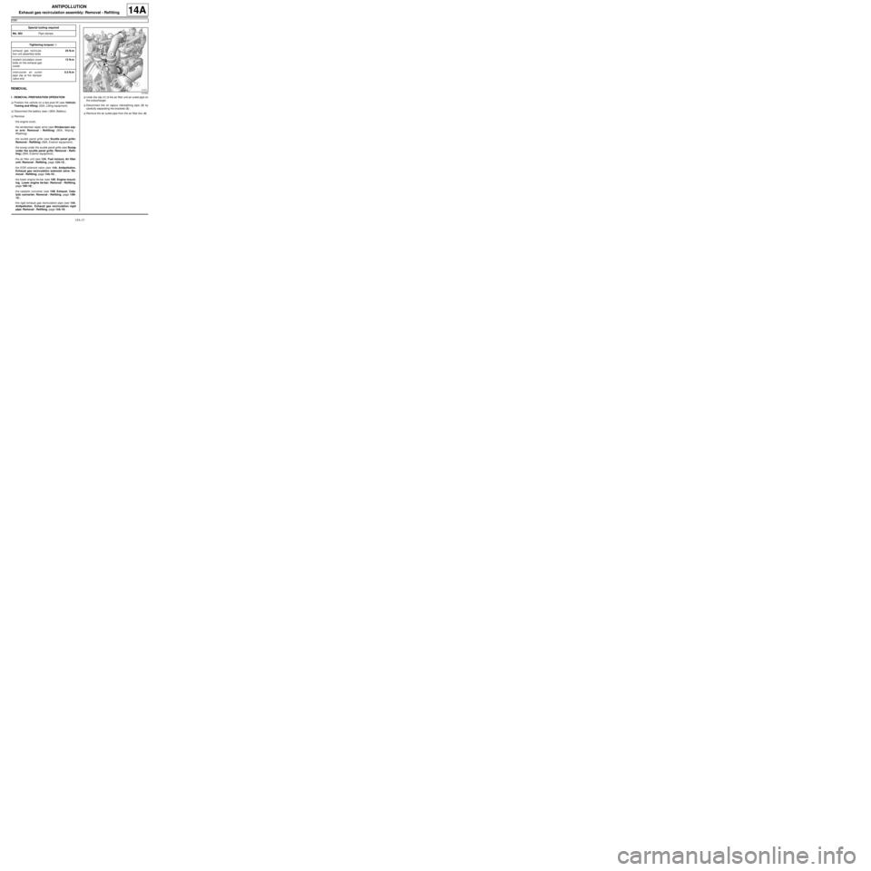
pipe: Removal - Refitting, page 14A-19) .aUndo the clip (1) of the air filter unit air outlet pipe on
the turbocharger.
aDisconnect the oil vapour rebreathing pipe (2) by
carefully separating the brackets (3) .
aRemove the air outlet pipe from the air filter box (4) . Special tooling required
Ms. 583Pipe clamps .
Tightening torquesm
exhaust gas recircula-
tion unit assembly bolts25 N.m
coolant circulation cover
bolts on the exhaust gas
cooler12 N.m
intercooler air outlet
pipe clip at the damper
valve end5.5 N.m
121633
Page 436 of 652
14A-18
ANTIPOLLUTION
Exhaust gas recirculation assembly: Removal - Refitting
K9K
14A
aRefit:
-new seals on the coolant circulation cover,
-the coolant circulation cover on the exhaust gas
cooler.
aTorque tighten the coolant circulation cover bolts
on the exhaust gas cooler (12 N.m).
aRemove the tool (Ms. 583) from the coolant inlet and
outlet hoses of the exhaust gas cooler.
III - FINAL OPERATION
aFit the intercooler air outlet pipe at the damper valve
end.
aConnect the intercooler air outlet pipe on the side of
the damper valve.
aTorque tighten the intercooler air outlet pipe clip
at the damper valve end (5.5 N.m).
aRefit the intercooler air outlet pipe nut on the lifting
eye.
aConnect the turbocharging pressure regulator vacu-
um pipe.
aClip:
-the turbocharging pressure regulator vacuum pipe,
-the vacuum pipe from the brake servo.
aConnect the brake servo vacuum pipe.
aFit the intercooler air inlet pipe at the turbocharger
end.
aRefit the intercooler air inlet pipe nut at the turbo-
charger end on the lifting eye.
aConnect the intercooler air inlet pipe at the turbo-
charger end.
aClip on the intercooler air inlet pipe clip at the turbo-
charger end.
aRefit the air outlet pipe onto the air filter unit.
aTighten the air filter unit air outlet pipe clip on the tur-
bocharger.
aConnect the oil vapour rebreathing pipe.
aRefit:
-the exhaust gas recirculation rigid pipe (see 14A,
Antipollution, Exhaust gas recirculation rigid
pipe: Removal - Refitting, page 14A-19) ,-the catalytic converter (see 19B, Exhaust, Cata-
lytic converter: Removal - Refitting, page 19B-
12) ,
-the lower engine tie-bar (see 19D, Engine mount-
ing, Lower engine tie-bar: Removal - Refitting,
page 19D-18) ,
-the EGR solenoid valve (see 14A, Antipollution,
Exhaust gas recirculation solenoid valve: Re-
moval - Refitting, page 14A-10) ,
-the air filter unit (see 12A, Fuel mixture, Air filter
unit: Removal - Refitting, page 12A-13) ,
-the scoop under the scuttle panel grille (see Scoop
under the scuttle panel grille: Removal - Refit-
ting) (56A, Exterior equipment).
-the scuttle panel grille (see Scuttle panel grille:
Removal - Refitting) (56A, Exterior equipment),
-the windscreen wiper arms (see Windscreen wip-
er arm: Removal - Refitting) (85A, Wiping -
Washing),
aConnect the battery (see ) (80A, Battery).
aFill and bleed the cooling system (see 19A, Cool-
ing, Cooling system: Draining - Refilling, page
19A-9) .
aRefit the engine cover. K9K, and 718
Page 437 of 652
14A-19
ANTIPOLLUTION
Exhaust gas recirculation rigid pipe: Removal - Refitting
K9K
14A
REMOVAL
I - REMOVAL PREPARATION OPERATION
aPosition the vehicle on a two-post lift (see Vehicle:
Towing and lifting) (02A, Lifting equipment).
aDisconnect the battery (see ) (80A, Battery).
aRemove:
-the engine cover,
-the windscreen wiper arms (see Windscreen wip-
er arm: Removal - Refitting) (85A, Wiping -
Washing),
-the scuttle panel grille (see Scuttle panel grille:
Removal - Refitting) (56A, Exterior equipment),
-the scoop under the scuttle panel grille (see Scoop
under the scuttle panel grille: Removal - Refit-
ting) (56A, Exterior equipment),
-the air filter unit (see 12A, Fuel mixture, Air filter
unit: Removal - Refitting, page 12A-13) ,
-the lower engine tie-bar (see 19D, Engine mount-
ing, Lower engine tie-bar: Removal - Refitting,
page 19D-18) ,
-the catalytic converter (see 19B, Exhaust, Cata-
lytic converter: Removal - Refitting, page 19B-
12) .II - OPERATION FOR REMOVAL OF PART
CONCERNED
aRemove:
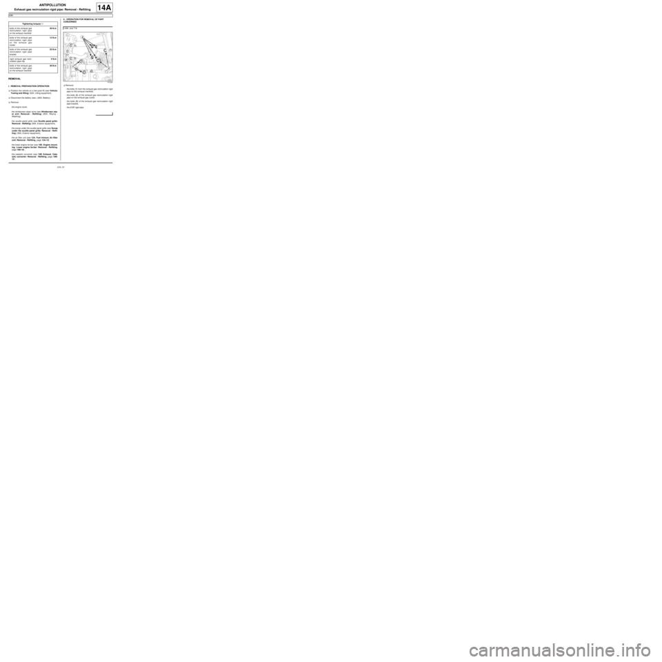
-the bolts (1) from the exhaust gas recirculation rigid
pipe on the exhaust manifold,
-the bolts (2) of the exhaust gas recirculation rigid
pipe on the exhaust gas cooler,
-the bolts (3) of the exhaust gas recirculation rigid
pipe bracket,
-the EGR rigid pipe. Tightening torquesm
bolts of the exhaust gas
recirculation rigid pipe
on the exhaust manifold36 N.m
bolts of the exhaust gas
recirculation rigid pipe
on the exhaust gas
cooler12 N.m
bolts of the exhaust gas
recirculation rigid pipe
bracket25 N.m
rigid exhaust gas recir-
culation pipe clip5 N.m
bolts of the exhaust gas
recirculation rigid pipe
on the exhaust manifold36 N.m
K9K, and 718
141224
Page 439 of 652
14A-21
ANTIPOLLUTION
Exhaust gas recirculation rigid pipe: Removal - Refitting
K9K
14A
aRefit the exhaust gas recirculation rigid pipe with a
new clip.
aFit the rigid exhaust gas recirculation pipe bolts,
without tightening them.
aAdjust the rigid exhaust gas recirculation pipe in re-
lation to the exhaust gas recirculation assembly.
aTorque tighten the rigid exhaust gas recirculation
pipe clip (5 N.m).
aCheck that the rigid exhaust gas recirculation pipe is
not constrained.
aTorque tighten the bolts of the exhaust gas recir-
culation rigid pipe on the exhaust manifold (36
N.m).
III - FINAL OPERATION
aRefit:
-the catalytic converter (see 19B, Exhaust, Cata-
lytic converter: Removal - Refitting, page 19B-
12) ,
-the lower engine tie-bar (see 19D, Engine mount-
ing, Lower engine tie-bar: Removal - Refitting,
page 19D-18) ,
-the air filter unit (see 12A, Fuel mixture, Air filter
unit: Removal - Refitting, page 12A-13) ,
-the scoop under the scuttle panel grille (see Scoop
under the scuttle panel grille: Removal - Refit-
ting) (56A, Exterior equipment),
-the scuttle panel grille (see Scuttle panel grille:
Removal - Refitting) (56A, Exterior equipment),
-the windscreen wiper arms (see Windscreen wip-
er arm: Removal - Refitting) (85A, Wiping -
Washing),
-the engine cover.
aConnect the battery (see ) (80A, Battery). K9K, and 740