engine RENAULT TWINGO RS 2009 2.G Engine And Peripherals Workshop Manual
[x] Cancel search | Manufacturer: RENAULT, Model Year: 2009, Model line: TWINGO RS, Model: RENAULT TWINGO RS 2009 2.GPages: 652
Page 453 of 652
16A-14
STARTING - CHARGING
Starter: Removal - Refitting
K9K
16A
REMOVAL
I - REMOVAL PREPARATION OPERATION
aDisconnect the battery (see ) (MR 411, 80A, Bat-
tery).
aRemove the front engine cover.
II - OPERATION FOR REMOVAL OF PART
CONCERNED
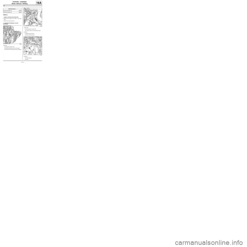
aRemove:
-the electrical connection nuts,
-the electrical connections (1) from the starter,
-the wiring channel mounting clip from the gearbox.aDisconnect:
-the accelerometer connector (2) ,
-the connector (3) from the rail pressure sensor.
aRemove:
-the gearbox wiring channel,
-the starter electrical harness.
aRemove:
-the starter bolts (4) ,
-the starter. Tightening torquesm
electr ical connection nut5 N.m
electr ical connection nut8 N.m
121432
121420
121417
Page 454 of 652

16A-15
STARTING - CHARGING
Starter: Removal - Refitting
K9K
16A
REFITTING
I - REFITTING OPERATION FOR PART
CONCERNED
aRefit:
-the starter,
-the starter bolts.
aTighten the starter bolts.
aFit:
-the starter wiring harness,
-the gearbox wiring channel.
aRefit:
-the wiring channel mounting clip on the gearbox,
-the electrical connections on the starter,
-the electrical connection nuts.
aTighten to torque:
-the electrical connection nut (5 N.m) (5) ,
-the electrical connection nut (8 N.m) (6) .
aConnect:
-the accelerometer connector,
-the rail pressure sensor connector.
II - FINAL OPERATION
aRefit the engine cover.
aConnect the battery (see ) (MR 411, 80A, Battery).
121432
Page 476 of 652
17B-1
PETROL INJECTION
Petrol injection: List and location of components
D4F, and 772
17B
121740
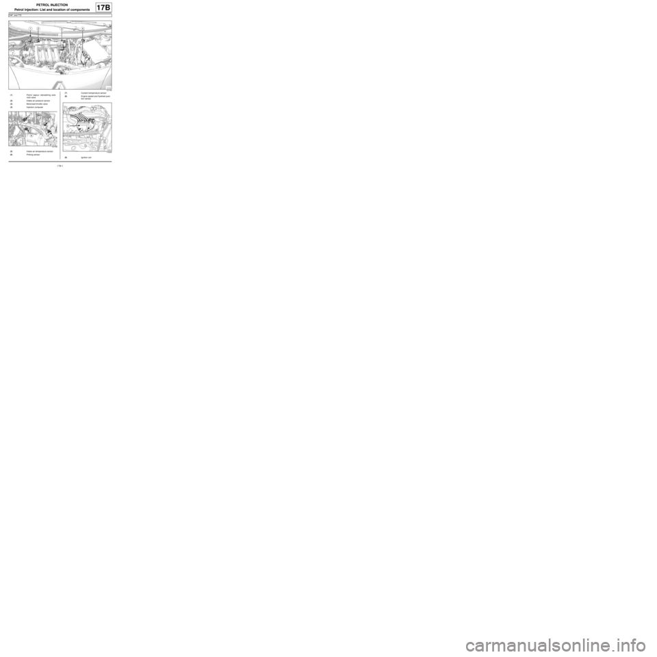
(1) Petrol vapour rebreathing sole-
noid valve
(2) Intake air pressure sensor
(3) Motorised throttle valve
(4) Injection computer
121739
(5) Intake air temperature sensor
(6) Pinking sensor
(7) Coolant temper ature sensor
(8) Engine speed and flywheel posi-
tion sensor
113044
(9) Ignition coil
Page 479 of 652
17B-4
PETROL INJECTION
Petrol injection: List and location of components
D7F, and 800
17B
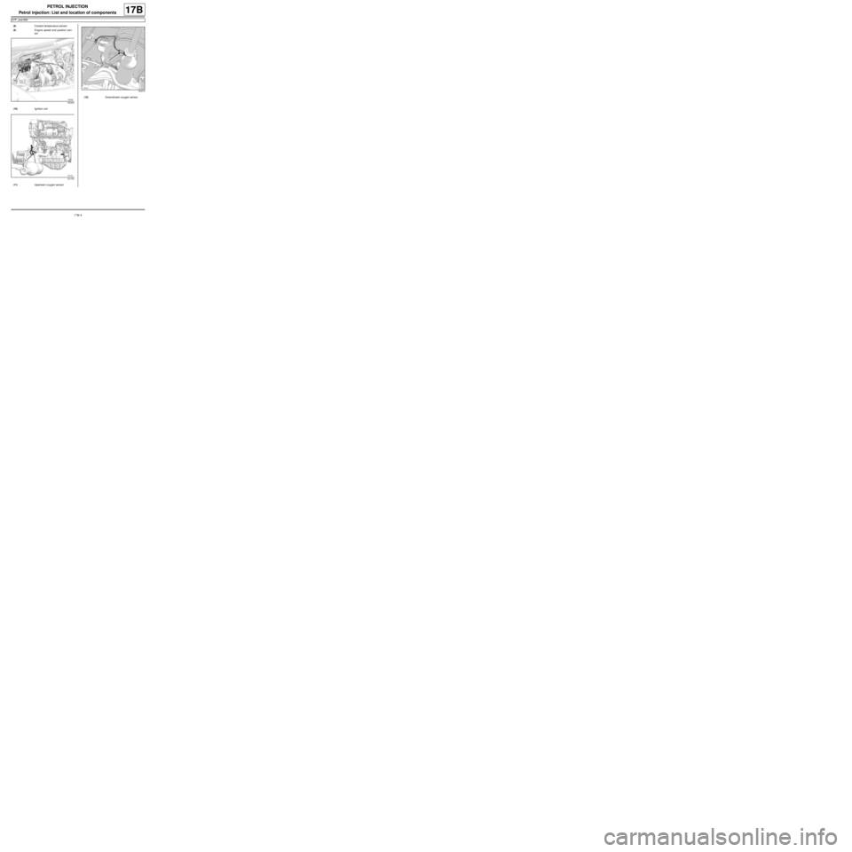
(8) Coolant temper ature sensor
(9) Engine speed and position sen-
sor
120404
(10) Ignition coil
121732
(11) Upstream oxygen sensor
120415
(12) Downstream oxygen sensor
Page 480 of 652
17B-5
PETROL INJECTION
Petrol injection: List and location of components
D4F, and 780 or 782
17B
122387
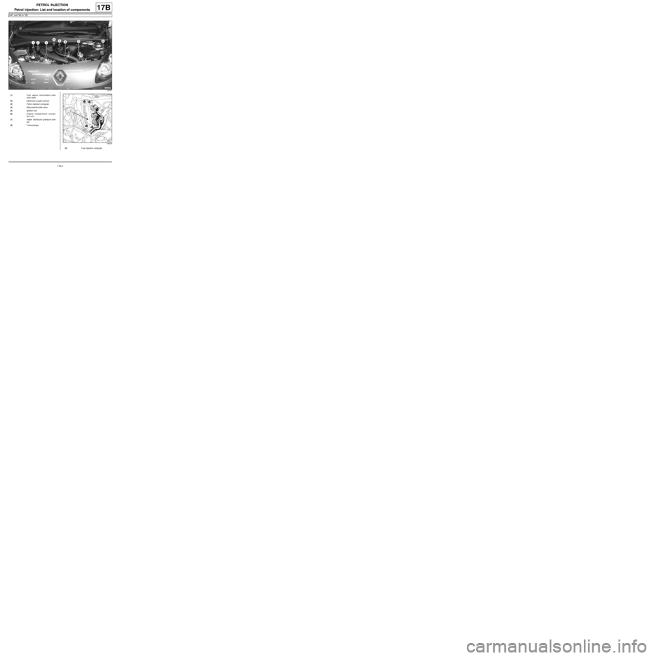
(1) Fuel vapour recirculation sole-
noid valve
(2) Upstream oxygen sensor
(3) Petrol injection computer
(4) Motorised throttle valve
(5) Ignition coil
(6) Engine compar tment connec-
tion unit
(7) Intake distributor pressure sen-
sor
(8) Turbocharger
108254
(9) Fuel injection computer
Page 492 of 652
17B-17
PETROL INJECTION
Oxygen sensors: Removal - Refitting
K4M
17B
REMOVING THE UPSTREAM OXYGEN
SENSOR
I - REMOVAL PREPARATION OPERATION
aPosition the vehicle on a two-post lift (see Vehicle:
Towing and lifting) (02A, Lifting equipment).
aRemove:
-the front right-hand wheel (see Wheel: Removal -
Refitting) (35A, Wheels and tyres),-the front right-hand wheel arch liner (see Front
wheel arch liner: Removal - Refitting) (55A, Ex-
terior protection),
-the engine undertray.
II - REMOVAL OPERATION
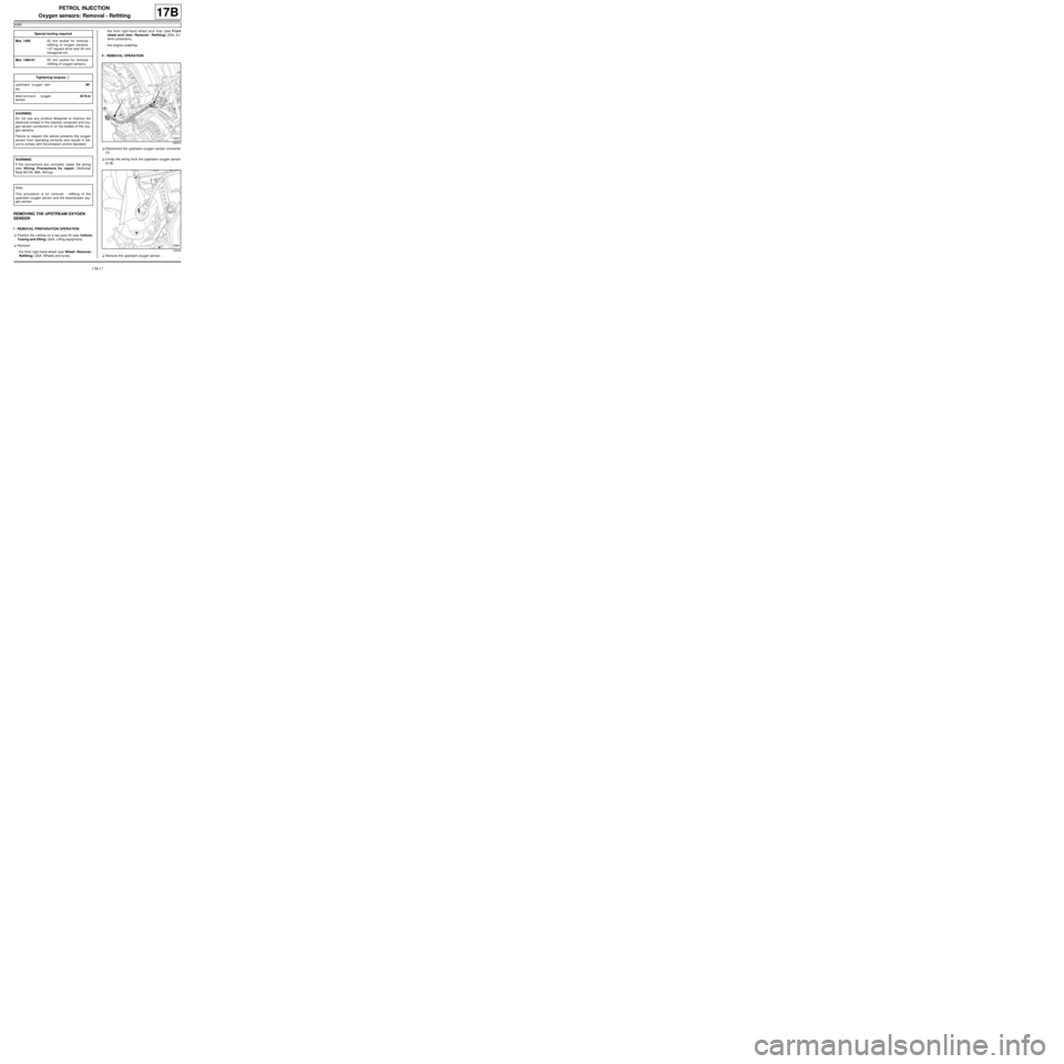
aDisconnect the upstream oxygen sensor connector
(1) .
aUnclip the wiring from the upstream oxygen sensor
at (2) .
aRemove the upstream oxygen sensor . Special tooling required
Mot. 149522 mm socket for removal -
refitting of oxygen sensors -
1/2" square dr ive and 24 mm
hexagonal ext.
Mot. 1495-0122 mm socket for removal -
refitting of oxygen sensors.
Tightening torquesm
upstream oxygen sen-
sor90˚
downstream oxygen
sensor45 N.m
WARNING
Do not use any product designed to improve the
electr ical contact in the injection computer and oxy-
gen sensor connectors or on the bodies of the oxy-
gen sensors.
Failure to respect this advice prevents the oxygen
sensor from operating correctly and results in fail-
ure to comply with the emission control standard.
WARNING
If the connections are corroded, repair the wiring
(see Wiring: Precautions for repair) (Technical
Note 6015A, 88A, Wiring).
Note:
This procedure is for removal - refitting of the
upstream oxygen sensor and the downstream oxy-
gen sensor.
132373
132539
Page 493 of 652
17B-18
PETROL INJECTION
Oxygen sensors: Removal - Refitting
K4M
17B
REFITTING THE UPSTREAM OXYGEN
SENSOR
I - REFITTING PREPARATION OPERATION
aClean the threading of the upstream oxygen sensor
using a WIRE BRUSH.
aUse SURFACE CLEANER (see Vehicle: Parts
and consumables for the repair) (04B, Consuma-
bles - Products) to clean and degrease:
-the thread hole of the upstream oxygen sensor on
the exhaust manifold,
-the threading of the upstream oxygen sensor if it is
to be reused.
II - REFITTING OPERATION
aRefit the upstream oxygen sensor.
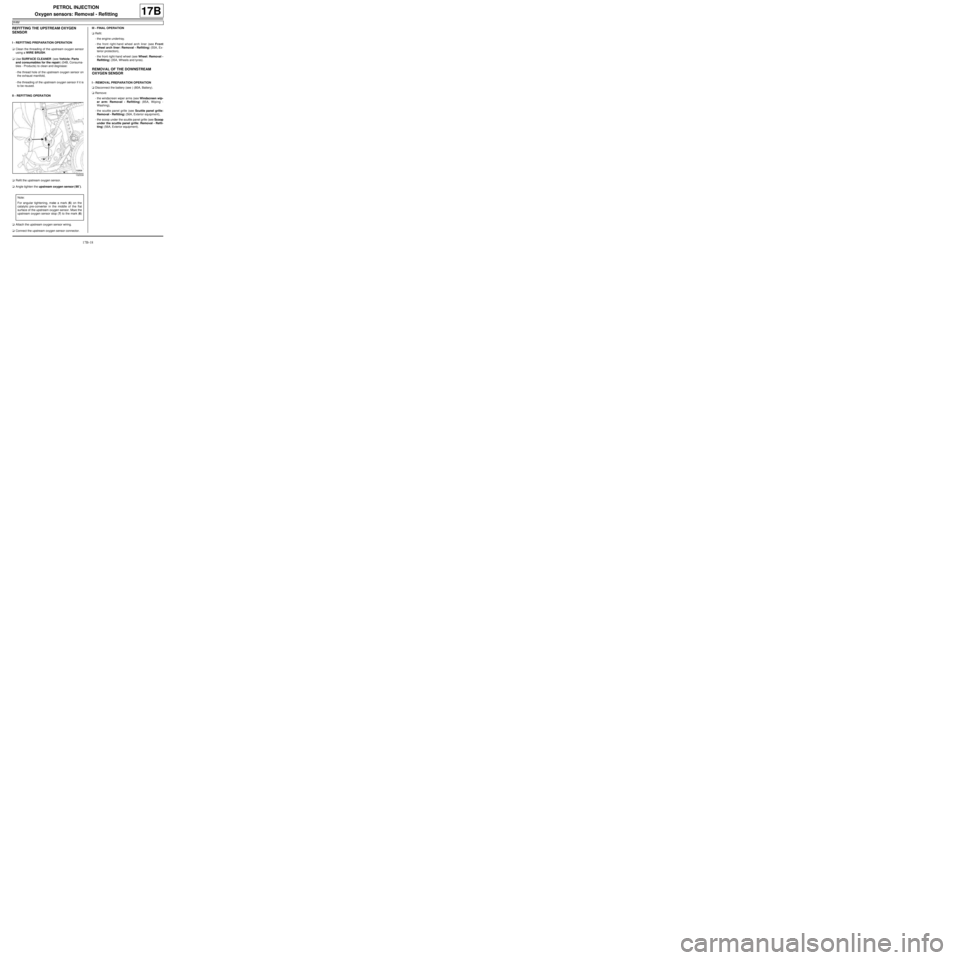
aAngle tighten the upstream oxygen sensor ( 90˚).
aAttach the upstream oxygen sensor wiring.
aConnect the upstream oxygen sensor connector.III - FINAL OPERATION
aRefit:
-the engine undertray.
-the front right-hand wheel arch liner (see Front
wheel arch liner: Removal - Refitting) (55A, Ex-
terior protection),
-the front right-hand wheel (see Wheel: Removal -
Refitting) (35A, Wheels and tyres).
REMOVAL OF THE DOWNSTREAM
OXYGEN SENSOR
I - REMOVAL PREPARATION OPERATION
aDisconnect the battery (see ) (80A, Battery).
aRemove:
-the windscreen wiper arms (see Windscreen wip-
er arm: Removal - Refitting) (85A, Wiping -
Washing),
-the scuttle panel grille (see Scuttle panel grille:
Removal - Refitting) (56A, Exterior equipment),
-the scoop under the scuttle panel grille (see Scoop
under the scuttle panel grille: Removal - Refit-
ting) (56A, Exterior equipment).
132539
Note:
For angular tightening, make a mark (6) on the
catalytic pre-converter in the middle of the flat
surface of the upstream oxygen sensor. Move the
upstream oxygen sensor stop (7) to the mark (6)
.
Page 500 of 652
17B-25
PETROL INJECTION
Crankshaft position sensor: Removal - Refitting
D4F or D7F
17B
REMOVAL
I - REMOVAL PREPARATION OPERATION
aRemove the air filter box (see 12A, Fuel mixture,
Air filter unit: Removal - Refitting, page 12A-13) .
aRemove the engine wiring bolt from the gearbox.
aMove the engine wiring harness to one side.
II - OPERATION FOR REMOVAL OF PART
CONCERNED
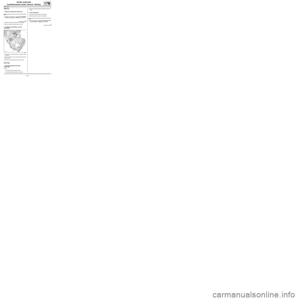
aDisconnect the engine speed and position sensor
connector.
aRemove the bolts (1) from the engine speed and po-
sition sensor.
aRemove the engine speed and position sensor.
REFITTING
I - REFITTING OPERATION FOR PART
CONCERNED
aRefit:
-the engine speed and position sensor,
-the engine speed and position sensor bolts.aConnect the engine speed and position sensor con-
nector.
II - FINAL OPERATION.
aConnect the engine wiring to the gearbox.
aRefit the engine wiring bolt to the gearbox.
aRefit the air filter box (see 12A, Fuel mixture, Air fil-
ter unit: Removal - Refitting, page 12A-13) . D4F
121409
D4F
Page 501 of 652
17B-26
PETROL INJECTION
Crankshaft position sensor: Removal - Refitting
K4M
17B
REMOVAL
I - REMOVAL PREPARATION OPERATION
aPosition the vehicle on a two-post lift (see Vehicle:
Towing and lifting) (02A, Lifting equipment).
aRemove the engine undertray.
II - REMOVAL OPERATION
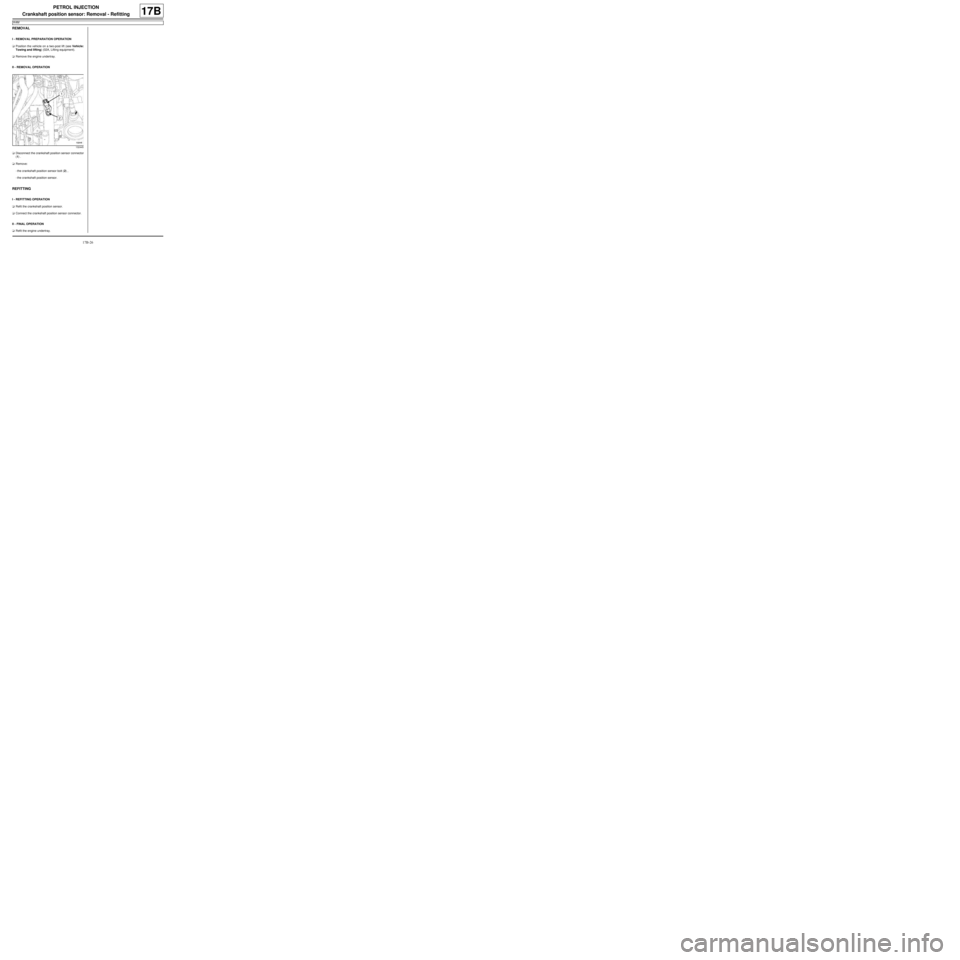
aDisconnect the crankshaft position sensor connector
(1) .
aRemove:
-the crankshaft position sensor bolt (2) ,
-the crankshaft position sensor.
REFITTING
I - REFITTING OPERATION
aRefit the crankshaft position sensor.
aConnect the crankshaft position sensor connector.
II - FINAL OPERATION
aRefit the engine undertray.
132445
Page 511 of 652
19A-1
COOLING
Engine cooling system: Specifications
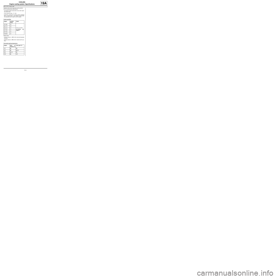
D4F or D7F or K4M or K9K
19A
Vehicles in the current range have cooling systems
with the following basic specifications:
-hermetically-sealed pressurised circuit (with expan-
sion bottle valve),
-circuit using only type « D » fluid,
-passenger compartment heating system equipped
with a « heater matrix » type radiator located under
the dashboard which helps to cool the engine.
Coolant quantities
Special notes:
-protection down to - 25˚C ±± ± ±
2 for cold and temperate
countries,
-protection down to - 40˚C ±± ± ±
2 for "extreme cold" coun-
tries.
Thermostat opening temperaturesEngine Quantity
(litres)Grade
D7F 800 5.5
Only use coolant
GLACEOL RX
(type D) D4F 772 5.5
K9K 740 5.7
D4F 780 5.7
D4F 782 5.7
K4M 854 5.7
Engine Star t o f
opening (˚C)Fully open (˚C)
D7F89 99
D4F89 99 ±± ± ±
2
K9K83 ±± ± ±
395
K4M89 101