engine RENAULT TWINGO RS 2009 2.G Engine And Peripherals Workshop Manual
[x] Cancel search | Manufacturer: RENAULT, Model Year: 2009, Model line: TWINGO RS, Model: RENAULT TWINGO RS 2009 2.GPages: 652
Page 404 of 652
13B-43
DIESEL INJECTION
Injector rail: Removal - Refitting
K9K
13B
REMOVAL
I - REMOVAL PREPARATION OPERATION
aPosition the vehicle on a two-post lift (see Vehicle:
Towing and lifting) (02A, Lifting equipment)
aRemove the front engine cover.
aDisconnect the battery (see Battery: Removal - Re-
fitting) (80A, Battery).
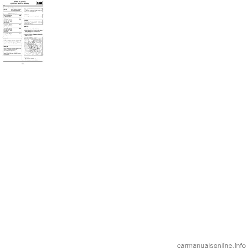
aDisconnect:
-the heater plug connectors (1) ,
-the connectors (2) from the injectors. Special tooling required
Mot. 1746Offset wrench for tightening
High Pressure pump pipes.
Tightening torquesm
studs of the injection rail
on the cylinder head8 Nm
injector rail nuts28 Nm
unions for the high pres-
sure pipes between the
rail and the yellow-
coloured injector24 Nm
unions for the high pres-
sure pipes between the
rail and the silver-
coloured injector28 Nm
unions for the high pres-
sure pipes between the
pump and the yellow-
coloured r ail24 Nm
unions for the high pres-
sure pipes between the
pump and the silver-
coloured r ail28 Nm
IMPORTANT
Consult the safety and cleanliness advice and oper-
ation recommendations before carrying out any
repair (see 13B, Diesel injection, Diesel injec-
tion: Precautions for the repair, page 13B-1) .
IMPORTANT
Use the diagnostic tool before any operation is car-
ried out on the injection circuit to check:
-that the rail is not under pressure,
-that the fuel temperature is not too high.
Working on the circuit with the engine running is
strictly forbidden.
WARNING
To avoid any corrosion or damage, protect the
areas on which fuel is likely to run.
IMPORTANT
Wear leaktight gloves (nitrile type) for this opera-
tion.
WARNING
To prevent impurities from entering the circuit, place
protective plugs on all fuel circuit components
exposed to the open air.
127895
Page 408 of 652
13B-47
DIESEL INJECTION
Injector rail: Removal - Refitting
K9K
13B
aRemove the blanking plugs.
aFit the injector rail.
aFit the injector rail nuts without tightening them.
III - FINAL OPERATION.
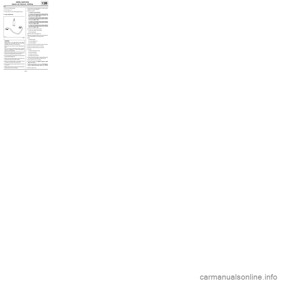
a
aRemove the blanking plugs from the high pressure
pump and the injection rail and discard them.
aFit the high pressure pipe between the high pressure
pump and the injection rail.
aTighten the high pressure pipe unions between the
pump and the rail until contact is made.
aRemove the blanking plugs on the injection rail and
the diesel fuel injectors then discard them.
aFit the new high-pressure pipes between the rail and
the injectors.
aTighten until contact the unions of the high pressure
pipes between the rail and injector.aFit and lock the new clips between the high pressure
pipes on the rail and injectors.
aTighten to torque:
-the injector rail nuts (28 Nm),
-the unions for the high pressure pipes between
the rail and the yellow-coloured injector (24
Nm) using the tool (Mot. 1746),
-the unions for the high pressure pipes between
the rail and the silver-coloured injector (28 Nm)
using the tool (Mot. 1746),
-the unions for the high pressure pipes between
the pump and the yellow-coloured rail (24 Nm)
using the tool (Mot. 1746),
-the unions for the high pressure pipes between
the pump and the silver-coloured rail (28 Nm)
using the tool (Mot. 1746),
aConnect to the high pressure pump:
-the fuel return pipe to the fuel filter,
-the fuel supply pipe.
aRefit the neck on the injection rail.
aRemove the protection fitted on the inlet opening of
the oil level dipstick on the cylinder block.
aRefit:
-the dipstick guide,
-the oil level dipstick nut,
-the oil level dipstick.
aConnect the injector rail pressure sensor connector.
aPosition the wiring harness in its channel.
aFasten the electrical wiring to the channel.
aConnect:
-the diesel temperature sensor,
-the fuel flow actuator,
-the injector connectors,
-the heater plug connectors.
aPrime the fuel circuit using a manual priming pump
until the disconnected pipes are filled with fuel.
aCheck that there are no fuel leaks.
aConnect the battery (see Battery: Removal - Refit-
ting) (80A, Battery).
aCheck the high pressure circuit (see 13B, Diesel in-
jection, High pressure pipe: Check, page 13B-34)
.
aRefit the engine cover.
20960
WARNING
Before fitting a new high-pressure pipe, lightly
lubricate the nut threads with the oil from the
applicator provided in the new parts kit.
Be careful not to allow oil into the high-pressure
pipe.
Do not lubricate high-pressure pipes supplied
without an applicator, as these high-pressure
pipes are self-lubricating.
Page 410 of 652
13B-49
DIESEL INJECTION
Fuel temperature sensor: Removal - Refitting
C44, and K9K
13B
REMOVAL
I - REMOVAL PREPARATION OPERATION
aRemove the front engine cover.
aDisconnect the battery ( (see Battery: Removal -
Refitting) ).
aProtect the alternator from fuel outflow.
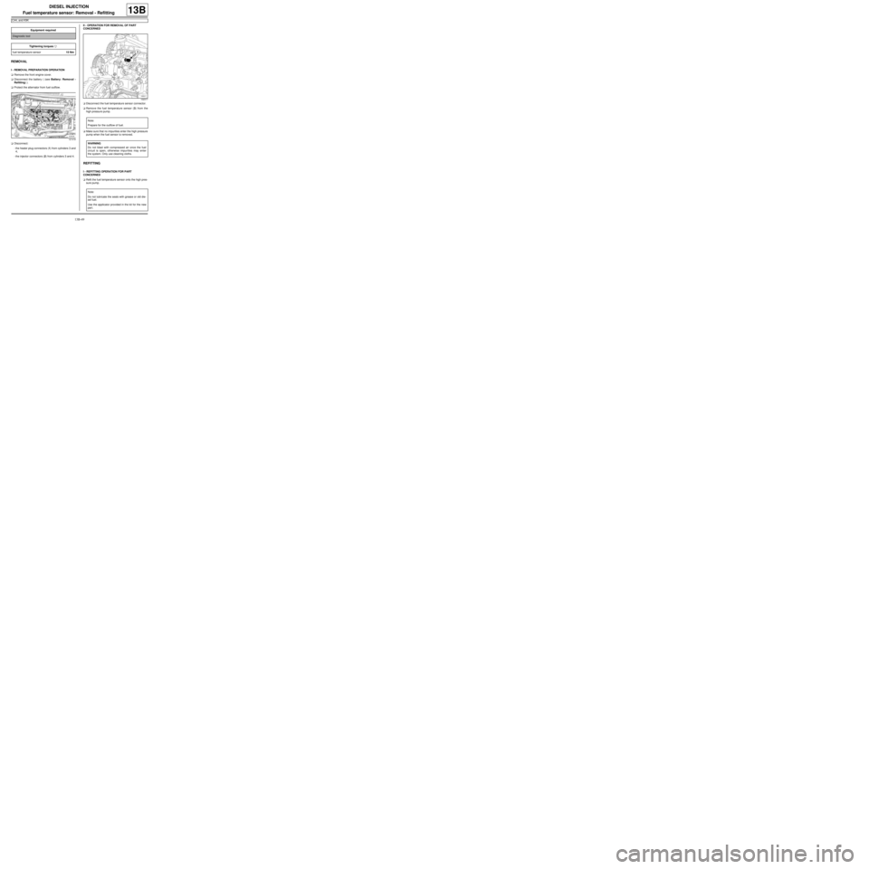
aDisconnect:
-the heater plug connectors (1) from cylinders 3 and
4,
-the injector connectors (2) from cylinders 3 and 4.II - OPERATION FOR REMOVAL OF PART
CONCERNED
aDisconnect the fuel temperature sensor connector.
aRemove the fuel temperature sensor (3) from the
high pressure pump.
aMake sure that no impurities enter the high pressure
pump when the fuel sensor is removed.
REFITTING
I - REFITTING OPERATION FOR PART
CONCERNED
aRefit the fuel temperature sensor onto the high pres-
sure pump. Equipment required
Diagnostic tool
Tightening torquesm
fuel temperature sensor15 Nm
121418
102317
Note:
Prepare for the outflow of fuel.
WARNING
Do not blast with compressed air once the fuel
circuit is open, otherwise impurities may enter
the system. Only use cleaning cloths.
Note:
Do not lubricate the seals with grease or old die-
sel fuel.
Use the applicator provided in the kit for the new
par t.
Page 411 of 652
13B-50
DIESEL INJECTION
Fuel temperature sensor: Removal - Refitting
C44, and K9K
13B
aTorque tighten the fuel temperature sensor (15
Nm).
aConnect the fuel temperature sensor connector.
II - FINAL OPERATION.
aConnect:
-the injector connectors for cylinders 3 and 4,
-the heater plug connectors for cylinders 3 and 4.
aRemove the protection on the alternator to prevent
fuel flowing out.
aConnect the battery ( (see Battery: Removal - Re-
fitting) ).
aStart the engine and check that there are no leaks.
aRefit the engine cover.
aUse the Diagnostic tool to check for an absence of
stored faults; deal with these and clear them as nec-
essary.
Page 412 of 652
13B-51
DIESEL INJECTION
Injector leak flow: Check
K9K
13B
PIECES ET INGREDIENTS POUR LA REPARATION
Ingrédients :
-cleaning cloths,
-set of K9K blanking plugs (DELPHI injection).
CHECK
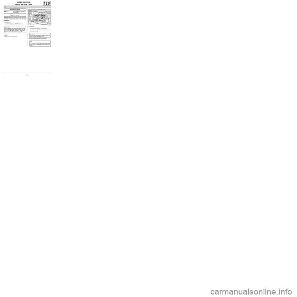
aRemove the front engine cover.aDisconnect:
-the diesel return pipes (1) on the injectors,
-the diesel return pipe (2) on the Venturi fitted on the
high pressure pump.
aFit the correct blanking plug on the Venturi. Special tooling required
Mot. 1711Kit for measuring the injector
fuel flow rate.
Equipment required
Diagnostic tool
IMPORTANT
Consult the safety and cleanliness advice and oper-
ation recommendations before carrying out any
repair (see 13B, Diesel injection, Diesel injec-
tion: Precautions for the repair, page 13B-1) .
121418
WARNING
To avoid any corrosion or damage, protect the
areas on which fuel is likely to r un.
Note:
It is essential to fi t an appropriate blanking plug
to the Venturi to avoid depriming the diesel return
circuit.
Page 413 of 652
13B-52
DIESEL INJECTION
Injector leak flow: Check
K9K
13B
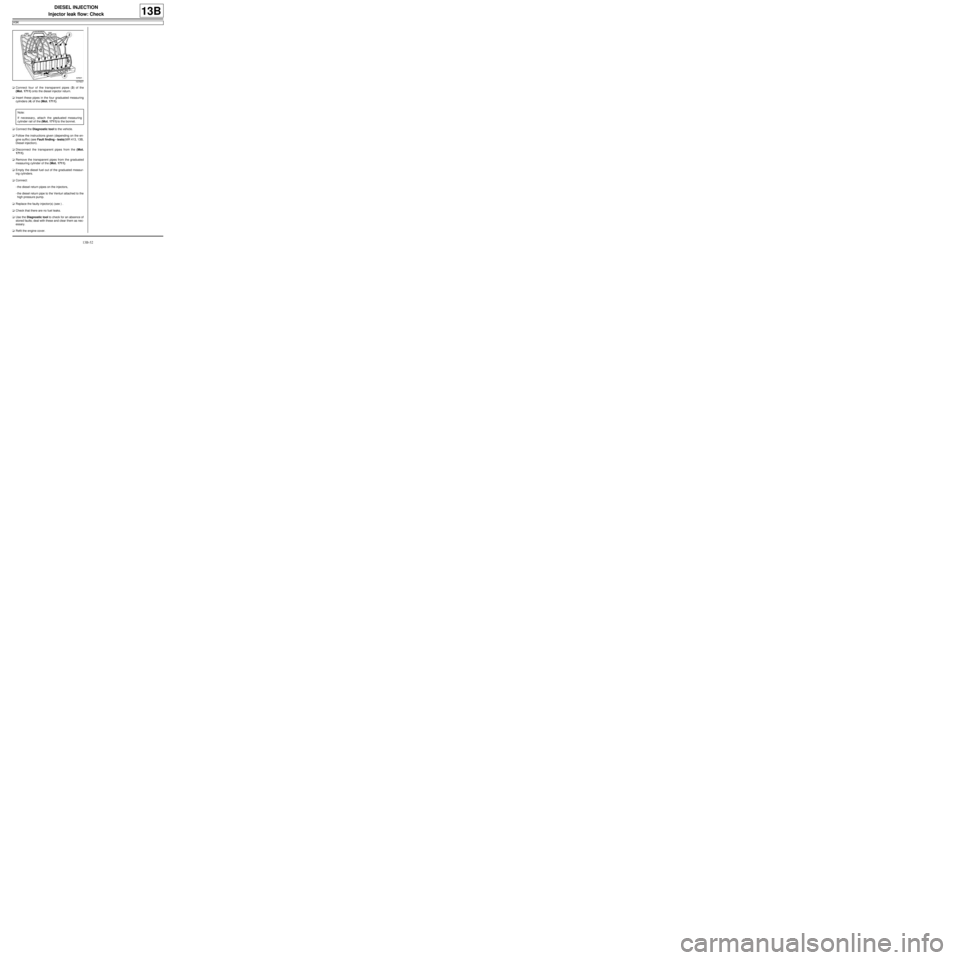
aConnect four of the transparent pipes (3) of the
(Mot. 1711) onto the diesel injector return.
aInsert these pipes in the four graduated measuring
cylinders (4) of the (Mot. 1711).
aConnect the Diagnostic tool to the vehicle.
aFollow the instructions given (depending on the en-
gine suffix) (see Fault finding - tests)(MR 413, 13B,
Diesel injection).
aDisconnect the transparent pipes from the (Mot.
1711).
aRemove the transparent pipes from the graduated
measuring cylinder of the (Mot. 1711).
aEmpty the diesel fuel out of the graduated measur-
ing cylinders.
aConnect:
-the diesel return pipes on the injectors,
-the diesel return pipe to the Venturi attached to the
high pressure pump.
aReplace the faulty injector(s) (see ) .
aCheck that there are no fuel leaks.
aUse the Diagnostic tool to check for an absence of
stored faults; deal with these and clear them as nec-
essary.
aRefit the engine cover.
107637
Note:
If necessary, attach the graduated measuring
cylinder rail of the (Mot. 1711) to the bonnet.
Page 414 of 652
13B-53
DIESEL INJECTION
Accelerometer: Removal - Refitting
K9K
13B
REMOVAL
I - REMOVAL PREPARATION OPERATION
aRemove the front engine cover.
aRemove:
-the dipstick,
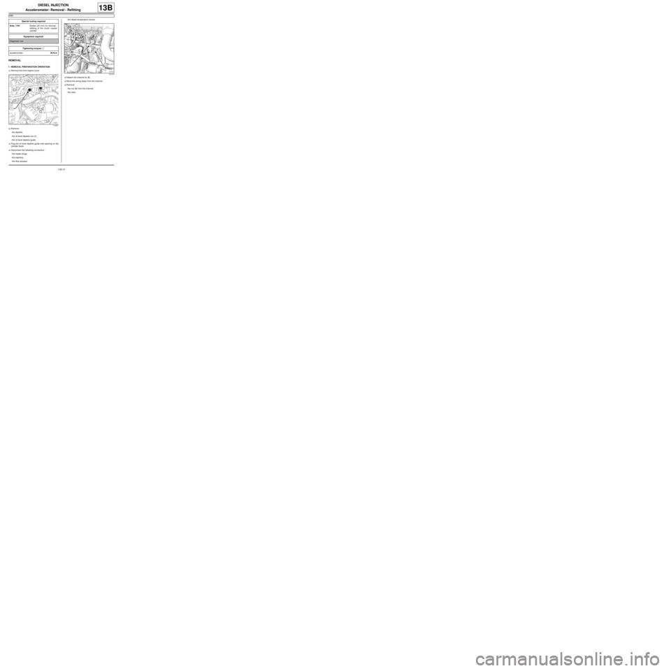
-the oil level dipstick nut (1) ,
-the oil level dipstick guide.
aPlug the oil level dipstick guide inlet opening on the
cylinder block.
aDisconnect the following connectors :
-the heater plugs,
-the injectors,
-the flow actuator,-the diesel temperature sensor.
aDetach the channel at (2) .
aMove the wiring away from the channel.
aRemove:
-the nut (3) from the channel,
-the neck. Special tooling required
Emb. 1797Socket (24 mm) for removal -
refitting of the clutch master
cylinder
Equipment required
Diagnostic tool
Tightening torquesm
accelerometer20 N.m
114527
121419
Page 415 of 652
13B-54
DIESEL INJECTION
Accelerometer: Removal - Refitting
K9K
13B
II - OPERATION FOR REMOVAL OF PART
CONCERNED
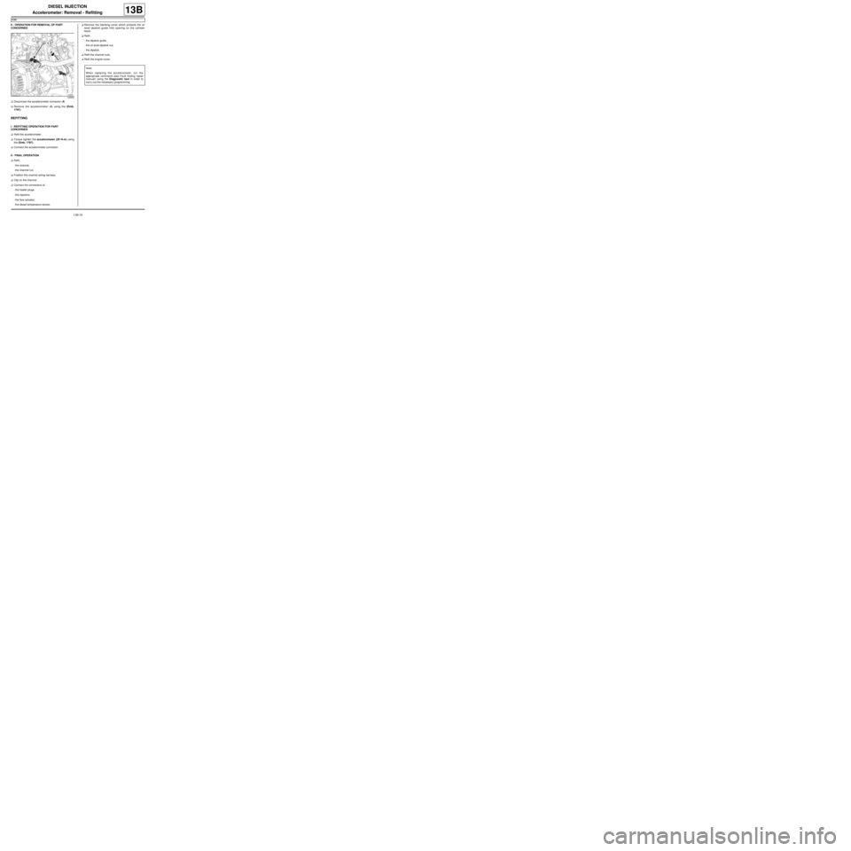
aDisconnect the accelerometer connector (4) .
aRemove the accelerometer (4) using the (Emb.
1797).
REFITTING
I - REFITTING OPERATION FOR PART
CONCERNED
aRefit the accelerometer.
aTorque tighten the accelerometer (20 N.m) using
the (Emb. 1797).
aConnect the accelerometer connector.
II - FINAL OPERATION
aRefit:
-the channel,
-the channel nut.
aPosition the channel wiring harness.
aClip on the channel.
aConnect the connectors of:
-the heater plugs,
-the injectors,
-the flow actuator,
-the diesel temperature sensor.aRemove the blanking cover which protects the oil
level dipstick guide inlet opening on the cylinder
block.
aRefit:
-the dipstick guide,
-the oil level dipstick nut,
-the dipstick.
aRefit the channel nuts.
aRefit the engine cover.
109939
Note:
When replacing the accelerometer, run the
appropriate command (see Fault finding repair
manual) using the Diagnostic tool in order to
carr y out the necessary programming.
Page 417 of 652
13C-2
PREHEATING
Heater plugs: Removal - Refitting
K9K
13C
REMOVAL
I - REMOVAL PREPARATION OPERATION
aRemove the front engine cover.
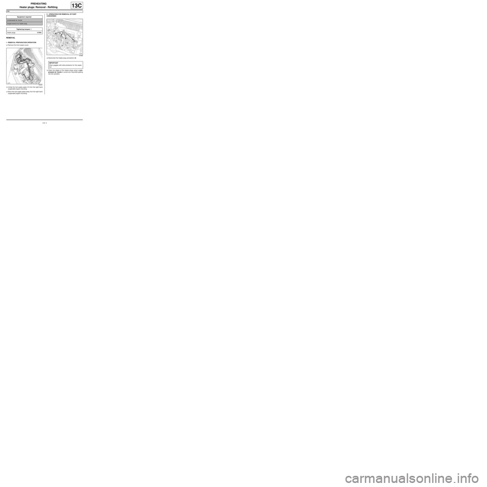
aUnclip the fuel supply pipes (1) from the right-hand
suspended engine mounting.
aMove the fuel supply pipes away from the right-hand
suspended engine mounting.II - OPERATION FOR REMOVAL OF PART
CONCERNED
aDisconnect the heater plug connectors (2) .
aClean the edges of the heater plugs using a com-
pressed air nozzle to avoid any impurities getting
into the cylinders. Equipment required
compressed air nozzle
hinged wrench for heater plug
Tightening torquesm
heater plugs15 Nm
120045
127895
IMPORTANT
Wear goggles with side protectors for this opera-
tion.
Page 418 of 652
13C-3
PREHEATING
Heater plugs: Removal - Refitting
K9K
13C
a
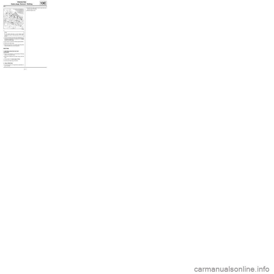
aLoosen the heater plugs (3) using a 10 mm long ra-
dio socket connected to a universal joint or a hinged
wrench for heater plug.
aUse a hose to unscrew the heater plugscompletely.
aRemove the heater plugs.
aBlock the plug wells on the cylinder head using clean
cloths throughout the removal operation.
REFITTING
I - REFITTING OPERATION FOR PART
CONCERNED
aRemove the protection on the openings of the plug
well(s) on the cylinder head.
aBolt without tightening the heater plugs using the
hose.
aTorque tighten the heater plugs (15 Nm).
aConnect the heater plug connectors.
II - FINAL OPERATION.
aFit the fuel pipes on the right-hand suspended en-
gine mounting.aClip the fuel supply pipes onto the right-hand sus-
pended engine mounting.
aRefit the engine cover.
127905
Note:
If the heater plugs jam, use the heater plug
removal tool (see ) (Technical Note 5197A, 06A,
Tools).