wheel bolts RENAULT TWINGO RS 2009 2.G Engine And Peripherals Repair Manual
[x] Cancel search | Manufacturer: RENAULT, Model Year: 2009, Model line: TWINGO RS, Model: RENAULT TWINGO RS 2009 2.GPages: 652
Page 247 of 652
11A-130
TOP AND FRONT OF ENGINE
Cylinder head: Removal - Refitting
D4F, and 780 or 782
11A
REMOVAL
I - REMOVAL PREPARATION OPERATION
aPosition the vehicle on a two-post lift (see Vehicle:
Towing and lifting) (02A, Lifting equipment).
aDisconnect the battery (see Battery: Removal - Re-
fitting) (80A, Battery).
aRemove:
-the front right-hand wheel (see Wheel: Removal -
Refitting) (35A, Wheels and tyres),
-the front right-hand wheel arch liner (see Front
wheel arch liner: Removal - Refitting) (55A, Ex-
terior protection).
aDrain the cooling system (see 19A, Cooling, Cool-
ing system: Draining - Refilling, page 19A-9) .
aRemove:
-the air filter unit (see 12A, Fuel mixture, Air filter
unit: Removal - Refitting, page 12A-13) ,
-the upstream oxygen sensor (see 17B, Petrol in-
jection, Oxygen sensors: Removal - Refitting,
page 17B-13) ,
-the ignition coil (see 17A, Ignition, Coils: Remov-
al - Refitting, page 17A-1) ,-the rocker cover (see 11A, Top and front of en-
gine, Rocker cover: Removal - Refitting, page
11A-66) ,
-the catalytic converter (see 19B, Exhaust, Cata-
lytic converter: Removal - Refitting, page 19B-
12) ,
-the turbocharger oil pipes (see 12B, Turbocharg-
ing, Turbocharger oil pipe: Removal - Refitting,
page 12B-12) .
aUnclip the wiring from the turbocharger coolant rigid
pipe bracket.
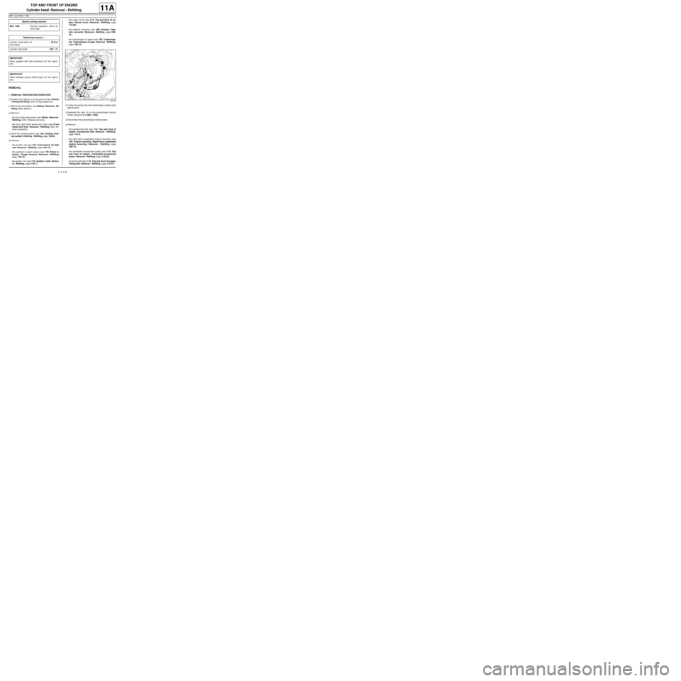
aSeparate the clips (1) on the turbocharger cooling
hoses using the tool (Mot. 1448).
aDisconnect the turbocharger cooling hoses.
aRemove:
-the accessories belt (see 11A, Top and front of
engine, Accessories belt: Removal - Refitting,
page 11A-3) ,
-the right-hand suspended engine mounting (see
19D, Engine mounting, Right-hand suspended
engine mounting: Removal - Refitting, page
19D-13) ,
-the crankshaft accessories pulley (see 11A, Top
and front of engine, Crankshaft accessories
pulley: Removal - Refitting, page 11A-20) ,
-the timing belt (see 11A, Top and front of engine,
Timing belt: Removal - Refitting, page 11A-27) . Special tooling required
Mot. 1448Remote operation pliers for
hose clips .
Tightening torquesm
cylinder head bolts (ini-
tial torque)20 N.m
cylinder head bolts230˚ ±± ± ±
6˚
IMPORTANT
Wear goggles with side protectors for this opera-
tion.
IMPORTANT
Wear leaktight gloves (Nitrile type) for this opera-
tion.
121773
Page 251 of 652
11A-134
TOP AND FRONT OF ENGINE
Cylinder head: Removal - Refitting
D4F, and 780 or 782
11A
-the turbocharging solenoid valve connector to the
turbocharger.
aTighten the compressor discharge valve air pipe
clip.
aPosition the intercooler outlet air pipe on the throttle
valve.
aRefit:
-the intercooler air outlet pipe bolts,
-the timing belt (see 11A, Top and front of engine,
Timing belt: Removal - Refitting, page 11A-27) ,
-the crankshaft accessories pulley (see 11A, Top
and front of engine, Crankshaft accessories
pulley: Removal - Refitting, page 11A-20) ,
-the right-hand suspended engine mounting (see
19D, Engine mounting, Right-hand suspended
engine mounting: Removal - Refitting, page
19D-13) ,
-the accessories belt (see 11A, Top and front of
engine, Accessories belt: Removal - Refitting,
page 11A-3) .
aConnect the turbocharger cooling hoses.
aFit the turbocharger cooling hose clips using the tool
(Mot. 1448).
aClip the wiring onto the turbocharger coolant rigid
pipe bracket.
aRefit:
-the turbocharger oil pipes (see 12B, Turbocharg-
ing, Turbocharger oil pipe: Removal - Refitting,
page 12B-12) ,
-the catalytic converter (see 19B, Exhaust, Cata-
lytic converter: Removal - Refitting, page 19B-
12) ,
-the rocker cover (see 11A, Top and front of en-
gine, Rocker cover: Removal - Refitting, page
11A-66) ,
-the ignition coil (see 17A, Ignition, Coils: Remov-
al - Refitting, page 17A-1) ,
-the upstream oxygen sensor (see 17B, Petrol in-
jection, Oxygen sensors: Removal - Refitting,
page 17B-13) ,
-the air filter unit (see 12A, Fuel mixture, Air filter
unit: Removal - Refitting, page 12A-13) .
aFill and bleed the cooling system (see 19A, Cool-
ing, Cooling system: Draining - Refilling, page
19A-9) .
aConnect the battery (see Battery: Removal - Refit-
ting) (80A, Battery).aRefit:
-the front right-hand wheel arch liner (see Front
wheel arch liner: Removal - Refitting) (55A, Ex-
terior protection),
-the front right-hand wheel (see Wheel: Removal -
Refitting) (35A, Wheels and tyres).
Page 257 of 652

11A-140
TOP AND FRONT OF ENGINE
Camshaft seal, timing end: Removal - Refitting
K9K
11A
III - FINAL OPERATION.
aRefit:
-the camshaft pulley hub,
-the camshaft pulley hub nut, locking it using the
(Mot. 799-01).
aTorque and angle tighten using a cylinder head
bolt tightening gauge (angular measuring type)
the camshaft hub nut ( 30 Nm + 86˚ ±± ± ±
6˚).
aRefit the camshaft pulley wheel.
aFit the camshaft pulley wheel bolts, without tighten-
ing them.
aRefit:
-the timing belt (see 11A, Top and front of engine,
Timing belt: Removal - Refitting, page 11A-27) ,
-the camshaft position sensor (see 13B, Diesel in-
jection, Camshaft position sensor: Removal -
Refitting, page 13B-14) ,
-the crankshaft accessories pulley (see 11A, Top
and front of engine, Crankshaft accessories
pulley: Removal - Refitting, page 11A-20) ,
-the accessories belt (see 11A, Top and front of
engine, Accessories belt: Removal - Refitting,
page 11A-3) ,
-the right-hand suspended engine mounting (see
19D, Engine mounting, Right-hand suspended
engine mounting: Removal - Refitting, page
19D-13) ,
-the lower engine tie-bar (see 19D, Engine mount-
ing, Lower engine tie-bar: Removal - Refitting,
page 19D-18) ,
-the front upper cross member (see Front upper
cross member: Removal - Refitting) (MR 412,
42A, Upper front structure),
-the halogen headlights (see Halogen headlight:
Removal - Refitting) (MR 411, 80B, Halogen
headlights),
-the front bumper (see Front bumper: Removal -
Refitting) (MR 412, 55A, Exterior protection),
-the front right-hand wheel arch liner (see Front
wheel arch liner: Removal - Refitting) (MR 412,
55A, Exterior protection),
-the front right-hand wheel (see Wheel: Removal -
Refitting) (MR 411, 35A, Wheels and tyres),
-the scoop under the scuttle panel grille (see Scoop
under the scuttle panel grille: Removal - Refit-
ting) (MR 412, 56A, Exterior equipment),-the scuttle panel grille (see Scuttle panel grille:
Removal - Refitting) (MR 412, 56A, Exterior
equipment),
-the windscreen wiper arms (see Windscreen wip-
er arm: Removal - Refitting) (MR 411, 85A, Wip-
ers - Washers).
aConnect the battery (see Battery: Removal - Refit-
ting) (see MR 411, 80A, Battery).
Page 284 of 652
12A-19
FUEL MIXTURE
Air resonator: Removal - Refitting
K4M
12A
REMOVAL
I - REMOVAL PREPARATION OPERATION
aPosition the vehicle on a two-post lift (see Vehicle:
Towing and lifting) (02A, Lifting equipment).
aRemove:
-the engine undertray,
-the front left-hand wheel (see Wheel: Removal -
Refitting) (35A, Wheels and tyres),
-the front left-hand wheel arch liner (see Front
wheel arch liner: Removal - Refitting) (55A, Ex-
terior protection).
II - REMOVAL OPERATION
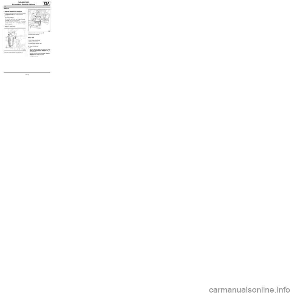
aRemove the air resonator mounting bolts (1) .aDisconnect the air resonator pipe (2) .
aRemove the air resonator .
REFITTING
I - REFITTING OPERATION
aRefit the air resonator.
aConnect the air resonator pipe.
II - FINAL OPERATION
aRefit:
-the front left-hand wheel arch liner (see Front
wheel arch liner: Removal - Refitting) (55A, Ex-
terior protection),
-the front left-hand wheel (see Wheel: Removal -
Refitting) (35A, Wheels and tyres),
-the engine undertray.
131764
131765
Page 320 of 652
12A-55
FUEL MIXTURE
Exhaust manifold: Removal - Refitting
K4M
12A
REMOVAL
I - REMOVAL PREPARATION OPERATION
aPosition the vehicle on a two-post lift (see Vehicle:
Towing and lifting) (02A, Lifting equipment).
aDisconnect the battery (see Battery: Removal - Re-
fitting) (80A, Battery).
aRemove:
-the engine undertray,
-the front right-hand wheel (see Wheel: Removal -
Refitting) (35A, Wheels and tyres),
-the windscreen wiper arms (see Windscreen wip-
er arm: Removal - Refitting) (85A, Wiping -
Washing),
-the scuttle panel grille (see Scuttle panel grille:
Removal - Refitting) (56A, Exterior equipment),
-the scoop under the scuttle panel grille (see Scoop
under the scuttle panel grille: Removal - Refit-
ting) (56A, Exterior equipment).
aDrain the gearbox (see Manual gearbox oils:
Draining - Filling) (21A, Manual gearbox).aRemove:
-the front right-hand wheel driveshaft (see Front
right-hand driveshaft: Removal - Refitting)
(29A, Driveshafts),
-the lower engine tie-bar (see 19D, Engine mount-
ing, Lower engine tie-bar: Removal - Refitting,
page 19D-18) ,
-the upstream expansion chamber (see 19B, Ex-
haust, Expansion chamber: Removal - Refit-
ting, page 19B-23) .
aRemove:
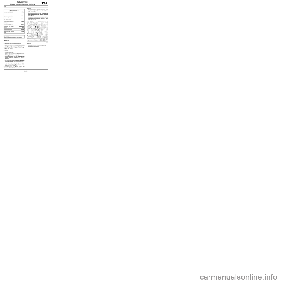
-the bolts (1) from the driveshaft relay bearing,
-the driveshaft relay bearing. Tightening torquesm
exhaust manifold studs9 N.m
heat shield bolts12 N.m
upstream and down-
stream oxygen sensors44 N.m
strut mounting bolt on
the cylinder block75 N.m
upstream strut bolt (ini-
tial torque)14 N.m
exhaust manifold nuts26 N.m
upstream and down-
streamstrut bolts44
N.m
upstream strut bolts44 N.m
driveshaft relay bearing
bolts21 N.m
IMPORTANT
Wear cut-resistant gloves during the operation.
131770
Page 325 of 652
12A-60
FUEL MIXTURE
Exhaust manifold: Removal - Refitting
K4M
12A
-the driveshaft relay bearing.
aTorque tighten the driveshaft relay bearing bolts
(21 N.m).
aRefit:
-the upstream expansion chamber (see 19B, Ex-
haust, Expansion chamber: Removal - Refit-
ting, page 19B-23) ,
-the lower engine tie-bar (see 19D, Engine mount-
ing, Lower engine tie-bar: Removal - Refitting,
page 19D-18) ,
-the front right-hand wheel driveshaft (see Front
right-hand driveshaft: Removal - Refitting)
(29A, Driveshafts).
aFill the gearbox (see Manual gearbox oils: Drain-
ing - Filling) (21A, Manual gearbox).
aRefit:
-the scoop under the scuttle panel grille (see Scoop
under the scuttle panel grille: Removal - Refit-
ting) (56A, Exterior equipment),
-the scuttle panel grille (see Scuttle panel grille:
Removal - Refitting) (56A, Exterior equipment),
-the windscreen wiper arms (see Windscreen wip-
er arm: Removal - Refitting) (85A, Wiping -
Washing),
-the front right-hand wheel (see Wheel: Removal -
Refitting) (35A, Wheels and tyres),
-the engine undertray.
aConnect the battery (see Battery: Removal - Refit-
ting) (80A, Battery).
Page 333 of 652
12B-8
TURBOCHARGING
Turbocharger: Removal - Refitting
D4F, and 780 or 782
12B
REMOVAL
I - REMOVAL PREPARATION OPERATION
aPosition the vehicle on a two-post lift (see Vehicle:
Towing and lifting) (02A, Lifting equipment).
aDisconnect the battery (see Battery: Removal - Re-
fitting) (80A, Battery).
aRemove the engine undertray.
aDrain the manual gearbox (see Manual gearbox
oils: Draining - Filling) (21A, Manual gearbox).
aRemove:
-the air filter unit (see 12A, Fuel mixture, Air filter
unit: Removal - Refitting, page 12A-13) ,
-the upstream oxygen sensor (see 17B, Petrol in-
jection, Oxygen sensors: Removal - Refitting,
page 17B-13) ,
-the lower engine tie-bar (see 19D, Engine mount-
ing, Lower engine tie-bar: Removal - Refitting,
page 19D-18) ,
-the front right-hand wheel driveshaft (see Front
right-hand driveshaft: Removal - Refitting)
(29A, Driveshafts),
-the catalytic converter (see 19B, Exhaust, Cata-
lytic converter: Removal - Refitting, page 19B-
12) .II - OPERATION FOR REMOVAL OF PART
CONCERNED
aRemove the turbocharger oil return pipe (see 12B,
Turbocharging, Turbocharger oil pipe: Removal
- Refitting, page 12B-12) .
aFit the tools (Ms. 583) onto the turbocharger cooling
hoses (6) .
aRemove the turbocharger cooling hose clips using
the tool (Mot. 1448).
aDisconnect the turbocharger cooling hoses.
aRemove the turbocharger cooling pipe strut bolt (7) .
aRemove the turbocharger oil supply pipe (see 12B,
Turbocharging, Turbocharger oil pipe: Removal
- Refitting, page 12B-12) . Special tooling required
Ms. 583Pipe clamps .
Mot. 1448Remote operation pliers for
hose clips .
Tightening torquesm
turbocharger nuts21 N.m
turbocharger cooling
pipe hollow bolts30 N.m
turbocharger cooling
pipe bracket bolts10 N.m
IMPORTANT
Wear cut-resistant gloves during the operation.121773
Page 343 of 652
12B-18
TURBOCHARGING
Intercooler: Removal - Refitting
D4F, and 780 or 782 – K9K, and 718
12B
REMOVAL
I - REMOVAL PREPARATION OPERATION
aPosition the vehicle on a two-post lift (see Vehicle:
Towing and lifting) (02A, Lifting equipment).
aRemove:
-the front wheels (see Wheel: Removal - Refitting)
(35A, Wheels and tyres),
-the front wheel arch liners (see Front wheel arch
liner: Removal - Refitting) (55A, Exterior protec-
tion),
-the front bumper (see Front bumper: Removal -
Refitting) (55A, Exterior protection).
II - OPERATION FOR REMOVAL OF PART
CONCERNED
aRemove the intercooler bolts (1) .
aLoosen the clip on the intercooler air outlet pipe (2) .
aDisconnect the intercooler air outlet pipe.
aUnclip the turbocharger air outlet pipe (3) .
aDisconnect the turbocharger air outlet pipe.
aRemove:
-the intercooler,
-the air deflector clips,
-the air deflector,
-the metal mounting.
REFITTING
I - REFITTING PREPARATION OPERATION
aCheck that the intercooler is not full of oil. In this
case, clean it with cleaning agent and let it dry (see
Vehicle: Parts and consumables for the repair)
(04B, Consumables - Products).
II - REFITTING OPERATION FOR PART
CONCERNED
aRefit:
-the metal mounting,
-the air deflector,
-the air deflector clips,
-the intercooler.
aConnect the turbocharger air outlet pipe.
aClip on the turbocharger air outlet pipe.
aConnect the intercooler air outlet pipe.
aTighten the clip on the intercooler outlet pipe.
aRefit the intercooler bolts.
III - FINAL OPERATION
aRefit:
-the front bumper (see Front bumper: Removal -
Refitting) (55A, Exterior protection),
-the front wheel arch liners (see Front wheel arch
liner: Removal - Refitting) (55A, Exterior protec-
tion),
-the front wheels (see Wheel: Removal - Refitting)
(35A, Wheels and tyres).
122830
Page 424 of 652
14A-6
ANTIPOLLUTION
Fuel vapour absorber: Removal - Refitting
D4F, and SOUTH AFRICA
14A
REMOVAL
I - REMOVAL PREPARATION OPERATION
aPosition the vehicle on a two-post lift (see Vehicle:
Towing and lifting)
aDisconnect the battery (see Battery: Removal - Re-
fitting)
aRemove the rear left-hand wheel (see Wheel: Re-
moval - Refitting)
aRemove the rear left-hand wheel arch liner (see ) II - OPERATION FOR REMOVAL OF PART
CONCERNED
aUnclip the petrol vapour absorber pipe.
aRemove:
-the petrol vapour absorber bolts.
-the petrol vapour absorber.
REFITTING
REFITTING OPERATION FOR PART CONCERNED
aRefit.
-the petrol vapour absorber.
-the petrol vapour absorber bolts
aClip on the petrol vapour absorber pipe.
FINAL OPERATION
aRefit the rear left-hand wheel arch liner (see )
aRefit the rear left-hand wheel (see Wheel: Removal
- Refitting)
aReconnect the battery (see Battery: Removal - Re-
fitting) IMPORTANT
During this oper ation, be sure to:
-refrain from smoking or bringing red hot objects
close to the working area,
-be careful of fuel splashes when disconnecting the
union.
IMPORTANT
Wear goggles with side protectors for this opera-
tion.
IMPORTANT
Wear leaktight gloves (Nitrile type) for this opera-
tion.
WARNING
To avoid any corrosion or damage, protect the
areas on which fuel is likely to run.
WARNING
Keep the pipe unions away from contaminated
areas.
WARNING
To prevent impurities from entering the circuit, place
protective plugs on all fuel circuit components
exposed to the open air.
143884
Page 440 of 652
16A-1
STARTING - CHARGING
Alternator: Removal - Refitting
D4F or D7F, and STANDARD HEATING
16A
REMOVAL
I - REMOVAL PREPARATION OPERATION
aDisconnect the battery (see ) (MR 411, 80A, Bat-
tery).
aRemove:
-the front right-hand wheel (see Wheel: Removal -
Refitting) (MR 411, 35A, Wheels and tyres),
-the front right-hand wheel arch liner (see Front
wheel arch liner: Removal - Refitting) (MR 412,
55A, Exterior protection).
aUndo the lower bolt on the sub-frame tie-rod.
aRemove the upper bolt from the sub-frame tie-rod.
aRemove the sub-frame tie-rod.
aRemove the accessories belt (see 11A, Top and
front of engine, Accessories belt: Removal - Re-
fitting, page 11A-3) . Tightening torquesm
alter nator bolts25 Nm
sub-frame tie-rod lower
bolt62 Nm
sub-frame tie-rod upper
bolt21 Nm