ABS RENAULT TWINGO RS 2009 2.G Engine And Peripherals Workshop Manual
[x] Cancel search | Manufacturer: RENAULT, Model Year: 2009, Model line: TWINGO RS, Model: RENAULT TWINGO RS 2009 2.GPages: 652
Page 5 of 652
Contents
13C PREHEATING
Pre-postheating unit:
Removal - Refitting 13C-1
Heater plugs: Removal -
Refitting 13C-2
14A ANTIPOLLUTION
Oil vapour rebreathing
circuit: Descriptions 14A-1
Fuel vapour recirculation
circuit: Operating diagram 14A-2
Fuel vapour recirculation
circuit: Check 14A-3
Fuel vapour absorber:
Removal - Refitting 14A-4
Fuel vapour absorber: Check 14A-7
Fuel vapour absorber bleed
solenoid valve: Removal -
Refitting 14A-8
Exhaust gas recirculation
solenoid valve: Removal -
Refitting 14A-10
Exhaust gas cooler: Removal
- Refitting 14A-11
Exhaust gas recirculation
assembly: Removal -
Refitting 14A-15
Exhaust gas recirculation
rigid pipe: Removal -
Refitting 14A-19
16A STARTING - CHARGING
Alternator: Removal -
Refitting 16A-1
Star ter: Removal - Refitting 16A-10
Alternator pulley: Removal -
Refitting 16A-1717A IGNITION
Coils: Removal - Refitting 17A-1
Plugs: Removal - Refitting 17A-12
17B PETROL INJECTION
Petrol injection: List and
location of components 17B-1
Oxygen sensors: Removal -
Refitting 17B-13
Petrol injection computer:
Removal - Refitting 17B-20
Pinking sensor: Removal -
Refitting 17B-23
Crankshaft position sensor:
Removal - Refitting 17B-25
Injector rail - Injectors:
Removal - Refitting 17B-27
19A COOLING
Engine cooling system:
Specifications 19A-1
Engine cooling system:
Check 19A-2
Engine cooling circuit: List
and location of components 19A-4
Engine cooling system:
Operating diagram 19A-5
Cooling system: Draining -
Refilling 19A-9
Cooling radiator: Removal -
Refitting 19A-12
Coolant pump: Removal -
Refitting 19A-24
Thermostat: Removal -
Refitting 19A-34
Water chamber: Removal -
Refitting 19A-40
Page 80 of 652
10A-74
ENGINE AND CYLINDER BLOCK ASSEMBLY
Engine - gearbox assembly: Removal - Refitting
D4F or D7F
10A
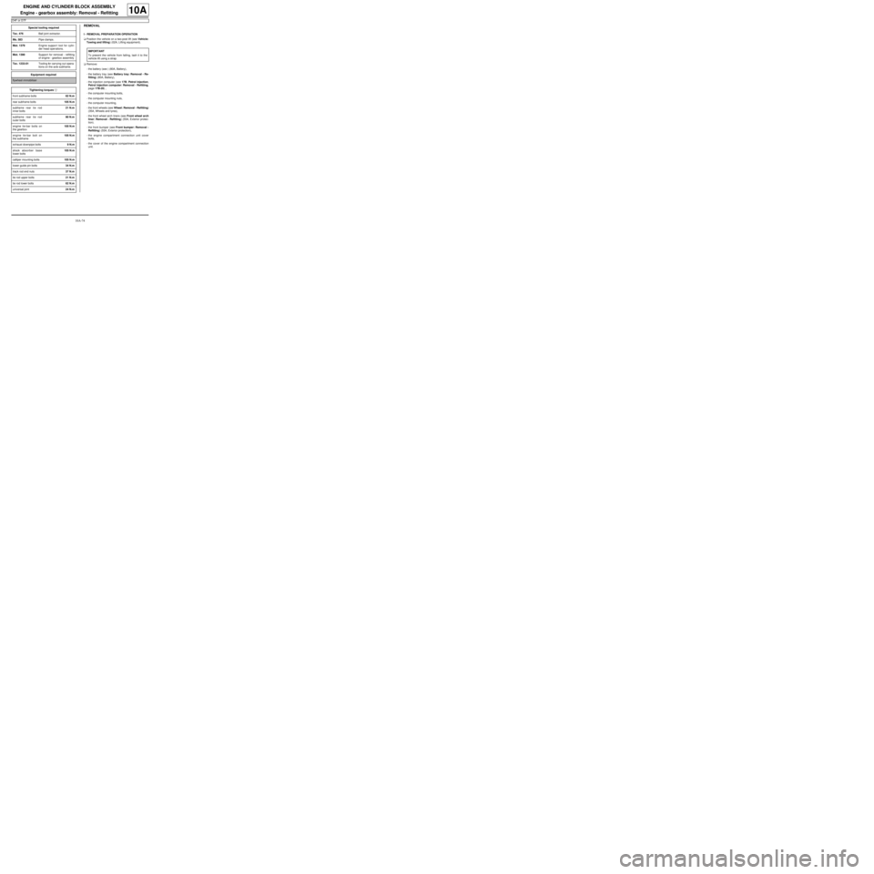
REMOVAL
I - REMOVAL PREPARATION OPERATION
aPosition the vehicle on a two-post lift (see Vehicle:
Towing and lifting) (02A, Lifting equipment).
aRemove:
-the battery (see ) (80A, Battery),
-the battery tray (see Battery tray: Removal - Re-
fitting) (80A, Battery),
-the injection computer (see 17B, Petrol injection,
Petrol injection computer: Removal - Refitting,
page 17B-20) ,
-the computer mounting bolts,
-the computer mounting nuts,
-the computer mounting,
-the front wheels (see Wheel: Removal - Refitting)
(35A, Wheels and tyres),
-the front wheel arch liners (see Front wheel arch
liner: Removal - Refitting) (55A, Exterior protec-
tion).
-the front bumper (see Front bumper: Removal -
Refitting) (55A, Exterior protection),
-the engine compartment connection unit cover
bolts,
-the cover of the engine compartment connection
unit. Special tooling required
Tav. 476Ball joint extractor.
Ms. 583Pipe clamps .
Mot. 1379Engine suppor t tool for cylin-
der head oper ations.
Mot. 1390Suppor t for removal - refitting
of engine - gearbox assembly
Tav. 1233-01Tooling for carrying out opera-
tions on the axle subframe.
Equipment required
flywheel immobiliser
Tightening torquesm
front subframe bolts62 N.m
rear subframe bolts105 N.m
subframe rear tie rod
inner bolts21 N.m
subframe rear tie rod
outer bolts90 N.m
engine tie-bar bolts on
the gearbox105 N.m
engine tie-bar bolt on
the subframe105 N.m
exhaust downpipe bolts9 N.m
shock absorber base
lower bolts105 N.m
calliper mounting bolts105 N.m
lower guide pin bolts34 N.m
track rod end nuts37 N.m
tie rod upper bolts21 N.m
tie rod lower bolts62 N.m
universal joint24 N.m
IMPORTANT
To prevent the vehicle from falling, lash it to the
vehicle lift using a strap.
Page 84 of 652
10A-78
ENGINE AND CYLINDER BLOCK ASSEMBLY
Engine - gearbox assembly: Removal - Refitting
D4F or D7F
10A
aDrain the coolant circuit (see Refrigerant circuit:
Draining - Filling) .
aRemove:
-the air conditioning pipe bolts on the compressor,
-the air conditioning pipe bolt on the dehydrator res-
ervoir.
aDisconnect the air conditioning pressostat connec-
tor.
a
aDisconnect the fuel supply pipe union.
aInsert the blanking plugs.
aUnclip the fuel pipe on the upper timing cover.aSet the wheels straight ahead.
aPosition the flywheel immobiliser.
aRemove the cover from the universal joint (do not
keep).
aRemove the universal joint bolt (do not keep).
aRemove the universal joint from the steering box.
aDetach the electrical wiring on the cross member.
aLoosen the tie rod lower bolts.
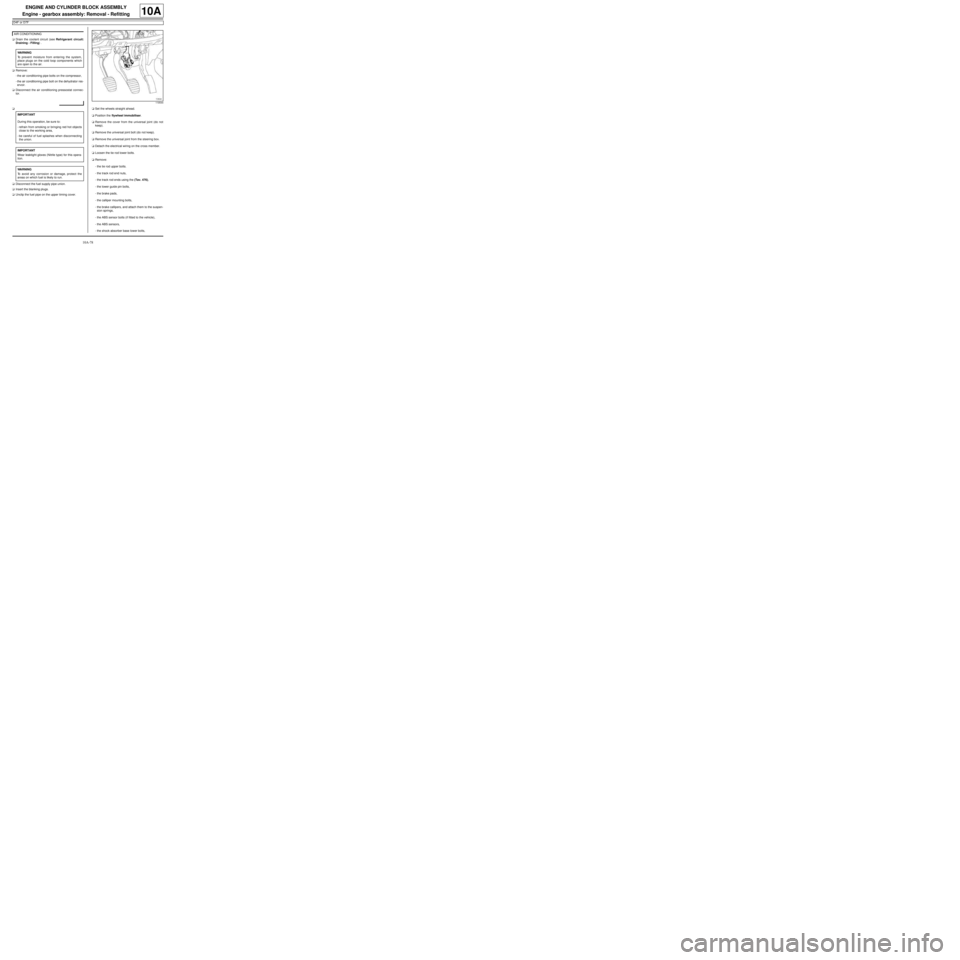
aRemove:
-the tie rod upper bolts.
-the track rod end nuts,
-the track rod ends using the (Tav. 476),
-the lower guide pin bolts,
-the brake pads,
-the calliper mounting bolts,
-the brake callipers, and attach them to the suspen-
sion springs,
-the ABS sensor bolts (if fitted to the vehicle),
-the ABS sensors,
-the shock absorber base lower bolts, AIR CONDITIONING
WARNING
To prevent moisture from entering the system,
place plugs on the cold loop components which
are open to the air.
IMPORTANT
During this operation, be sure to:
-refrain from smoking or bringing red hot objects
close to the working area,
-be careful of fuel splashes when disconnecting
the union.
IMPORTANT
Wear leaktight gloves (Nitrile type) for this opera-
tion.
WARNING
To avoid any corrosion or damage, protect the
areas on which fuel is likely to run.
119544
Page 89 of 652
10A-83
ENGINE AND CYLINDER BLOCK ASSEMBLY
Engine - gearbox assembly: Removal - Refitting
D4F or D7F
10A
aTorque tighten:
-the front subframe bolts (62 N.m),
-the rear subframe bolts (105 N.m),
-the subframe rear tie rod inner bolts (21 N.m),
-the subframe rear tie rod outer bolts (90 N.m),
-the engine tie-bar bolts on the gearbox (105
N.m),
-the engine tie-bar bolt on the subframe (105
N.m).
aRefit the control cables onto the gearbox.
aRemove the blanking plugs from the openings.
aClip the clutch pipe onto the gearbox.
aConnect the clutch slave cylinder.
aRemove the hose clamp (Ms. 583).
aBleed the clutch circuit (see Clutch circuit: Bleed) .
aRefit the gear control linkage.
aAttach the gear control linkage to:
-the gear lever,
-the control lever on the gearbox.
aRefit:
-the heat shield,
-the heat shield bolts.
aRefit the clutch control cable on the manual gearbox.
aRefit the catalytic converter (see 19B, Exhaust,
Catalytic converter: Removal - Refitting, page
19B-12) .aRefit the exhaust downpipe.
aFit the clip.
aTighten the intermediate pipe clip.
aRefit the exhaust downpipe bolts.
aTorque tighten the exhaust downpipe bolts (9
N.m).
aRefit:
-the shock absorber base lower bolts,
-the ABS sensors,
-the ABS sensor bolts (if fitted to the vehicle),
-the brake callipers,
-the calliper mounting bolts,
-the brake pads,
-the lower guide pin bolts,
-track rod ends,
-the track rod end nuts,
-the tie rod upper bolts.
aTorque tighten:
-the shock absorber base lower bolts (105 N.m ),
-the calliper mounting bolts (105 N.m),
-the lower guide pin bolts (34 N.m),
-the track rod end nuts (37 N.m),
-the tie rod upper bolts (21 N.m),
-the tie rod lower bolts (62 N.m).
aClip the electrical wiring on to the cross member.
aFit the steering box universal joint.
aRefit the universal joint bolt.
aTorque tighten the universal joint (24 N.m).
aRemove the flywheel immobiliser.
aClip the fuel pipe on to the upper timing cover.
aConnect the fuel supply pipe union.
aConnect the air conditioning pressostat connector. JH3
JB1 or JH1
D4F, and 772 – D7F
D4F, and 780 or 782
AIR CONDITIONING
Page 104 of 652
10A-98
ENGINE AND CYLINDER BLOCK ASSEMBLY
Engine - gearbox assembly: Removal - Refitting
K4M
10A
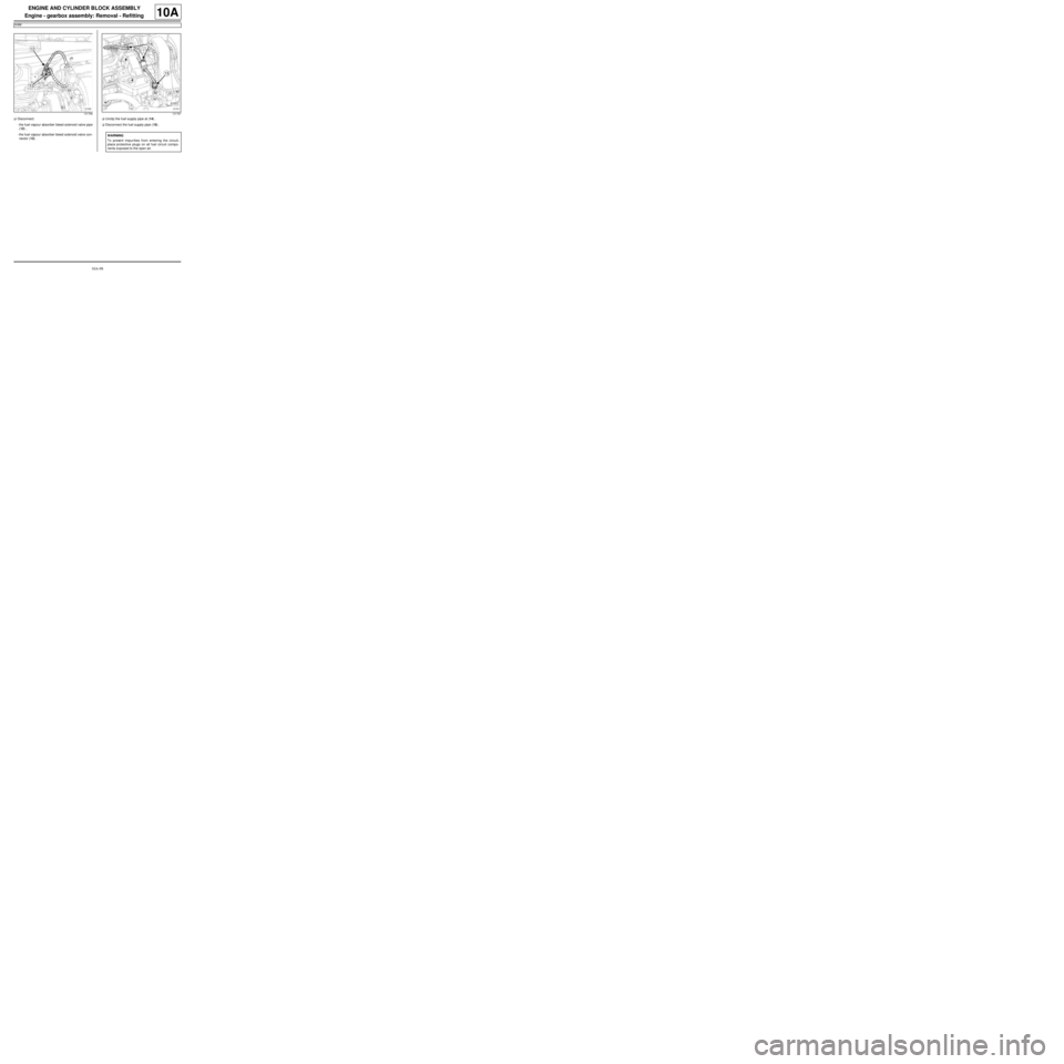
aDisconnect:
-the fuel vapour absorber bleed solenoid valve pipe
(12) ,
-the fuel vapour absorber bleed solenoid valve con-
nector (13) .aUnclip the fuel supply pipe at (14) .
aDisconnect the fuel supply pipe (15) .
131766131767
WARNING
To prevent impur ities from entering the circuit,
place protective plugs on all fuel circuit compo-
nents exposed to the open air.
Page 109 of 652
10A-103
ENGINE AND CYLINDER BLOCK ASSEMBLY
Engine - gearbox assembly: Removal - Refitting
K4M
10A
-the rubber pad mounting from the suspended en-
gine mounting on the gearbox.
aRemove the right-hand suspended engine mounting
(see 19D, Engine mounting, Right-hand sus-
pended engine mounting: Removal - Refitting,
page 19D-13) .
aLift the vehicle to remove the "engine and gearbox"
assembly.
REFITTING
I - REFITTING PREPARATION OPERATION
aFor standard engine replacement (see Standard re-
placement) (Technical Note 6023A, 10A, Engine
and peripherals).
II - REFITTING OPERATION
aPosition the "engine and gearbox" assembly in the
body.
aRefit the right-hand suspended engine mounting
(see 19D, Engine mounting, Right-hand sus-
pended engine mounting: Removal - Refitting,
page 19D-13) .
aRefit the rubber pad mounting from the suspended
engine mounting on the gearbox.
aTorque tighten the rubber pad mounting bolts for
the suspended engine mounting on the gearbox
(21 N.m).
aRefit the suspended engine mounting rubber pad.
aTorque tighten:
-the bolts of the suspended mounting rubber
pad (62 N.m),
-the suspended engine mounting shaft nut (62
N.m).
III - FINAL OPERATION
aRemove the.
aRemove the blanking plugs.
aConnect:
-the union of the brake servo vacuum pipe,
-the « compressor - condenser » connecting pipe,-the « compressor - intermediate pipe » connecting
pipe,
-the pressure sensor connector,
aConnect the hose on the coolant pump inlet pipe.
aFit the hose clip on the coolant pump inlet pipe using
the (Mot. 1448).
aRefit the earth nuts.
aClip:
-the relay plates on the engine compartment con-
nection unit,
-the fuse holders.
aConnect the fuses.
aRefit the engine compartment connection unit on the
body.
aConnect the connector to the engine compartment
connection unit.
aRefit the engine compartment connection unit cover.
aClip:
-the wiring on the engine cooling fan assembly,
-the cooling radiator top and bottom hoses on the
engine cooling fan assembly.
aConnect:
-the engine cooling fan assembly resistor connec-
tor,
-the engine cooling fan assembly connector.
aRemove the blanking plug from the fuel supply pipe
opening and the injector rail fuel opening.
aReconnect the fuel supply pipe.
aClip the fuel supply pipe in place.
aConnect:
-the fuel vapour absorber bleed solenoid valve con-
nector,
-the fuel vapour absorber bleed solenoid valve pipe.
aFit the gearbox control cables.
aClip the manual gearbox control cables onto:
-the gear selectors,
-the cable sleeve stops.
aRemove the blanking plug from the hydraulic clutch
control pipe opening and the opening of the clutch
thrust bearing.
aConnect the hydraulic clutch control pipe.
aClip the hydraulic clutch control pipe on the gearbox. Note:
Check no component obstructs the movement of
the body around the engine - gearbox assembly.
Page 386 of 652
13B-25
DIESEL INJECTION
High pressure pump: Removal - Refitting
K9K
13B
aCheck the high pressure circuit (see 13B, Diesel in-
jection, High pressure pipe: Check, page 13B-34)
.
aUse the Diagnostic tool to check for an absence of
stored faults; deal with these and clear them as nec-
essary.
aRefit the engine cover.
REPLACING THE HIGH PRESSURE PUMP
aIf replacing the high pressure pump, reprime the die-
sel circuit using the Diagnostic tool.
aConnect the Diagnostic tool to the vehicle.
aConnect to the diesel injection computer.
aRun command AC212 « NEW PUMP CHAMBER
FILLING » (see Fault finding - Replacement of
components) (13B, Diesel injection).
aFollow the instructions on the Diagnostic tool until
the command is completed.
aStart the engine.
aIf the engine does not start or if the startup sequence
is interrupted:
-switch off the ignition,
-wait 30 seconds,
-restart the engine.
aUsing the Diagnostic tool, clear any faults stored in
the diesel injection computer.Note:
Never start the engine until the pump has been
reprimed.
Also comply with the operation instructions pro-
vided to prevent the high pressure pump from
being damaged internally, due to running with no
load and no diesel lubrication.
Note:
The starting phase may last up to 20 seconds.
Page 391 of 652
13B-30
DIESEL INJECTION
Flow actuator: Removal - Refitting
K9K
13B
aFit the high pressure pump pipes.
aConnect to the high pressure pump:
-the diesel fuel supply pipe,
-the diesel return pipe.
aAttach the high pressure pump pipes.
aRemove the protection on the alternator to prevent
fuel flowing out.
aConnect the connectors:
-the heater plugs,
-the injectors,
-the flow actuator,
-diesel fuel temperature sensor.
aRemove the blanking cover protecting the dipstick
guide inlet orifice on the cylinder block.
aRefit:
-the dipstick guide,
-the dipstick guide nut,
-the oil level dipstick.
aRefit the neck nuts.
aPrime the fuel circuit with a manual priming pump
until the disconnected pipes are filled with fuel; if
necessary, bleed the fuel filter (see 13A, Fuel sup-
ply, Fuel filter: Removal - Refitting, page 13A-4) .
aConnect the battery (see ) (MR 411, 80A, Battery).
aCheck that there are no fuel leaks.
aCheck the high pressure circuit (see 13B, Diesel in-
jection, High pressure pipe: Check, page 13B-34)
.
aUse the Diagnostic tool to check for an absence of
stored faults; deal with these and clear them as nec-
essary.
aRefit the engine cover.
Page 399 of 652
13B-38
DIESEL INJECTION
High pressure pipe between pump and rail: Removal - Refitting
K9K
13B
aClip the neck on.
aConnect to the high pressure pump:
-the diesel fuel supply pipe,
-the diesel return pipe to the diesel filter.
aRemove the protection on the alternator and starter.
aConnect the connectors:
-the heater plugs,
-the injectors,
-the flow actuator,
-diesel fuel temperature sensor.
aRemove the blanking cover protecting the dipstick
guide inlet orifice on the cylinder block.
aRefit:
-the dipstick guide,
-the dipstick guide nut,
-the dipstick,
-the neck nuts.
aPrime the fuel circuit with a manual priming pump
until the disconnected pipes are filled with fuel; if
necessary, bleed the fuel filter (see 13A, Fuel sup-
ply, Fuel filter: Removal - Refitting, page 13A-4) .
aCheck that there are no fuel leaks.
aConnect the battery (see ) (MR 411, 80A, Battery).
aCheck the high pressure circuit (see 13B, Diesel in-
jection, High pressure pipe: Check, page 13B-34)
.
aUse the Diagnostic tool to check for an absence of
stored faults; deal with these and clear them as nec-
essary.
aRefit the engine cover.
Page 403 of 652
13B-42
DIESEL INJECTION
High pressure pipe between rail and injector: Removal - Refitting
K9K
13B
aFit and lock a new clip between the high pressure
pipes between the rail and the injectors.
aUsing the (Mot. 1746), tighten to torque:
-the high pressure pipe unions between the
pump and the yellow rail (24 Nm),
-the high pressure pipe unions between the
pump and the silver rail (28 Nm).
III - FINAL OPERATION.
aRefit:
-the channel,
-the neck nut.
aFit the neck wiring harness.
aClip the neck on.
aConnect to the high pressure pump:
-the diesel fuel supply pipe,
-the diesel return pipe to the diesel filter.
aRemove the protection on the alternator and starter.
aConnect the connectors:
-the heater plugs,
-the injectors,
-the flow actuator,
-diesel fuel temperature sensor.
aRemove the blanking cover protecting the dipstick
guide inlet orifice on the cylinder block.
aRefit:
-the dipstick guide,
-the dipstick guide nut,
-the oil level dipstick.
aRefit the neck nuts.
aPrime the fuel circuit with a manual priming pump
until the disconnected pipes are filled with fuel; if
necessary, bleed the fuel filter (see 13A, Fuel sup-
ply, Fuel filter: Removal - Refitting, page 13A-4) .
aCheck that there are no fuel leaks.
aConnect the battery (see ) (MR 411, 80A, Battery).
aCheck the high pressure circuit (see 13B, Diesel in-
jection, High pressure pipe: Check, page 13B-34)
.
aUse the Diagnostic tool to check for an absence of
stored faults; deal with these and clear them as nec-
essary.
aRefit the engine cover.