clock setting RENAULT TWINGO RS 2009 2.G Engine And Peripherals Workshop Manual
[x] Cancel search | Manufacturer: RENAULT, Model Year: 2009, Model line: TWINGO RS, Model: RENAULT TWINGO RS 2009 2.GPages: 652
Page 123 of 652
11A-6
TOP AND FRONT OF ENGINE
Accessories belt: Removal - Refitting
K9K, and AIR CONDITIONING
11A
aRemove the accessories belt, passing it over its slot
between the RH side member and the crankshaft
accessories and air conditioning compressor pul-
leys.
aDiscard the accessories belt
2 - Removing the tensioning roller
a
aRaise the engine using the (Mot. 1672).
aDisconnect the connector on the alternator.
aRemove the nut from the alternator harness.
aMove the alternator harness to one side.
aRemove the alternator upper bolt.
aLoosen the alternator lower bolt.
aRemove:
-the alternator with its lower bolt fitted,
-the tensioning roller bolt,
-the tensioning roller.
REFITTING
I - REFITTING OPERATION FOR PART
CONCERNED
1 - Refit the tensioning roller
aRefit:
-the new tensioning roller,
-the new tensioning roller bolt.
aTorque tighten the tensioning roller bolt (40 Nm).
aRefit:
-the alternator with its lower bolt fitted,
-the alternator upper bolt.
aTorque tighten the alternator bolts (25 Nm).
aFit the alternator harness.aRefit the nut to the alternator wiring harness.
aAttach the connector to the alternator.
2 - Refit the accessories belt
aLower the engine using the (Mot. 1672).
aPartially refit the new accessories belt, passing it
over its slot between the RH side member and the
crankshaft accessories and air conditioning com-
pressor pulleys.
aRaise the engine using the (Mot. 1672).
aFit the belt on the crankshaft accessories, air condi-
tioning compressor and tensioning roller pulleys.
aSwing the accessories belt auto tensioner clockwise
using a ratchet, an extension and a 16 mm socket
aFit the belt on the alternator pulley, passing it over its
slot between the headlight carrier panel and the al-
ternator pulley.
aGently release the tensioning roller.
aCheck that the accessories belt is correctly mounted
on the crankshaft accessories, air conditioning com-
pressor and alternator pulleys.
aTurn the engine two revolutions.
aCheck that the accessories belt is correctly mounted
on the crankshaft accessories, air conditioning com-
pressor, alternator and tensioning roller pulleys.
aAdjust the engine using the (Mot. 1672) to restore
the engine's approximate original position.
II - FINAL OPERATION.
aRefit:
-the right-hand suspended engine mounting (see
19D, Engine mounting, Right-hand suspended
engine mounting: Removal - Refitting, page
19D-13) .
-the air conditioning pipe clip onto the right-hand
headlight carrier panel, Note:
Shift the engine forwards or backwards slightly
by hand if necessary to facilitate removing the
accessories belt.
Note:
The tensioning roller must be replaced every
time the accessories belt is replaced.
Note:
Shift the engine forwards or backwards slightly
by hand if necessary, to facilitate refitting the
accessor ies belt.
Note:
Shift the engine forwards slightly by hand to facil-
itate setting up the tools.
Page 126 of 652
11A-9
TOP AND FRONT OF ENGINE
Accessories belt: Removal - Refitting
D4F, and 772 or 780 or 782, and AIR CONDITIONING – D7F, and AIR CONDITIONING
11A
aparts always to be replaced: Accessories ten-
sioning roller bolt (to be replaced by the hexagonal
head bolt, part no. 77 03 101 075).
aRefit:
-the new accessories belt tensioning roller,
-the accessories belt tensioning roller hexagonal-
head bolt
II - REFITTING OPERATION FOR PART
CONCERNED
aRefit the accessories belt.
aTension the accessories belt by turning the tension-
ing roller anti-clockwise using an open-jawed span-
ner.
aAdjust the accessories belt tension using the (Mot.
1715) or (Mot. 1505).aFit the accessories belt tensioning roller bolt without
tightening it, maintaining the accessories belt ten-
sion at a setting value of 274 Hz ±± ± ±
4.
aTorque tighten the tensioning roller bolt (44 N.m)
using a torque wrench fitted with a open-ended
spanner, maintaining the accessories belt tension
at the adjustment value of 277 Hz ±± ± ±
5 using an open-
jawed spanner.
aTurn the engine three revolutions clockwise (timing
end) to position the accessories belt correctly.
aCheck the accessories belt tension using the (Mot.
1715) or (Mot. 1505).
aIf the accessory belt tension is outside permitted tol-
erance values, readjust it.
aRefit the accessories belt tension wheel protector.
III - FINAL OPERATION
aFit the lower section of the front right-hand wheel
arch liner.
aRefit:
-the front right-hand wheel arch liner bolts,
-the front right-hand wheel arch liner clips,
-the front right-hand wheel (see Wheel: Removal -
Refitting) (35A, Wheels and tyres).
aConnect the battery (see Battery: Removal - Refit-
ting) (80A, Battery).
112339
120524
Page 145 of 652
11A-28
TOP AND FRONT OF ENGINE
Timing belt: Removal - Refitting
D7F, and 800
11A
aRemove the cap (3) from the upper timing cover.
aTurn the engine clockwise (timing end) until the
mark on the camshaft sprocket is aligned with the
mark on the upper timing cover.
aInsert the TDC setting pin (Mot. 1054) (4)
aRemove the ignition interference suppressor.
aDisconnect the fuel supply pipe.
aRemove the following covers:
-upper timing,
-middle timing,-lower timing.
II - REMOVAL OF PART CONCERNED
aMake a marking on the rocker cover (5) in line with
the camshaft sprocket mark
aUndo the tensioning roller nut (6) .
aRemove the timing belt.
REFITTING
I - REFITTING OPERATION FOR PART
CONCERNED
aLine up the marks on the timing belt with those on
the camshaft sprocket and crankshaft sprocket.
aRefit:
-the new timing belt,
-the new tensioning roller.
aTighten the tensioning roller.
aRemove the TDC setting rod (Mot. 1054).
107259
99795
1041
Page 146 of 652
11A-29
TOP AND FRONT OF ENGINE
Timing belt: Removal - Refitting
D7F, and 800
11A
aPosition the spacer (7) of the timing belt pre-tension-
ing tool (Mot. 1386).
aPosition the timing belt tensioner (Mot. 1135-01) at
(8) on the tensioning roller.
aTurn the tensioning roller anti-clockwise until a belt
tension of 139 ±± ± ±
3 Hz is obtained with frequency
meter (Mot. 1715) (9) or (Mot. 1505).
aTighten the tensioning roller nut.aPosition the (Mot. 1386) (10) .
aApply a pretensioning torque to the timing belt sec-
tion (11) using a torque wrench set to 10 Nm.
aMake sure that the timing belt tension is 139 ±± ± ±
3 Hz
using the frequency meter (Mot. 1715) or (Mot.
1505) : otherwise, adjust it using the (Mot. 1135-01).
aTorque tighten the tensioning roller nut (50 N.m).
aTurn the crankshaft through four revolutions.
aSet the timing using the TDC setting pin (Mot. 1054).
aApply a pretensioning torque to the timing belt sec-
tion (11) using a torque wrench set to 10 Nm.
aMake sure that the timing belt tension is 139 ±± ± ±
3 Hz
using the frequency meter (Mot. 1715) or (Mot.
1505) : otherwise, adjust it using the (Mot. 1135-01).
II - FINAL OPERATION
aRefit the timing covers.
aTorque tighten clockwise the upper timing cover
bolts (33 N.m).
aRefit:
-the right-hand suspended engine mounting (see
19D, Engine mounting, Right-hand suspended
engine mounting: Removal - Refitting, page
19D-13) ,
-the accessories pulley (see 11A, Top and front of
engine, Crankshaft accessories pulley: Remov-
al - Refitting, page 11A-20) ,
10881
1629410881
Page 150 of 652
11A-33
TOP AND FRONT OF ENGINE
Timing belt: Removal - Refitting
D4F
11A
II - OPERATION FOR REMOVAL OF PART
CONCERNED
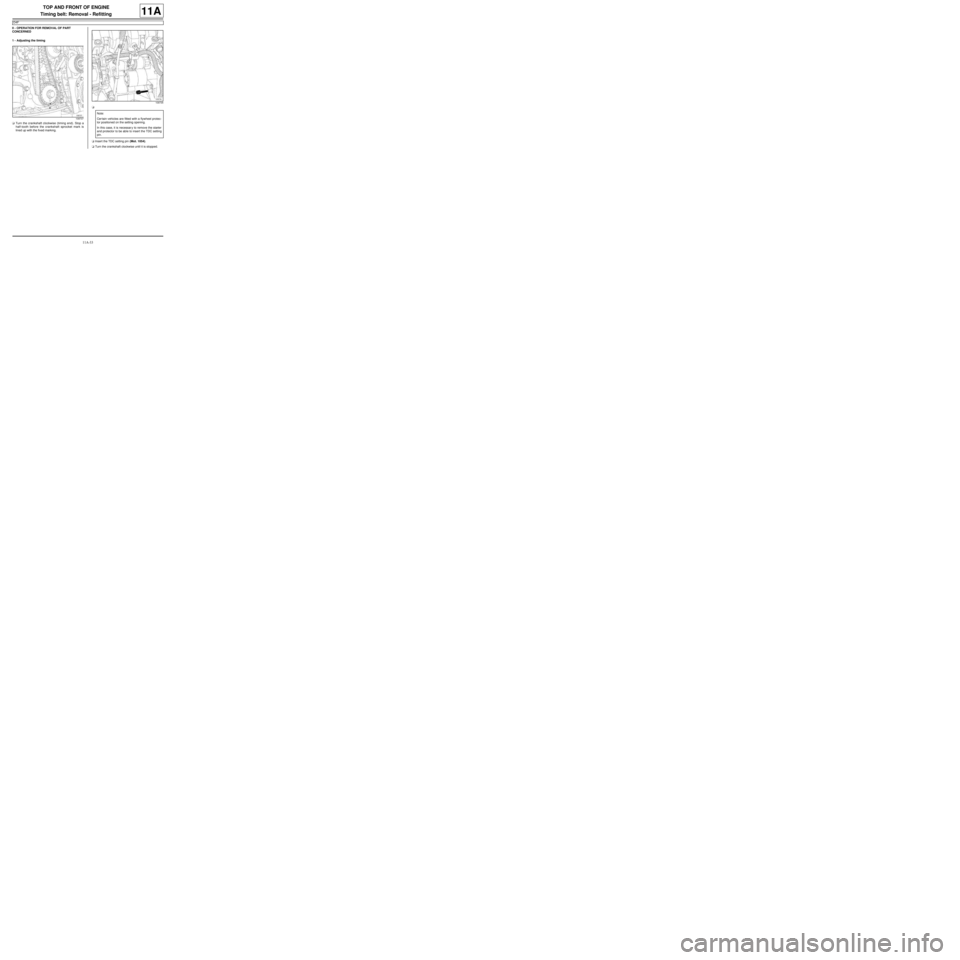
1 - Adjusting the timing
aTurn the crankshaft clockwise (timing end). Stop a
half-tooth before the crankshaft sprocket mark is
lined up with the fixed marking.a
aInsert the TDC setting pin (Mot. 1054).
aTurn the crankshaft clockwise until it is stopped.
109737
109735
Note:
Cer tain vehicles are fitted with a flywheel protec-
tor positioned on the setting opening.
In this case, it is necessar y to remove the starter
and protector to be able to insert the TDC setting
pin.
Page 152 of 652
11A-35
TOP AND FRONT OF ENGINE
Timing belt: Removal - Refitting
D4F
11A
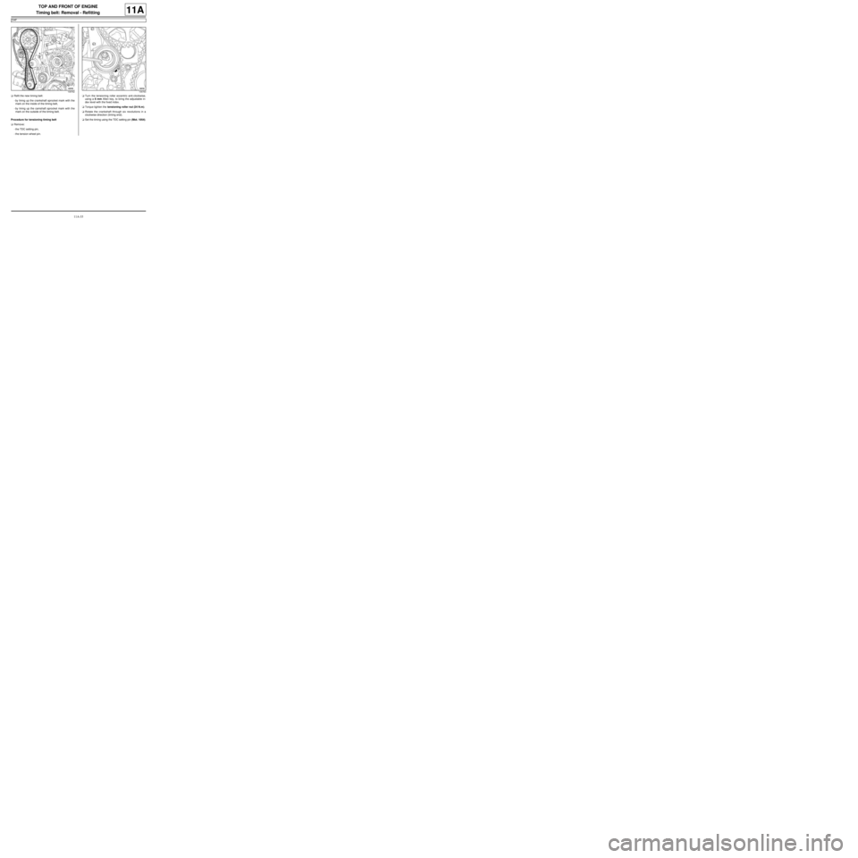
aRefit the new timing belt:
-by lining up the crankshaft sprocket mark with the
mark on the inside of the timing belt,
-by lining up the camshaft sprocket mark with the
mark on the outside of the timing belt.
Procedure for tensioning timing belt
aRemove:
-the TDC setting pin,
-the tension wheel pin.aTurn the tensioning roller eccentric anti-clockwise,
using a 6 mm Allen key, to bring the adjustable in-
dex level with the fixed index.
aTorque tighten the tensioning roller nut (24 N.m).
aRotate the crankshaft through six revolutions in a
clockwise direction (timing end).
aSet the timing using the TDC setting pin (Mot. 1054).
109762109763
Page 153 of 652
11A-36
TOP AND FRONT OF ENGINE
Timing belt: Removal - Refitting
D4F
11A
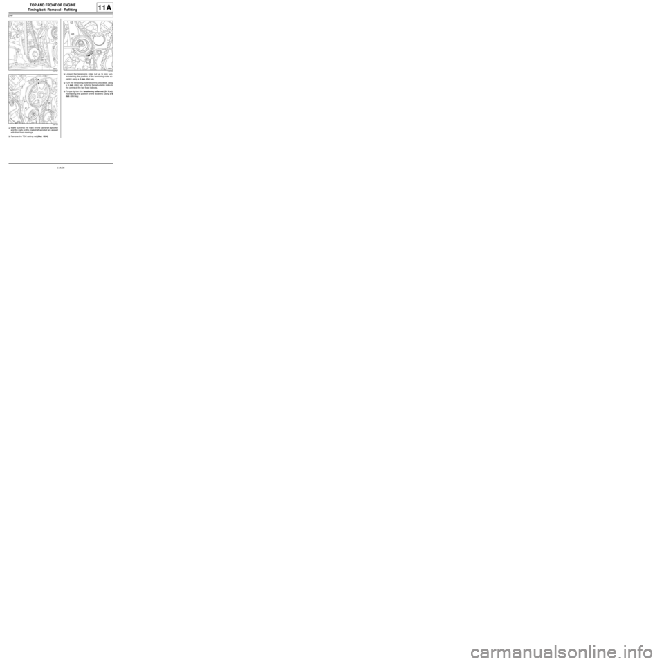
aMake sure that the mark on the camshaft sprocket
and the mark on the crankshaft sprocket are aligned
with their fixed markings.
aRemove the TDC setting rod (Mot. 1054).aLoosen the tensioning roller nut up to one turn,
maintaining the position of the tensioning roller ec-
centric using a 6 mm Allen key.
aTurn the tensioning roller eccentric clockwise, using
a 6 mm Allen key, to bring the adjustable index to
the centre of the two fixed indexes.
aTorque tighten the tensioning roller nut (24 N.m),
maintaining the position of the eccentric using a 6
mm Allen key.
109737
109738109764
Page 168 of 652
11A-51
TOP AND FRONT OF ENGINE
Timing belt: Removal - Refitting
K9K
11A
aRemove:
-the (Mot. 1489),
-the (Mot. 1430).
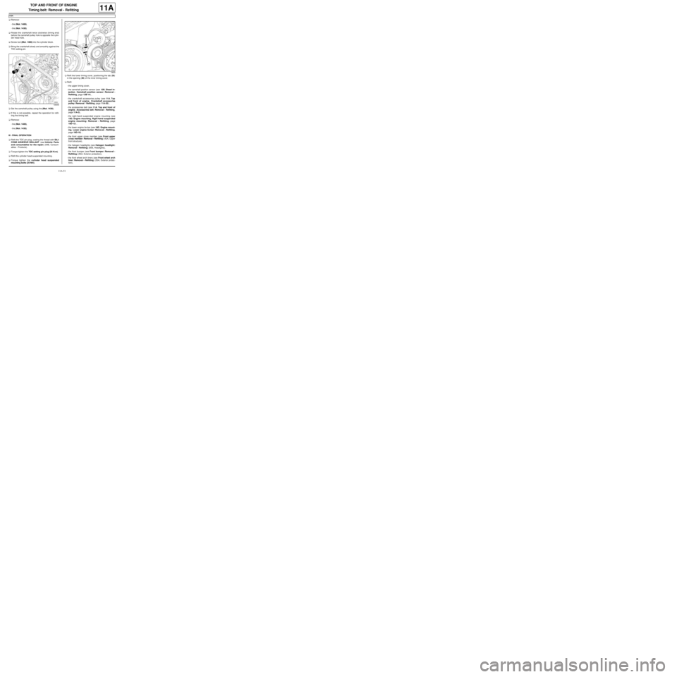
aRotate the crankshaft twice clockwise (timing end)
before the camshaft pulley hole is opposite the cylin-
der head hole.
aScrew tool (Mot. 1489) into the cylinder block.
aBring the crankshaft slowly and smoothly against the
TDC setting pin.
aSet the camshaft pulley using the (Mot. 1430).
aIf this is not possible, repeat the operation for refit-
ting the timing belt.
aRemove:
-the (Mot. 1489),
-the (Mot. 1430).
III - FINAL OPERATION
aRefit the TDC pin plug, coating the thread with SILI-
CONE ADHESIVE SEALANT (see Vehicle: Parts
and consumables for the repair) (04B, Consum-
ables - Products).
aTorque tighten the TDC setting pin plug (25 N.m).
aRefit the cylinder head suspended mounting .
aTorque tighten the cylinder head suspended
mounting bolts (25 Nm).aRefit the lower timing cover, positioning the tab (35)
in the opening (36) of the inner timing cover.
aRefit:
-the upper timing cover,
-the camshaft position sensor (see 13B, Diesel in-
jection, Camshaft position sensor: Removal -
Refitting, page 13B-14) ,
-the crankshaft accessories pulley (see 11A, Top
and front of engine, Crankshaft accessories
pulley: Removal - Refitting, page 11A-20) ,
-the accessories belt (see 11A, Top and front of
engine, Accessories belt: Removal - Refitting,
page 11A-3) ,
-the right-hand suspended engine mounting (see
19D, Engine mounting, Right-hand suspended
engine mounting: Removal - Refitting, page
19D-13) ,
-the lower engine tie-bar (see 19D, Engine mount-
ing, Lower engine tie-bar: Removal - Refitting,
page 19D-18) ,
-the front upper cross member (see Front upper
cross member: Removal - Refitting) (42A, Upper
front structure),
-the halogen headlights (see Halogen headlight:
Removal - Refitting) (80B, Headlights),
-the front bumper (see Front bumper: Removal -
Refitting) (55A, Exterior protection),
-the front wheel arch liners (see Front wheel arch
liner: Removal - Refitting) (55A, Exterior protec-
tion),
109049
19659
Page 172 of 652

11A-55
TOP AND FRONT OF ENGINE
Timing belt: Removal - Refitting
K4M
11A
aRemove the lifting eye (8) .
aPierce the centre of the plugs (9) at the camshaft
ends with a screwdriver.
aRemove:
-the plugs from the camshaft ends with a screwdriv-
er,
-the TDC setting pin plug (10) .aPosition the camshaft grooves (11) almost horizon-
tally and offset towards the bottom turning the crank-
shaft in the operating direction (clockwise at timing
end).
aScrew in the TDC setting pin (Mot. 1489) (12) .
aTurn the crankshaft in its operating direction (clock-
wise at timing end), until the crankshaft presses
against the TDC setting pin (Mot. 1489).
1449114491-1
14489
Page 179 of 652
11A-62
TOP AND FRONT OF ENGINE
Timing belt: Removal - Refitting
K4M
11A
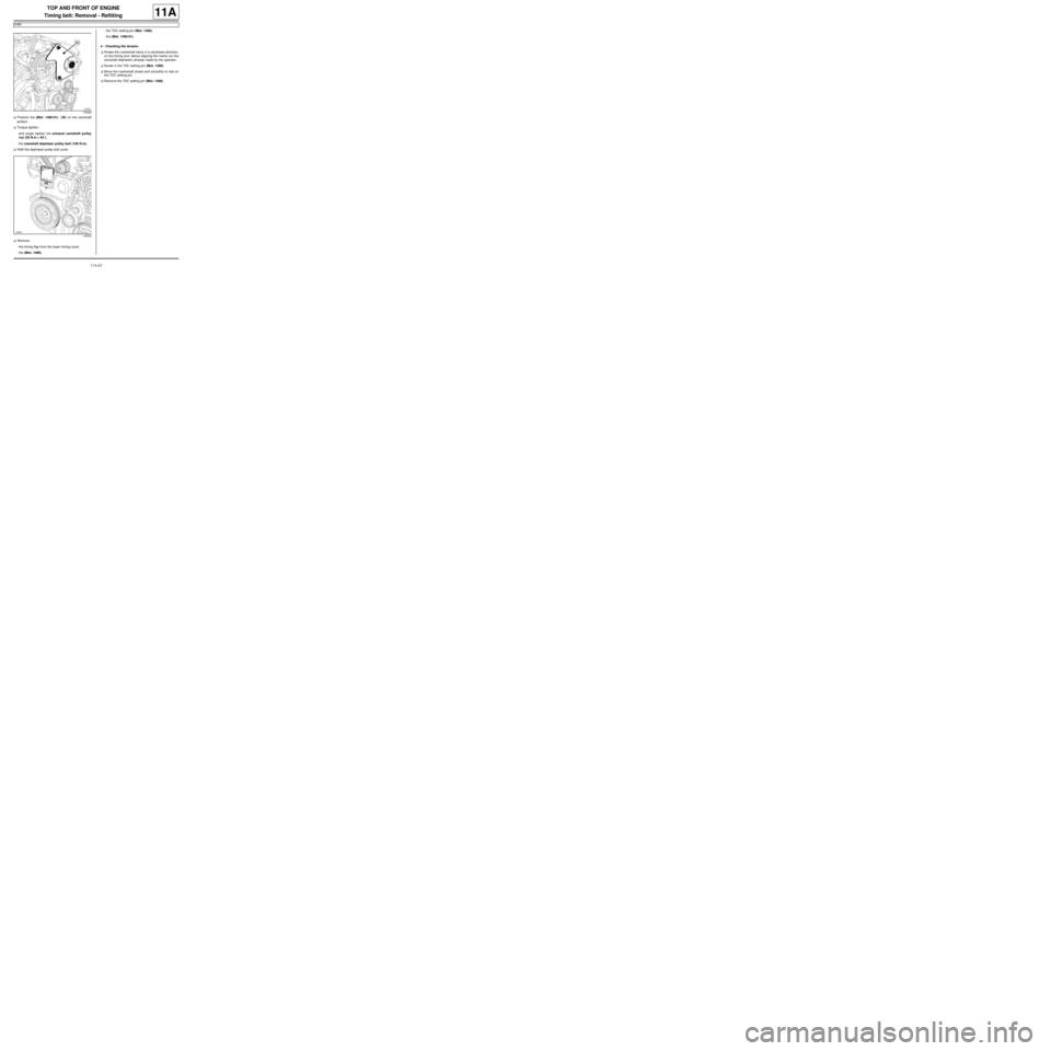
aPosition the (Mot. 1490-01) (30) on the camshaft
pulleys.
aTorque tighten:
-and angle tighten the exhaust camshaft pulley
nut (30 N.m + 84˚),
-the camshaft dephaser pulley bolt (100 N.m).
aRefit the dephaser pulley bolt cover.
aRemove:
-the timing flap from the lower timing cover,
-the (Mot. 1496),-the TDC setting pin (Mot. 1489),
-the (Mot. 1490-01).
4 - Checking the tension
aRotate the crankshaft twice in a clockwise direction,
on the timing end, before aligning the marks (on the
camshaft dephaser) already made by the operator.
aScrew in the TDC setting pin (Mot. 1489).
aMove the crankshaft slowly and smoothly to rest on
the TDC setting pin.
aRemove the TDC setting pin (Mot. 1489).
103265
109052