warning RENAULT TWINGO RS 2009 2.G Panelwork Owner's Manual
[x] Cancel search | Manufacturer: RENAULT, Model Year: 2009, Model line: TWINGO RS, Model: RENAULT TWINGO RS 2009 2.GPages: 209
Page 84 of 209
41C-9
SIDE LOWER STRUCTURE
Sill panel closure panel: General description
41C
If there are other issues regarding access to mating fa-
ces, the various options are described in the basic ins-
tructions for structural bodywork repair (see MR 400). WARNING
If the mating faces of the parts to be welded are not
accessible, make EGW plug welds to replace the
original resistance welds (see MR 400).
Page 85 of 209
41C-10
SIDE LOWER STRUCTURE
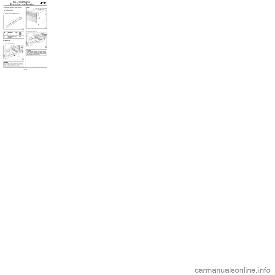
Sill panel closure panel: Description
41C
The options for replacing this part are as follows:
-front partial replacement,
-rear partial replacement.
I - COMPOSITION OF THE SPARE PART
II - PART FITTED
1 - Partial front replacementSection A
2 - Partial rear replacement
121057
No. Description Type Thic-
kness
(mm)
(1) Sill closure panel
componentHLE 0.95
120967
WARNING
For the partial replacement of parts constituting a
single structural component, it is essential to stag-
ger the welds of each of the components.
120965
120966
WARNING
If the spot welds cannot be made as they were ori-
ginally using an electrical spot welding machine,
they should be replaced with plug welds after holes
have been drilled in the first panel.
Page 88 of 209
41C-13
SIDE LOWER STRUCTURE
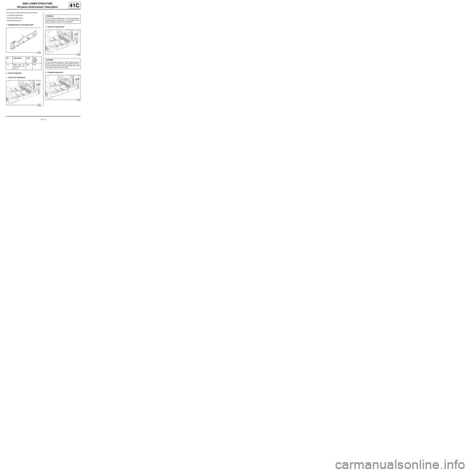
Sill panel reinforcement: Description
41C
The options for replacing this part are as follows:
-front partial replacement,
-Rear partial replacement
-complete replacement.
I - COMPOSITION OF THE SPARE PART
II - PART IN POSITION
1 - Partial front replacement2 - Partial rear replacement
3 - Complete replacement
121051
No. Description Type Thic-
kness
(mm)
(1) Body side clo-
sure panel com-
ponentHLE 0.85
120969
WARNING
For the partial replacement of parts constituting a
single structural component, it is essential to stag-
ger the welds of each of the components.
120968
WARNING
If the spot welds cannot be made as they were ori-
ginally using an electrical spot welding machine,
they should be replaced with plug welds after holes
have been drilled in the first panel.
120970
Page 90 of 209
41C-15
SIDE LOWER STRUCTURE
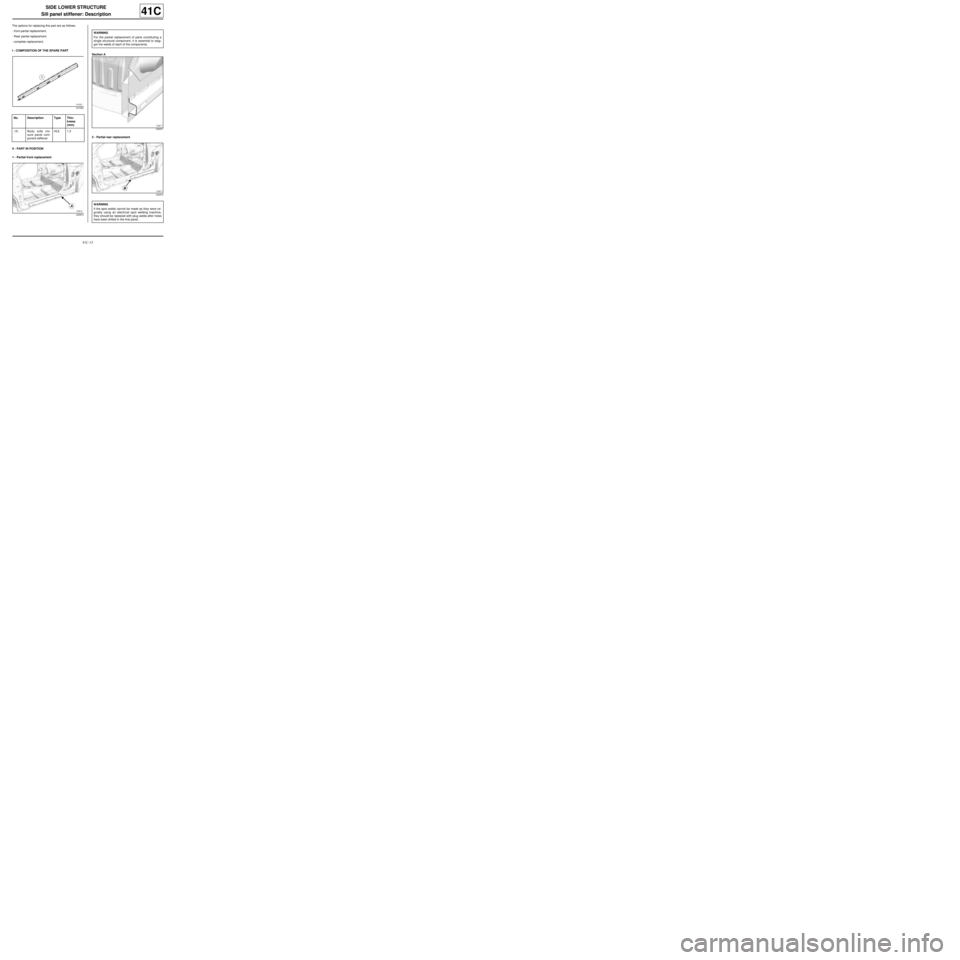
Sill panel stiffener: Description
41C
The options for replacing this part are as follows:
-front partial replacement,
-Rear partial replacement
-complete replacement.
I - COMPOSITION OF THE SPARE PART
II - PART IN POSITION
1 - Partial front replacementSection A
2 - Partial rear replacement
121052
No. Description Type Thic-
kness
(mm)
(1) Body side clo-
sure panel com-
ponent stiffenerHLE 1.2
120974
WARNING
For the partial replacement of parts constituting a
single structural component, it is essential to stag-
ger the welds of each of the components.
120971
120973
WARNING
If the spot welds cannot be made as they were ori-
ginally using an electrical spot welding machine,
they should be replaced with plug welds after holes
have been drilled in the first panel.
Page 93 of 209
41D-2
REAR LOWER STRUCTURE
Rear floor: Description
41D
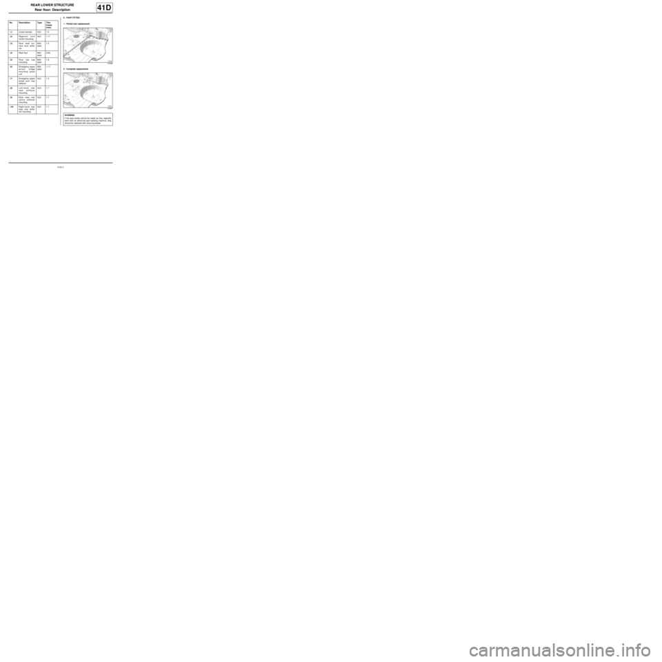
II - PART FITTED
1 - Partial rear replacement
2 - Complete replacement No. Description Type Thic-
kness
(mm)
(1) Cross member HLE 1.5
(2) Reservoir front
centre mountingHLE 1.17
(3) Rear seat run-
ners front stiffe-
nerMild
steel1.2
(4) Rear floor Mild
steel0.65
(5) Rear tow eye
mountingMild
steel1.8
(6) Emergency spare
wheel bridge
mounting piece
unitMild
steel1.17
(7) Emergency spare
wheel arch rear
stiffenerHLE 1.5
(8) Left-hand rear
seat stiffener
mountingHLE 1.7
(9) Rear seat rear
centre stiffener
mountingHLE 1.7
(10) Right-hand rear
seat rear stiffe-
ner mountingHLE 1.7
120988
120987
WARNING
If the spot welds cannot be made as they originally
were with an electrical spot welding machine, they
should be replaced with securing beads.
Page 97 of 209
41D-6
REAR LOWER STRUCTURE
Rear side member assembly: Description
C44
41D
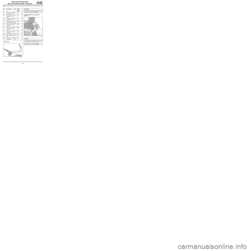
II - PART FITTEDIII - POSITIONING OF LOCAL ELECTRICAL
EARTHS No. Description Type Thic-
kness
(mm)
(1) Rear side mem-
ber reinforcementHLE1.5
(2) Connection com-
ponent reinforce-
mentHLE1.5
(3) Rear spring cup
reinforcementHLE1.5
(4) Side cross mem-
ber reinforcementMild
steel0.95
(5) Lower section of
rear side cross
memberHLE0.95
(6) Upper section of
rear side cross
memberHLE0.95
(7) Rear axle bea-
ring spacerHLE2.5
(8) Rear spring cup HLE1.5
(9) Rear side mem-
berHLE1.5
(10) Exhaust moun-
ting stiffenerMild
steel2
120977
IMPORTANT
If the mating faces of the parts to be welded are not
accessible, make EGW plug welds to replace the
original resistance welds (see MR 400).
121249
WARNING
To avoid damaging the vehicles electric and electro-
nic components, the earths of any wiring harness
near the weld area must be disconnected.
Position the earth of the welding machine as closely
as possible to the weld area (see MR 400).
Page 98 of 209
41D-7
REAR LOWER STRUCTURE
Rear side member: General description
41D
I - DESIGN OF THE STRUCTURAL COMPONENT
This is a basic part; it simply fulfils the function of a rear
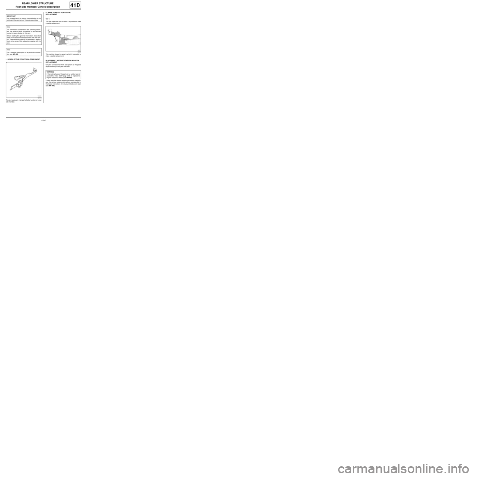
side member.II - AREA TO BE CUT FOR PARTIAL
REPLACEMENT
Cut 1:
This line marks the area in which it is possible to make
a partial replacement.
This marking shows the area in which it is possible to
make a partial replacement.
III - ASSEMBLY INSTRUCTIONS FOR A PARTIAL
REPLACEMENT
Only the connections which are specific to the partial
replacement by cutting are indicated.
If there are other issues regarding access to mating fa-
ces, the various replacement options are described in
the basic instructions for structural bodywork repair
(see MR 400). IMPORTANT
Use a repair bench to ensure the positioning of the
points and the geometr y of the axle assemblies.
Note:
The information contained in the following descri-
bes the general repair procedure for all vehicles
having the same design for this part.
Before reading this general information, check that
there are no special notes associated with this vehi-
cle. These special notes will be specified if applica-
ble in other parts of this subsection dealing with the
par t.
Note:
For a detailed description of a particular connec-
tion, see MR 400.
121042
120979
WARNING
If the mating faces of the parts to be welded are not
accessible, make EGW plug welds to replace the
original resistance welds (see MR 400).
Page 99 of 209
41D-8
REAR LOWER STRUCTURE
Rear side member: Description
41D
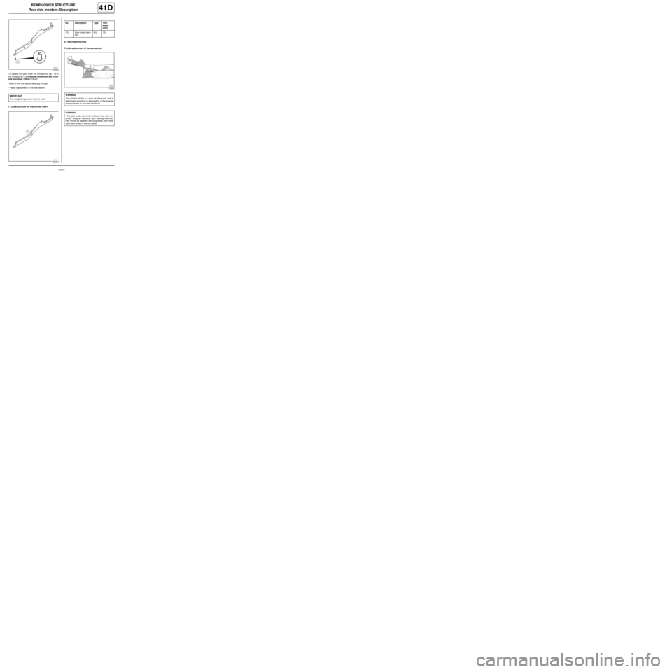
To replace this part, order the crimped nut (A) . To fit
the crimped nut ( (see Bolted connection with crim-
ped mounting: Fitting) Fitting).
There is only one way of replacing this part:
-Partial replacement of the rear section.
I - COMPOSITION OF THE SPARE PARTII - PART IN POSITION
Partial replacement of the rear section
121043
IMPORTANT
The straightening bench must be used.
121181
No. Description Type Thic-
kness
(mm)
(1) Rear side mem-
berHLE 1.5
120979
WARNING
The position of this cut must be obser ved, and is
determined according to the position of the internal
reinforcements or acoustic inserts cut.
WARNING
If the spot welds cannot be made as they were ori-
ginally using an electrical spot welding machine,
they should be replaced with plug welds after holes
have been drilled in the first panel.
Page 101 of 209
41D-10
REAR LOWER STRUCTURE
Rear floor front cross member: General description
41D
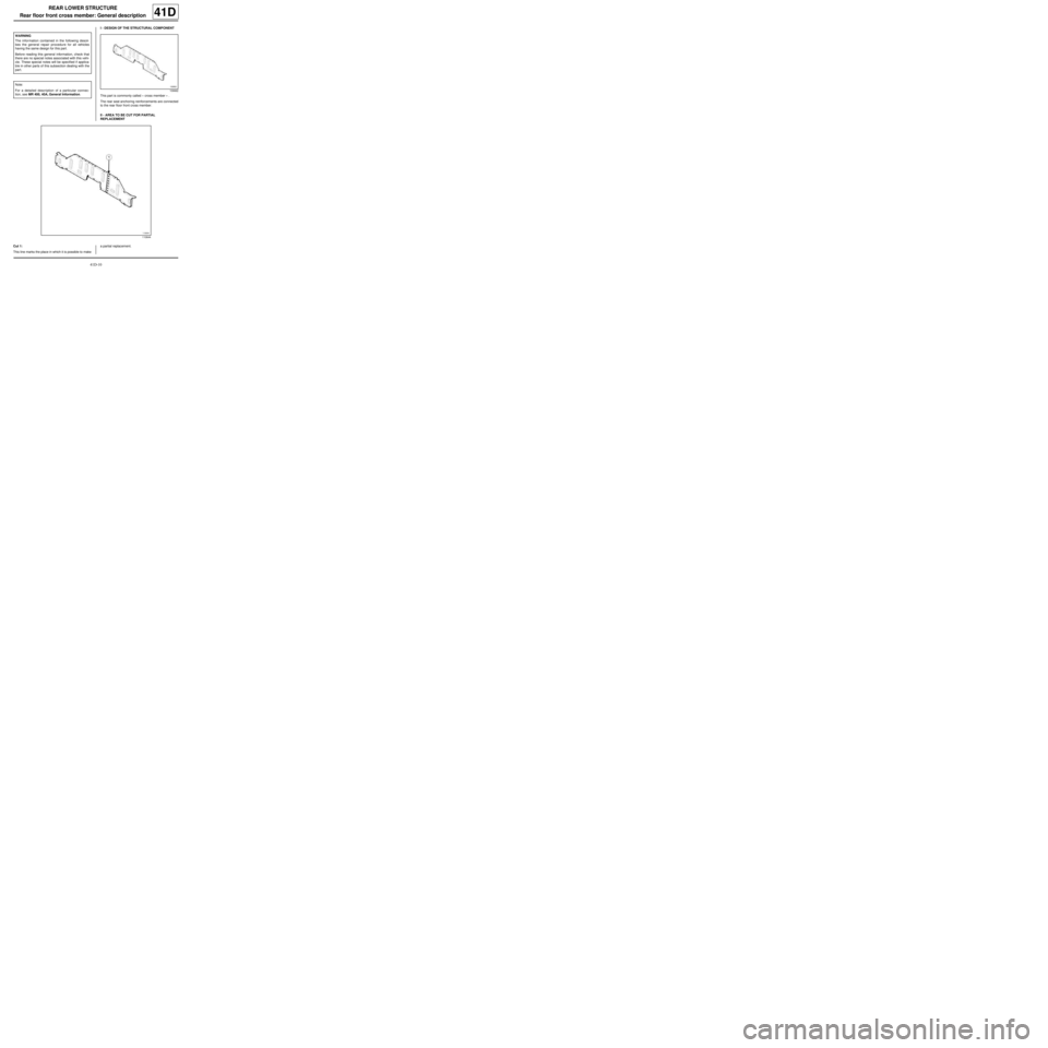
I - DESIGN OF THE STRUCTURAL COMPONENT
This part is commonly called « cross member » .
The rear seat anchoring reinforcements are connected
to the rear floor front cross member.
II - AREA TO BE CUT FOR PARTIAL
REPLACEMENT
Cut 1:
This line marks the place in which it is possible to makea partial replacement. WARNING
The information contained in the following descri-
bes the general repair procedure for all vehicles
having the same design for this part.
Before reading this general information, check that
there are no special notes associated with this vehi-
cle. These special notes will be specified if applica-
ble in other parts of this subsection dealing with the
par t.
Note:
For a detailed description of a particular connec-
tion, see MR 400, 40A, General Information.
109662
110644
Page 102 of 209
41D-11
REAR LOWER STRUCTURE
Rear floor front cross member: General description
41D
This operation allows you to access the inside of the
hollow section of the structural element to straighten it.
III - ASSEMBLY INSTRUCTIONS FOR A PARTIAL
REPLACEMENT
Only the connections which are specific to the partial
replacement by cutting are indicated.
If there are other issues regarding access to mating fa-
ces, the various replacement options are described in
the basic instructions for structural bodywork repair
(see MR 400, 40A, General Information).
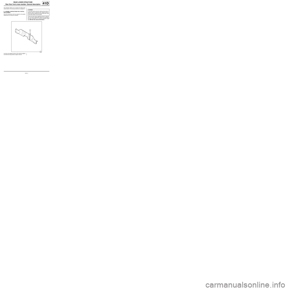
Line (2) on the diagram shows a joint made by joggling
connected with plug welds at regular intervals.WARNING
If the spot welds cannot be made as they were ori-
ginally using an electrical spot welding machine,
they should be replaced with plug welds after holes
have been drilled in the first panel.
110644