brake light RENAULT TWINGO RS 2009 2.G Sequential Transmission User Guide
[x] Cancel search | Manufacturer: RENAULT, Model Year: 2009, Model line: TWINGO RS, Model: RENAULT TWINGO RS 2009 2.GPages: 138
Page 79 of 138
21B-79
MR-413-X44-21B000$590.mif
V2
21B
SEQUENTIAL GEARBOX
Fault finding - Status summary table
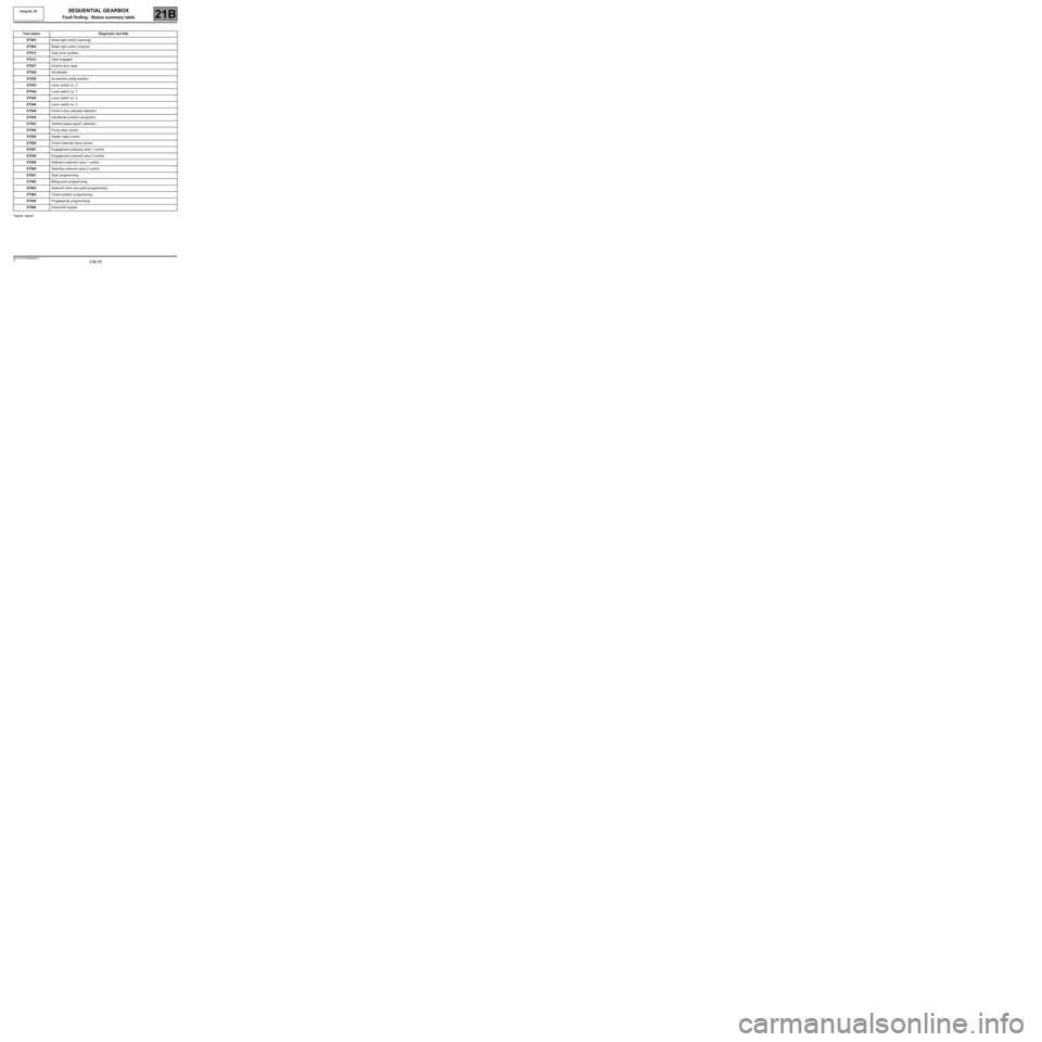
*signal: signalTool status Diagnostic tool title
ET003Brake light switch (opening)
ET004Brake light switch (closure)
ET012Gear lever position
ET013Gear engaged
ET027Driver's door open
ET028Handbrake
ET030Accelerator pedal position
ET043Lever switch no. 0
ET044Lever switch no. 1
ET045Lever switch no. 2
ET046Lever switch no. 3
ET048Driver's door statuses detection
ET049Handbrake position recognition
ET053Vehicle speed signal* detection
ET054Pump relay control
ET055Starter relay control
ET056Clutch solenoid valve control
ET057Engagement solenoid valve 1 control
ET058Engagement solenoid valve 2 control
ET059Selection solenoid valve 1 control
ET060Selection solenoid valve 2 control
ET061Gear programming
ET062Biting point programming
ET063Solenoid valve zero point programming
ET064Clutch position programming
ET065Progressivity programming
ET086Downshift request
Vdiag No: 04
MR-413-X44-21B000$590.mif
Page 80 of 138
21B-80
MR-413-X44-21B000$649.mif
V2
21B
SEQUENTIAL GEARBOX
Fault finding - Interpretation of statuses
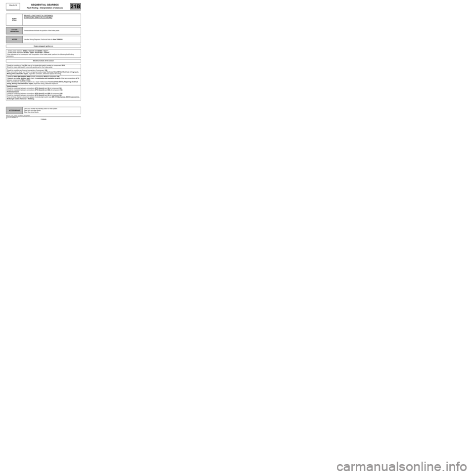
ET003
ET004
BRAKE LIGHT SWITCH (OPENING)
STOP LIGHT SWITCH (CLOSURE)
STATUS
DEFINITIONThese statuses indicate the position of the brake pedal.
NOTESUse the Wiring Diagrams Technical Note for New TWINGO.
Engine stopped, ignition on
–Brake pedal released: ET003: "Closed" and ET004: "Open".
–Brake pedal depressed: ET003: "Open" and ET004: ''Closed".
If the statuses do not correspond with the position of the brake pedal, perform the following fault finding
procedure.
Electrical check of the sensor
Check the condition of the 15 A fuse of the brake light switch located on component 1016.
Check the brake light switch is correctly positioned on the brake pedal.
Check the condition and correct connection of component 160.
If the connector is faulty and there is a repair procedure (see Technical Note 6015A, Electrical wiring repair,
Wiring: Precautions for repair), repair the connector, otherwise replace the wiring.
Check for the + after ignition feed on both connections AP10 of component 160.
If there is no + after ignition feed, check the continuity and insulation to earth of the two connections AP10
between components 160 and 1016.
If the connection(s) are faulty and there is a repair method (see Technical Note 6015A, Repairing electrical
wiring, W iring: Precautions for repair), repair the wiring, otherwise replace it.
Pedal released:
Check the continuity between connections AP10 (track 4) and 5A of component 160.
Check the insulation between connections AP10 (track 2) and 65A of component 160.
Pedal depressed:
Check the continuity between connections AP10 (track 2) and 65A of component 160.
Check the insulation between connections AP10 (track 4) and 5A of component 160.
If one of these checks is incorrect, replace the brake light switch (see MR 411 Mechanical, 83D Cruise control,
Brake light switch: Removal - Refitting).
AFTER REPAIRCarry out another fault finding check on the system.
Deal with any other faults.
Clear the stored faults.
BVRJH1_V04_ET003 / BVRJH1_V04_ET004
MR-413-X44-21B000$649.mif
Vdiag No: 04
Page 125 of 138
21B -125
MR-413-X44-21B000$885.mif
V2
Vdiag No: 04SEQUENTIAL GEARBOX
Fault finding - Interpretation of commands21B
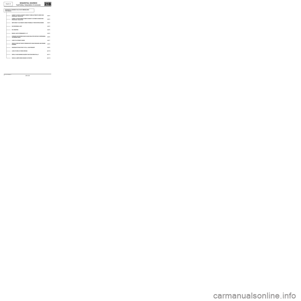
SEQUENTIAL GEARBOX FAULTS NOT IMMOBILISING
THE VEHICLE
CANNOT ACCESS AUTOMATIC MODE IF SEMI-AUTOMATIC MODE WAS
PREVIOUSLY SELECTEDALP 4
CANNOT ACCESS SEMIAUTOMATIC MODE IF AUTOMATIC MODE WAS
PREVIOUSLY SELECTEDALP 4
SWITCHING TO AUTOMATIC MODE POSSIBLE IF RESTARTING ENGINE ALP 4
NO REVERSING LIGHT ALP 5
NO CREEPING ALP 6
BRAKE LIGHTS PERMANENTLY LIT ALP 6
FORWARD OR REVERSE GEAR CAN BE SELECTED WITHOUT DEPRESSING
THE BRAKE PEDALALP 6
LOSS OF AUTOMATIC MODE ALP 7
VEHICLE DOES NOT MOVE FORWARD WITH GEAR ENGAGED AND ENGINE
RUNNINGALP 8
INADEQUATE REACTION TO FULL LOAD REQUEST ALP 9
LOSS OF DISPLAY WHEN DRIVING ALP 10
DISPLAY AND WARNING BUZZER FUNCTION ERRATICALLY ALP 11
VEHICLE JUMPS WHEN ENGINE IS STARTED ALP 12
Page 127 of 138
21B -127
MR-413-X44-21B000$944.mif
V2
SEQUENTIAL GEARBOX
Diagnostic - Fault finding chart
Vdiag No: 04
21B
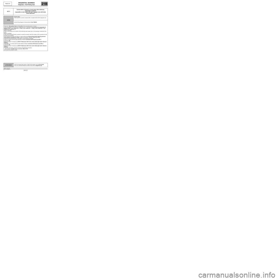
ALP 2Cannot select a forward or reverse gear when stationary
Impossible to select N
Impossible to start engine with gear engaged, even with brake
pedal depressed
NOTESSpecial notes:
Only consult this customer complaint after a complete check with the diagnostic tool.
Use the Wiring Diagrams Technical Note for New TWINGO.
Check the + after ignition feeds and the earths of the sequential gearbox computer.
Check the condition of the gear lever contacts and that it is operating correctly (consult the interpretation of
statuses ET043 "Lever contact No. 0", ET044 "Lever contact No. 1", ET045 "Lever contact No. 2" and
ET046 Lever contact No. 3").
Repair if necessary.
Check for the presence and condition of the brake light switch supply fuse on the passenger compartment fuse
board.
Repair if necessary.
Check that the brake light switch connector is correctly connected, check the condition of the connections as well
as those of the computer.
If the connectors are faulty and if there is a repair method (see Technical Note 6015A, Repairing electrical
wiring, W iring: Precautions for repair), repair the connectors; otherwise, replace the wiring.
Check that the brake light switch on the pedal is correctly fitted and adjusted.
Check for continuity, with the pedal depressed, between connections AP10 (track 2) and 65A of
component 160.
Replace the switch if necessary (see MR 411 Mechanical, 83D Cruise control, Brake light switch: Removal -
Refitting).
Check there is no continuity with the pedal released, between connections AP10 (track 2) and 65A of
component 160.
Replace the switch if necessary (see MR 411 Mechanical, 83D Cruise control, Brake light switch: Removal -
Refitting).
If the fault is still present, check the continuity of the following connection:
●Connection code 65A between components 160 and 119.
Also ensure the insulation to earth.
AFTER REPAIRClear the computer fault memory. Switch off the ignition and wait 20 seconds.
Carry out a road test followed by another check with the diagnostic tool.
BVRJH1_V04_ALP2
Page 132 of 138
21B -132
MR-413-X44-21B000$944.mif
V2
SEQUENTIAL GEARBOX
Diagnostic - Fault finding chart
Vdiag No: 04
21B
ALP 6No creeping
Brake lights permanently lit
Forward or reverse gear can be selected without depressing the
brake pedal
NOTESSpecial notes:
Only consult this customer complaint after a complete check with the diagnostic tool.
In a case where there is no creeping, if the customer has heard the buzzer whilst
driving, it is normal for creeping to be prohibited (clutch overheating). Leave the clutch
to cool down and then check if there is any creep. Apply the following procedure if the
fault persists.
Use the Wiring Diagrams Technical Note for New TWINGO.
Check for the presence, condition and correct positioning of the brake light fuse in the passenger
compartment fuse box.
Check the connection and condition of the connectors of components 160, 156 and 119.
If the connectors are faulty and if there is a repair method (see Technical Note 6015A, Repairing electrical
wiring, W iring: Precautions for repair), repair the connectors; otherwise, replace the wiring.
Check the fitting and adjustment of component 160 on the pedals.
Pedal depressed:
Check the continuity between connections AP10 (track 2) and 65A of component 160.
Check the insulation between connections AP10 (track 4) and 5A of component 160.
If the checks are incorrect, replace the switch (see MR 411 Mechanical systems, 83D Cruise control, Brake
light switch: Removal - Refitting).
Pedal released:
Check the insulation between connections AP10 (track 2) and 65A of component 160.
Check the continuity between connections AP10 (track 4) and 5A of component 160.
If the checks are incorrect, replace the switch (see MR 411 Mechanical systems, 83D Cruise control, Brake
light switch: Removal - Refitting).
Check the continuity and insulation from earth of the following connection:
●Connection code 65A,
between components 160 and 119.
If the connection is faulty and there is a repair procedure (see Technical Note 6015A, Electrical wiring repair,
Wiring: Precautions for repair), repair the wiring, otherwise replace it.
AFTER REPAIRClear the computer fault memory. Switch off the ignition and wait 20 seconds.
Carry out a road test followed by another check with the diagnostic tool.
BVRJH1_V04_ALP6