brake light RENAULT TWINGO RS 2009 2.G Sequential Transmission Workshop Manual
[x] Cancel search | Manufacturer: RENAULT, Model Year: 2009, Model line: TWINGO RS, Model: RENAULT TWINGO RS 2009 2.GPages: 138
Page 9 of 138
21B-9
MR-413-X44-21B000$177.mif
V2
Vdiag No: 04SEQUENTIAL GEARBOX
Fault finding - System operation21B
Description of gear lever positions (continued):
–"+": moving the gear lever towards this position enables the driver to shift up,
–“-”: moving the gear lever towards this position will enable the driver to shift down.
Description of the display:
This display is specifically for the sequential gearbox. It displays 4 types of information for the driver:
–displays the gear selected: 1, 2, 3, 4, 5, N or R,
–the pictogram displaying AUTO mode: this pictogram lights up when AUTO mode is selected,
–the “depress brake pedal” symbol: this symbol lights up when a driver action requires the brake pedal to be
depressed if the driver is not depressing the brake pedal. This symbol only lights up when there is an error (driver
actions without depressing the brake pedal = symbol lighting up),
–the sequential gearbox fault warning light: this lights up when the sequential gearbox computer detects a fault on
the sequential gearbox system.
General information about the operation:
Operation in MANUAL mode:
Manual mode allows the driver to select gears by moving the gear lever. However, in manual mode, the driver is not
completely free to do what he/she likes. This is why this mode is also called semiautomatic mode because the driver
is still assisted by the sequential gearbox computer in the following instances:
–when driving, shifting the lever towards the “+” position may result in underspeed. As a result, the sequential
gearbox computer forbids the driver's request,
–when driving, shifting the lever towards the “-” position may result in engine overspeed. As a result, the sequential
gearbox computer forbids the driver's request,
–when driving, as the overspeed threshold is approached, the computer automatically selects a higher gear,
–when driving, as the underspeed threshold is approached, the computer automatically selects a lower gear,
–when driving, if the vehicle speed reduces too quickly (brakes applied), the sequential gearbox computer can
order a downshift. Reminder:
Creep is only possible in first or reverse gears; it makes parking manoeuvres easier: if the brake pedal or
the handbrake is released, the vehicle moves forward by itself, without the driver having to accelerate.
Creeping is not possible in second gear.
Page 12 of 138
21B-12
MR-413-X44-21B000$177.mif
V2
Vdiag No: 04SEQUENTIAL GEARBOX
Fault finding - System operation21B
Depress brake pedal symbol:
–The “depress brake” symbol lights up when there is:
–a request to change gear when stopped without the brake pedal applied,
–a request to start the engine with gear engaged without brake pedal applied,
–a request to select N when driving without brake pedal applied,
–a request to select AUTO, with the vehicle stationary, the engine running and 2
nd gear engaged.
–Depress brake pedal symbol goes out:
The symbol goes out if the driver depresses the brake pedal or after a delay.
In the event that the driver makes a request causing the gear requested to flash and the symbol to be displayed at
the same time, they will be synchronised and last for the same period of time.
Fault warning light:
This warning light comes on when a fault is detected by the sequential gearbox computer.Note:
If, while the symbol is lit, the driver depresses the brake pedal, the symbol will go out and the display will return to
its previous status (the lever request is not registered).
Page 22 of 138
21B-22
MR-413-X44-21B000$354.mif
V2
21B
SEQUENTIAL GEARBOX
Fault finding - Fault summary table
*RR: rearTool faultAssociated
DTCDiagnostic tool title
DF0020613 Computer
DF0390725 Engine speed signal
DF0430785 Gear change consistency
DF0465002 Idling setpoint multiplex signal
DF0480720 Vehicle speed signal
DF059C100 Injection connection → Automatic transmission (multiplex line signal)
DF062C073 Multiplex line fault
DF0650945 Pump relay circuit
DF0670820 Lever position switch circuit
DF0680805 Clutch position sensor circuit
DF0690904 Selection position sensor circuit
DF0700914 Engagement position sensor circuit
DF0710750 Clutch solenoid valve circuit
DF0720755 Engagement solenoid valve 1 circuit
DF0730760 Engagement solenoid valve 2 circuit
DF0740765 Selection solenoid valve 1 circuit
DF0750770 Selection solenoid valve 2 circuit
DF0760900 Clutch control
DF0770928 Gearbox servo control
DF0780944 Hydraulic servo control
DF0800560 Battery voltage
DF0820571 Brake lights switch circuit
DF1075000 Engine speed multiplex signal
DF1084073 Effective average torque multiplex signal
DF1145007 Pedal position multiplex signal
DF1155005 Torque multiplex signal
DF1174037 RR* wheel speed multiplex signal left
DF118403A RR* right-hand wheel speed multiplex signal
DF122C140 Passenger compartment computer connection
Vdiag No: 04
MR-413-X44-21B000$354.mif
Page 36 of 138
21B-36
MR-413-X44-21B000$413.mif
V2
SEQUENTIAL GEARBOX
Fault finding - Interpretation of faults
Vdiag No.: 04
21B
DF070
PRESENT
OR
STOREDENGAGEMENT POSITION SENSOR CIRCUIT
CC.0: Short circuit to earth
CO.1: Open circuit or short circuit to + 12 V
NOTESSpecial note:
Fault warning light comes on.
Starting is not permitted until the driver has depressed the brake pedal (enabling
neutral to be engaged).
Use the Wiring Diagrams Technical Note for New TWINGO.
Check the connection and condition of the connectors of components 1055 and 119.
If the connectors are faulty and if there is a repair method (see Technical Note 6015A, Repairing electrical
wiring, W iring: Precautions for repair), repair the connectors; otherwise, replace the wiring.
Check the continuity and insulation to earth and to + 12 V on the following connections:
●Connection code 5HN,
●Connection code 5HX,
●Connection code 5FA,
between components 1055 and 119.
If the connections are faulty, check the connection and condition of the intermediate connector R235 located on
the hydraulic unit.
If the connection(s) are faulty and there is a repair method (see Technical Note 6015A, Repairing electrical
wiring, W iring: Precautions for repair), repair the wiring, otherwise replace it.
Remove the engagement position sensor and check the wear of the cylinder-potentiometer mechanical
connection.
(see MR 411 Mechanical, 21B, Sequential gearbox, Engagement position sensor).
Repair if necessary.
If the checks are correct, replace the engagement position sensor (see MR 411 Mechanical, 21B, Sequential
gearbox, Engagement sensor: Removal - refitting).
If the fault is still present, contact the Techline.
AFTER REPAIRDeal with any faults displayed by the diagnostic tool.
Clear the computer memory.
Carry out a road test followed by another check with the diagnostic tool.
BVRJH1_V04_DF070
Page 38 of 138
21B-38
MR-413-X44-21B000$413.mif
V2
SEQUENTIAL GEARBOX
Fault finding - Interpretation of faults
Vdiag No.: 04
21B
DF072
PRESENT
OR
STOREDENGAGEMENT SOLENOID VALVE 1 CIRCUIT
CO: Open circuit
CC.0: Short circuit to earth
CC.1: Short circuit to + 12 volts
NOTESConditions for applying the fault finding procedure to stored faults:
A fault is declared present after engaging all gears, with the brake pedal depressed
and the engine stopped.
Special note:
–warning light comes on,
–automatic mode deactivated,
–certain gear changes are inhibited.
Use the Wiring Diagrams Technical Note for New TWINGO.
Check the connection and condition of the connectors of components 1051 and 119.
If the connectors are faulty and if there is a repair method (see Technical Note 6015A, Repairing electrical
wiring, W iring: Precautions for repair), repair the connectors; otherwise, replace the wiring.
Check the continuity and insulation to earth and to + 12 V on the following connections:
●Connection code 5FE,
between components 119 and 1051.
●Connection code N,
between component 1051 and chassis earth N.
If the connections are faulty, check the connection and condition of the intermediate connector R235 located on
the hydraulic unit.
If the connection(s) are faulty and there is a repair method (see Technical Note 6015A, Repairing electrical
wiring, W iring: Precautions for repair), repair the wiring, otherwise replace it.
Check that engagement solenoid valve 1 is operating correctly by carrying out a listening test using command
AC015 Engagement solenoid valves.
If the checks are correct, replace engagement solenoid valve 1 (see MR 411 Mechanical, 21B, Sequential
gearbox, Solenoid valves: Removal - Refitting).
If the fault is still present, contact the Techline.
AFTER REPAIRDeal with any faults displayed by the diagnostic tool.
Clear the computer memory.
Carry out a road test followed by another check with the diagnostic tool.
BVRJH1_V04_DF072
Page 39 of 138
21B-39
MR-413-X44-21B000$413.mif
V2
SEQUENTIAL GEARBOX
Fault finding - Interpretation of faults
Vdiag No.: 04
21B
DF073
PRESENT
OR
STOREDENGAGEMENT SOLENOID VALVE 2 CIRCUIT
CO: Open circuit
CC.0: Short circuit to earth
CC.1: Short circuit to + 12 V
NOTESConditions for applying the fault finding procedure to stored faults:
The fault is declared present after:
–engagement of any of the gears, with the brake pedal depressed and the engine
stopped.
Special note:
–warning light comes on,
–automatic mode deactivated,
–certain gear changes are inhibited.
Use the Wiring Diagrams Technical Note for New TWINGO.
Check the connection and condition of the connectors of components 1052 and 119.
If the connectors are faulty and if there is a repair method (see Technical Note 6015A, Repairing electrical
wiring, W iring: Precautions for repair), repair the connectors; otherwise, replace the wiring.
Check the continuity and insulation to earth and to + 12 V on the following connections:
●Connection code 5FF,
between components 119 and 1052.
●Connection code N,
between component 1052 and chassis earth N.
If the connections are faulty, check the connection and condition of the intermediate connector R235 located on
the hydraulic unit.
If the connection(s) are faulty and there is a repair method (see Technical Note 6015A, Repairing electrical
wiring, W iring: Precautions for repair), repair the wiring, otherwise replace it.
Check that engagement solenoid valve 2 is operating correctly by carrying out a listening test using command
AC015 Engagement solenoid valves.
If the checks are correct, replace engagement solenoid valve 2 (see MR 411 Mechanical, 21B, Sequential
gearbox, Solenoid valves: Removal - Refitting).
If the fault is still present, contact the Techline.
AFTER REPAIRDeal with any faults displayed by the diagnostic tool.
Clear the computer memory.
Carry out a road test followed by another check with the diagnostic tool.
BVRJH1_V04_DF073
Page 40 of 138
21B-40
MR-413-X44-21B000$413.mif
V2
SEQUENTIAL GEARBOX
Fault finding - Interpretation of faults
Vdiag No.: 04
21B
DF074
PRESENT
OR
STOREDSELECTION SOLENOID VALVE 1 CIRCUIT
CO.0: Open circuit or short circuit to earth
CC.1: Short circuit to + 12 V
NOTESConditions for applying the fault finding procedure to stored faults:
The fault is declared present after:
–engagement of any of the gears,
–the brake pedal is depressed,
–the engine is stopped.
Special notes:
–warning light comes on and automatic mode deactivated,
–if C0.0: only gear changes between 3-4 and reverse gear are authorised,
–if CC.1: only gear changes between 1 and 2 are authorised.
Use the Wiring Diagrams Technical Note for New TWINGO.
Check the connection and condition of the connectors of components 1053 and 119.
If the connectors are faulty and if there is a repair method (see Technical Note 6015A, Repairing electrical
wiring, W iring: Precautions for repair), repair the connectors; otherwise, replace the wiring.
Check the continuity and insulation to earth and to + 12 V on the following connections:
●Connection code 5FC,
between components 119 and 1053.
●Connection code N,
between component 1053 and chassis earth N.
If the connections are faulty, check the connection and condition of the intermediate connector R235 located on
the hydraulic unit.
If the connection(s) are faulty and there is a repair method (see Technical Note 6015A, Repairing electrical
wiring, W iring: Precautions for repair), repair the wiring, otherwise replace it.
Using the diagnostic tool, run command AC016 Selection solenoid valves and check that the selection is
made correctly by carrying out a listening test.
If the selection is not made correctly, replace selection solenoid valve 1 (see MR 411 Mechanical, 21B,
Sequential gearbox, Solenoid valves: Removal - Refitting).
If the fault is still present, contact the Techline.
AFTER REPAIRDeal with any faults displayed by the diagnostic tool.
Clear the computer memory.
Carry out a road test followed by another check with the diagnostic tool.
BVRJH1_V04_DF074
Page 41 of 138
21B-41
MR-413-X44-21B000$413.mif
V2
SEQUENTIAL GEARBOX
Fault finding - Interpretation of faults
Vdiag No.: 04
21B
DF075
PRESENT
OR
STOREDSELECTION SOLENOID VALVE 2 CIRCUIT
CO.0: Open circuit or short circuit to earth
CC.1: Short circuit to + 12 V
NOTESConditions for applying the fault finding procedure to stored faults:
The fault is declared present after:
–engagement of any of the gears,
–the brake pedal is depressed,
–the engine is stopped.
Special notes:
–warning light comes on and automatic mode deactivated,
–if C0.0: only gear changes 1, 2, 3, 4 and reverse are authorised,
–if CC.1: only selection of reverse gear is authorised.
Use the Wiring Diagrams Technical Note for New TWINGO.
Check the connection and condition of the connectors of components 1054 and 119.
If the connectors are faulty and if there is a repair method (see Technical Note 6015A, Repairing electrical
wiring, W iring: Precautions for repair), repair the connectors; otherwise, replace the wiring.
Check the continuity and insulation to earth and to + 12 V on the following connections:
●Connection code 5FD,
between components 119 and 1054.
●Connection code N,
between component 1054 and chassis earth N.
If the connections are faulty, check the connection and condition of the intermediate connector R235 located on
the hydraulic unit.
If the connection(s) are faulty and there is a repair method (see Technical Note 6015A, Repairing electrical
wiring, W iring: Precautions for repair), repair the wiring, otherwise replace it.
Using the diagnostic tool, run command AC016 Selection solenoid valves and check that the selection is made
correctly by carrying out a listening test.
If the selection is not made correctly, replace selection solenoid valve 2 (see MR 411 Mechanical, 21B,
Sequential gearbox, Solenoid valves: Removal - Refitting).
If the fault is still present, contact the Techline.
AFTER REPAIRDeal with any faults displayed by the diagnostic tool.
Clear the computer memory.
Carry out a road test followed by another check with the diagnostic tool.
BVRJH1_V04_DF075
Page 46 of 138
21B-46
MR-413-X44-21B000$413.mif
V2
SEQUENTIAL GEARBOX
Fault finding - Interpretation of faults
Vdiag No.: 04
21B
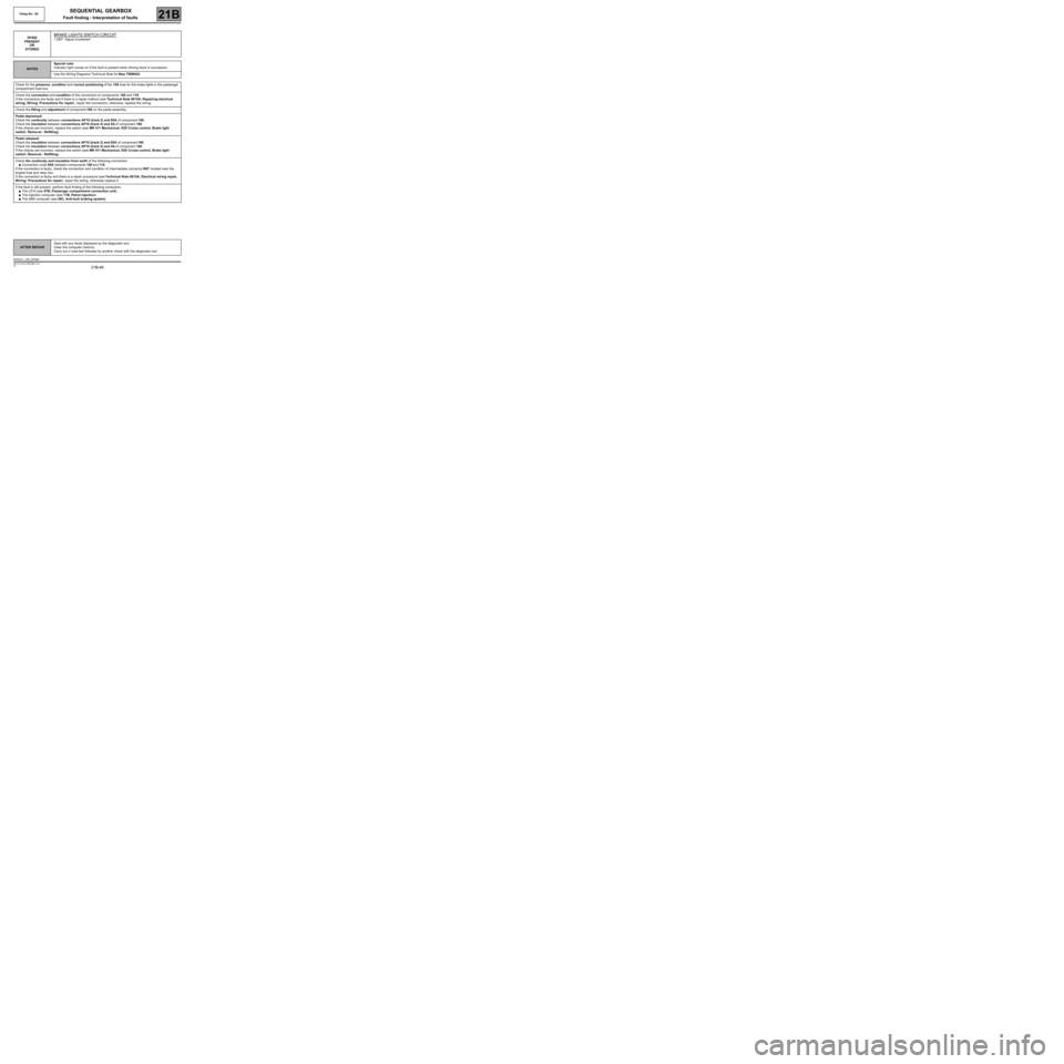
DF082
PRESENT
OR
STOREDBRAKE LIGHTS SWITCH CIRCUIT
1.DEF: Signal incoherent
NOTESSpecial note:
Indicator light comes on if the fault is present when driving twice in succession.
Use the Wiring Diagrams Technical Note for New TWINGO.
Check for the presence, condition and correct positioning of the 15A fuse for the brake lights in the passenger
compartment fuse box.
Check the connection and condition of the connectors of components 160 and 119.
If the connectors are faulty and if there is a repair method (see Technical Note 6015A, Repairing electrical
wiring, W iring: Precautions for repair), repair the connectors; otherwise, replace the wiring.
Check the fitting and adjustment of component 160 on the pedal assembly.
Pedal depressed:
Check the continuity between connections AP10 (track 2) and 65A of component 160.
Check the insulation between connections AP10 (track 4) and 5A of component 160.
If the checks are incorrect, replace the switch (see MR 411 Mechanical, 83D Cruise control, Brake light
switch: Removal - Refitting).
Pedal released:
Check the insulation between connections AP10 (track 2) and 65A of component 160.
Check the insulation between connections AP10 (track 4) and 5A of component 160.
If the checks are incorrect, replace the switch (see MR 411 Mechanical, 83D Cruise control, Brake light
switch: Removal - Refitting).
Check the continuity and insulation from earth of the following connection:
●Connection code 65A between components 160 and 119.
If the connection is faulty, check the connection and condition of intermediate connector R67 located near the
engine fuse and relay box.
If the connection is faulty and there is a repair procedure (see Technical Note 6015A, Electrical wiring repair,
Wiring: Precautions for repair), repair the wiring, otherwise replace it.
If the fault is still present, perform fault finding of the following computers:
●The UCH (see 87B, Passenger compartment connection unit).
●The injection computer (see 17B, Petrol injection).
●The ABS computer (see 38C, Anti-lock braking system).
AFTER REPAIRDeal with any faults displayed by the diagnostic tool.
Clear the computer memory.
Carry out a road test followed by another check with the diagnostic tool.
BVRJH1_V04_DF082
Page 57 of 138
21B-57
MR-413-X44-21B000$472.mif
V2
SEQUENTIAL GEARBOX
Fault finding - Interpretation of faults
Vdiag No: 04
21B
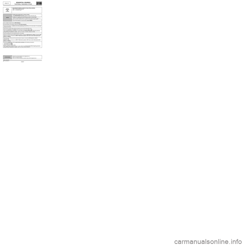
DF148
PRESENT
OR
STOREDSECONDARY BRAKE CONTACT MULTIPLEX SIGNAL
1.DEF : Communication disrupted
2.DEF : Inconsistent signal
NOTESPriorities when dealing with a number of faults:
If fault DF062 Multiplex line fault is present or stored, deal with it first.
Conditions for applying the fault finding procedure to stored faults:
The fault is declared present after the computer fault memory has been cleared, the
ignition has been switched off and on again and the engine has been started.
Use the Wiring Diagrams Technical Note for New TWINGO.
Run a multiplex network test (see 88B, Multiplex).
Run fault finding on the injection system (see 17B, Petrol injection).
Check for the presence, condition and correct positioning of the 15A fuse for the brake lights in the passenger
compartment fuse box.
Check that the indicator light switches off quickly as soon as the brake pedal moves.
Check the connection and condition of the connectors of components 120 and 160.
If the connectors are faulty and if there is a repair method (see Technical Note 6015A, Repairing electrical
wiring, W iring: Precautions for repair), repair the connectors; otherwise, replace the wiring.
Check the adjustment of the brake light switch on the pedals.
Check for continuity with the pedal depressed, between connections AP10 (track 2) and 65A of component 160.
Replace the switch if necessary (see MR 411 Mechanical systems, 83D Cruise control, Brake light switch:
Removal - Refitting).
Check there is no continuity with the pedal released, between connections AP10 (track 2) and 65A of
component 160.
Replace the switch if necessary (see MR 411 Mechanical systems, 83D Cruise control, Brake light switch:
Removal - Refitting).
Ensure the insulation to + 12 V, to earth and the continuity of the following connections:
●Connection code 3MT,
●Connection code 3MS,
between components 120 and 119.
If the connection(s) are faulty and there is a repair method (see Technical Note 6015A, Repairing electrical
wiring, W iring: Precautions for repair), repair the wiring, otherwise replace it.
AFTER REPAIRDeal with any faults detected by the diagnostic tool.
Clear the computer memory.
Carry out a road test followed by another check with the diagnostic tool.
BVRJH1_V04_DF148