ECO mode Seat Alhambra 2011 User Guide
[x] Cancel search | Manufacturer: SEAT, Model Year: 2011, Model line: Alhambra, Model: Seat Alhambra 2011Pages: 385, PDF Size: 7.92 MB
Page 147 of 385
145
Seats and storage compartments
Pull the lever to open ⇒ fig. 107.
Pr ess the cover upwards to close.
Vehicle wallet compartment
The glove compartment is designed to store the vehicle wallet.
The vehicle wallet should always be kept in the glove compartment. To store
the wallet, insert it sideways into the glove compartment.
Cooling the glove compartment
There is an air vent ⇒ fig. 108 A on the rear panel so that cooled air from
the clim at
e control system (this must be connected) is fed into the glove
compartment. Turn the air vent to open and close it. WARNING
The risk of serious injuries in the event of an accident during a sudden
brak in
g manoeuvre or turn is increased if the glove compartment is left
open.
● Keep the glove compartment closed while the vehicle is in motion. CAUTION
For structural reasons, some model versions will have gaps behind the
glov e c
ompartment into which small objects may fall. This could lead to
strange noises and damage to the vehicle. You should therefore not keep
very small objects in the glove compartment. Storage compartments in the rear floor area*
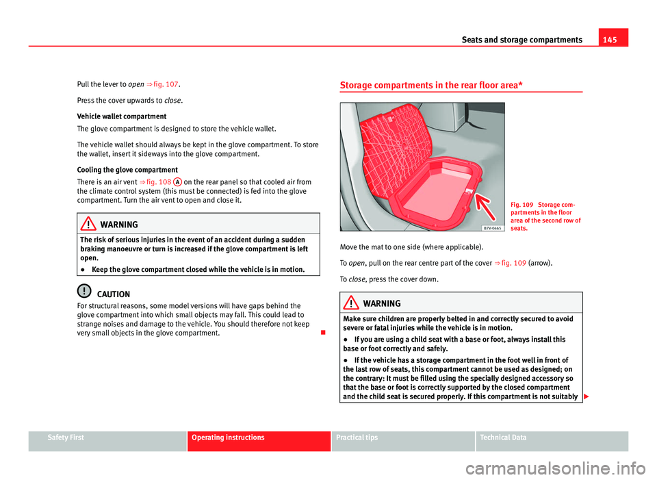
Fig. 109 Storage com-
par
tment
s in the floor
area of the second row of
seats.
Move the mat to one side (where applicable).
To open
, pull on the rear centre part of the cover ⇒ fig. 109 (arrow).
To close, press the cover down. WARNING
Make sure children are properly belted in and correctly secured to avoid
sever e or f
atal injuries while the vehicle is in motion.
● If you are using a child seat with a base or foot, always install this
base or f
oot correctly and safely.
● If the vehicle has a storage compartment in the foot well in front of
the las
t row of seats, this compartment cannot be used as designed; on
the contrary: It must be filled using the specially designed accessory so
that the base or foot is correctly supported by the closed compartment
and the child seat is secured properly. If this compartment is not suitably Safety First Operating instructions Practical tips Technical Data
Page 157 of 385
155
Heating, Ventilation and Air conditioning
Heating, Ventilation and Air conditioning Climate Control
Introduction Viewing Climatronic information
The fact
or
y-fitted radio or navigation system screen briefly displays informa-
tion relating to Climatronic.
The units of temperature measurement is displayed on the factory-installed
radio or navigation system and, depending on the vehicle equipment, can
be set using the Configuration menu on the instrument panel.
Additional information and warnings:
● SEAT information system ⇒ page 62
● W
indscreen wash system ⇒ page 105
● Aux
iliary heating ⇒ page 163
● C
aring for and cleaning the vehicle exterior ⇒ page 242WARNING
Reduced visibility through the windows increases the risk of serious acci-
dents.
● Ens
ure that all windows are free of ice and snow and that they are not
fogg
ed up preventing a clear view of everything outside.
● The maximum heat output required to defrost windows quickly is only
avail
able when the engine has reached its normal running temperature.
Only drive when you have good visibility. WARNING (Continued)
● Always ensure that you use the climate control and heated rear win-
do w t
o maintain good visibility.
● Never leave the air recirculation on for a long period of time. If the
coolin
g mode is switched off and air recirculation mode switched on, the
windows can mist over very quickly, considerably limiting visibility.
● Switch air recirculation mode off when it is not required. WARNING
Stuffy or used air will increase fatigue and reduce driver concentration
pos s
ibly resulting in a serious accident.
● Never leave the fresh air fan turned off or use the air recirculation for
long periods
of time; the air inside the passenger compartment will not
be refreshed. CAUTION
● Switch the climate control system off if you think it may be broken. This
w i
ll avoid additional damage. Have the climate control system checked by a
Technical Service.
● Repairs to the climate control system require specialist knowledge and
speci
al tools. SEAT recommends visiting a Technical Service.
● Do not smoke when air recirculation is switched on in vehicles with a cli-
mate c
ontrol system. The smoke taken in could lie on the cooling system va-
poriser and on the activated charcoal cartridge of the dust and pollen filter,
leading to a permanently unpleasant smell. Safety First Operating instructions Practical tips Technical Data
Page 160 of 385
158
Heating, Ventilation and Air conditioning
Some Climatronic controls may also be on the climate control system con-
tro l
panel located in the rear centre console. These controls are used to
make the appropriate settings for the rear seats. Control
butt on Additional information. Climatic
⇒ fig. 121; Climatr
onic
⇒ fig. 122. 1
Tem-
perat ur
e
... Climatic: rotate the control to adjust the temperature accord-
in
gly
.
Climatronic: the settings for the left hand side, the right-hand
side and the rear seats are made separately. Rotate the con-
trol to adjust the temperature accordingly. The temperature is
indicated on the outside ring. 2
Fan
... Climatic: setting 0, f
an and C
limatic switched off;
setting 4, fan set to maximum.
Climatronic: the Fan speed is automatically adjusted depend-
ing on the vehicle speed to avoid annoying noises. The fan
can also be adjusted manually. 3
Air dis-
tribution Climatic: rotate the continuous control to direct the airflow to
the de
s
ired area.
Climatronic: manually adjustable using the controls. Climatic: defro
s
t function. The airflow is directed at the wind-
screen. In this position, air recirculation is automatically
switched off or is not switched on. Climatronic: defro
s
t function. The air drawn in from outside
the vehicle is directed at the windscreen and air recirculation
is automatically switched off. To defrost the windscreen more
quickly, the air is dehumidified at temperatures over approxi-
mately +1.5°C (+35°F) and the fan runs at maximum output. The air is directed at the chest of driver and passengers by the
da
shbo
ard air vents. – Air distribution towards the footwell.
Air distribution towards the windscreen and the footwell.
AC Climatic, Climatronic: Pre
s
s the button to turn off/on cooling. Control
butt on Additional information. Climatic
⇒ fig. 121; Climatr
onic
⇒ fig. 122. Heated rear window: this only works when the engine is run-
ning and sw
it
ches off automatically after a maximum of 10 mi-
nutes. Air recirculation mode ⇒ pag
e 161. Climatronic: Autom
atic
air recirculation ⇒ page 161. Windscreen heating: only works when the engine is running
and swit
c
hes off automatically after a few minutes. Instant auxiliary heating on/off button
⇒ page 163. Switching
off
OFF Climatic: turn the fan switch to setting 0.
C
lim
atronic: press the OFF button or set the fan manually to
0. When the sy s
tem switches off, the OFF button will light up.
REAR Climatronic: pre
s
s the REAR button to adjust the climate con-
tro l
for the rear seats from the front. The REAR button will light
up when the fu nction i
s switched on. The settings for the rear
seats will be displayed. Press the button again to switch the
function off or do not touch any other button for around 10
seconds. REST Climatronic: pre
s
s the button REST to use residual heat. When
the engine i s
still warm but the ignition switched off, the heat
given off by the engine can be used to keep the passenger
compartment warm. The REST button will light up when the
fu nction i
s switched on. The function will switch off after
around 30 minutes and if the battery level is low.
Page 164 of 385
162
Heating, Ventilation and Air conditioning
Switching air recirculation mode on and off manually
Swit c
hing on: press the corresponding button until the light under the sym-
bol comes on.
Switching off: press the button until no indicator remains lit.
Automatic air recirculation mode
Fresh air enters the vehicle interior in position . If the system detects a
high concentration of hazardous substances in the ambient air, air recircu-
lation mode is switched on automatically. When the level of impurities
drops to within a normal range, recirculation mode is switched off.
The system is unable to detect unpleasant smells.
Air recirculation mode is not automatically switched on in the following ca-
ses of outside temperatures and conditions:
● The cooling system is switched on (the AC button is lit up) and the out-
side t emper
ature is below +3°C (+38°F).
● The cooling system and the windscreen wipers are switched off and the
outside temper
ature is below +10°C (+50°F).
● The cooling system is switched on, the outside temperature is below
+15°C (+59°F) and the wind
screen wipers are switched on.
Switching the automatic air recirculation mode on and off
Switching on: press the button until the light under the symbol
come s
on.
Switching off: press the button until no button remains lit.
Swit c
hing the automatic air recirculation mode off temporarily
● Press the button once to temporarily switch to manual air recircula-
tion mode in the event of
unpleasant smells from outside. The control light
under the symbol comes on.
● After more than two seconds, press the
button again to restart au-
tom atic
air recirculation. The control light under the symbol comes on. WARNING
Stuffy or used air will increase fatigue and reduce driver concentration
pos s
ibly resulting in a serious accident.
● Never use recirculation mode for long periods as it does not refresh
the air inside the
vehicle.
● If the cooling mode is switched off and air recirculation mode switch-
ed on, the window
s can mist over very quickly, considerably limiting visi-
bility.
● Switch air recirculation mode off when it is not required. CAUTION
Do not smoke when air recirculation is switched on in vehicles with a cli-
mat e c
ontrol system. The smoke taken in could lie on the cooling system va-
poriser and on the activated charcoal cartridge of the dust and pollen filter,
leading to a permanently unpleasant smell. Note
Air recirculation mode switches on to prevent exhaust gas from entering the
vehic l
e interior when it is in reverse and while the automatic windscreen
wash and wipe is working.
Page 166 of 385
164
Heating, Ventilation and Air conditioning
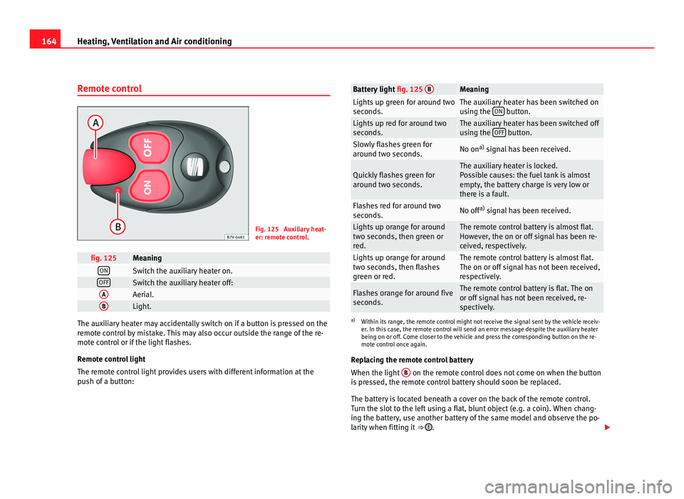
Remote control Fig. 125 Auxiliary heat-
er: remot
e c
ontrol. fig. 125 Meaning
ON
Switch the auxiliary heater on.
OFF
Switch the auxiliary heater off:
A
Aerial.
B
Light.
The auxiliary heater may accidentally switch on if a button is pressed on the
remot
e c
ontrol by mistake. This may also occur outside the range of the re-
mote control or if the light flashes.
Remote control light
The remote control light provides users with different information at the
push of a button: Battery light
fig. 125 B Meaning
Lights up green for around two
second
s. The auxiliary heater has been switched on
us
in
g the ON button.
Lights up red for around two
second
s. The auxiliary heater has been switched off
us
in
g the OFF button.
Slowly flashes green for
arou
nd tw
o seconds. No on
a)
signal has been received. Quickly flashes green for
arou
nd tw
o seconds. The auxiliary heater is locked.
Po
s
sible causes: the fuel tank is almost
empty, the battery charge is very low or
there is a fault. Flashes red for around two
second
s. No off
a)
signal has been received. Lights up orange for around
two sec
ond
s, then green or
red. The remote control battery is almost flat.
How
ev
er, the on or off signal has been re-
ceived, respectively. Lights up orange for around
two sec
ond
s, then flashes
green or red. The remote control battery is almost flat.
The on or off s
ign
al has not been received,
respectively. Flashes orange for around five
second
s. The remote control battery is flat. The on
or off s
ign
al has not been received, re-
spectively. a)
Within its range, the remote control might not receive the signal sent by the vehicle receiv-
er. In thi s
case, the remote control will send an error message despite the auxiliary heater
being on or off. Come closer to the vehicle and press the corresponding button on the re-
mote control once again.
Replacing the remote control battery
When the light B on the remote control does not come on when the button
is pr
essed, the remote control battery should soon be replaced.
The battery is located beneath a cover on the back of the remote control.
Turn the slot to the left using a flat, blunt object (e.g. a coin). When chang-
ing the battery, use another battery of the same model and observe the po-
larity when fitting it ⇒ .
Page 183 of 385
181
Driving
● You should reduce speed accordingly.
● Pre
ss the selector lever from position D to the right int
o the Tiptronic se-
lector gate ⇒ page 180.
● Gently pull the selector lever back to change down a gear.
● ALTERNATIVELY: Reduce u
sing the steering wheel paddles ⇒ page 180.
Emergency program
If all the selector lever positions on the instrument panel display are shown
with a light-coloured background, this means there is a fault in the system.
The automatic gearbox will operate in emergency programme mode. When
the emergency program is activated, it is possible to drive the vehicle how-
ever, at low speeds and within a selected range of gears.
For the DSG ®
dual clutch gearbox, in some cases, this may mean that re-
verse gear does not engage . The gearbox should be checked by a Technical
Service as soon as possible.
Overload protection for the 6-speed DSG gearbox ®
When the clutch is overloaded, the vehicle begins to jerk and the selector
lever position indicator begins to flash. To prevent damage to the clutch,
this interrupts the power transmission between the engine and the gearbox.
There is no more traction and it is not possible to accelerate. If the clutch is
opened automatically due to overloading, press the brake pedal. Wait a few
seconds before starting to move again.
Kick-down
The kick-down system provides maximum acceleration when the gear selec-
tor lever is in the positions D, S or in the Tiptronic position.
When the accelerator pedal is pressed right down, the automatic gearbox
will shift down to a lower gear, depending on road speed and engine speed.
This takes advantage of the maximum acceleration of the vehicle ⇒ .
When the acc el
erator is pressed to the floor, the automatic gearbox shifts to
the next gear only after the engine reaches the specified maximum engine
speed. Launch-Control Programme
The Launch-C
ontrol programme enables maximum acceleration while at a
standstill.
● Deactivate the ASR (TCS) ⇒ page 183.
● Pr
ess and hold the brake pedal with your left foot.
● Place the selector lever in position S or Tiptronic
.
● Press the accelerator with the right foot until the vehicle reaches an en-
gine speed of ap
proximately 3200 rpm.
● Lift the left foot off the brake ⇒ . The vehicle starts with maximum ac-
cel er
ation.
● Turn on the ASR (TCS) after accelerating! WARNING
Rapid acceleration can cause loss of traction and skidding, especially on
slip per
y ground. This could cause loss of control of the vehicle resulting
in an accident and considerable damage.
● Only use kick-down and rapid acceleration when weather conditions,
surf
ace conditions and traffic conditions permit; accelerate and drive in a
manner that does not endanger other road users.
● Please remember that the drive wheels can slip and the vehicle can
skid if the ASR (T
CS) is turned off, especially on slippery ground.
● Turn on the ASR (TCS) after accelerating. CAUTION
● If you stop on a hill with a gear ratio engaged, do not try to prevent the
v ehic
le from rolling back by pressing on the accelerator. This could cause
overheating and damage the automatic gearbox.
● Never allow the vehicle to move with the gear selector lever in N, espe-
c
ially with the engine turned off. The automatic gearbox will not be lubrica-
ted and could be damaged. Safety First Operating instructions Practical tips Technical Data
Page 189 of 385
187
Driving
● On slopes, turn the front wheels so that they are against the edge of the
k erb
.
● Uphill, turn the wheels towards the centre of the road. WARNING
The components of the exhaust system reach very high temperatures.
This c
ould cause a fire and considerable damage.
● Always park your vehicle so that no part of the exhaust system can
come in cont
act with flammable materials (such as wood, leaves, spilled
fuel, dried grass, etc). CAUTION
● Special care should be taken when parking in areas with high kerbs or
fi x
ed barriers. Objects protruding from the ground may damage the bumper
or other parts of the vehicle during manoeuvres. To avoid damage, stop be-
fore the wheels touched the barrier or kerb.
● Special attention is required when driving through entrances, over
ramps, k
erbs or other objects. The vehicle underbody, bumpers, mudguards
and running gear, and the engine and exhaust system could be damaged as
you drive over these objects.
Information about the brakes For the first 200 to 300 km (100 to 200 miles),
new brake p
ads have not yet
reached their maximum braking capacity, and need to be “run in” first ⇒ .
The slightly r
educed braking effect can be compensated for by increasing
pressure on the brake pedal. While running in, the full braking distance or
emergency braking distance is larger then when the brake pads have been
run in. While running in, avoid full power braking or situations requiring
braking performance. For example, in heavy traffic. The rate of wear of the brake pads
depends
to a great extent on the condi-
tions in which the vehicle is used and the way the vehicle is driven. If the
vehicle is used frequently in city traffic or for short trips or driven sport style,
visit a specialist workshop regularly more frequently than advised in the
Maintenance Programme to have the bake pads checked.
If you drive with wet brakes, for example, after crossing areas of water, in
heavy rainfall or even after washing the car, the effect of the brakes is less-
ened as the brake discs are wet or even frozen (in winter). At higher speed,
dry the brakes as quickly as possible by braking gently several times. Only
do this without endangering vehicles behind you or any other road users
⇒ .
A la y
er of salt on the discs and brake pads will reduce brake efficiency and
increase braking distance. If you drive for a prolonged period on salted
roads without braking then brake carefully several times to eliminate the
layer of salt on the brakes ⇒ .
If the v
ehicle remains parked for considerable lengths of time, is used little,
or if the brakes are not used, there may be corrosion on the brake discs and
a buildup of dirt on the brake pads. If the brakes are not used frequently, or
if rust has formed on the discs, SEAT recommends cleaning the pads and
discs by braking firmly a few times at a moderately high speed. Only do this
without endangering vehicles behind you or any other road users ⇒ .
Fau lt
s in the brake system
During braking, if you notice that the vehicle does not react as usual (that
the braking distance has increased suddenly) it may be possible that there
is a fault in the braking system. The warning lamp lights up and a text
message displayed. Take the vehicle to a Technical Service immediately and
have the fault repaired. Drive at a moderate speed and be prepared to use
more pressure on the brake pedal, and allow for longer stopping distances.
Brake servo
The brake servo only operates when the engine is running and the pressure
applied by the driver on the brake pedal increases. Safety First Operating instructions Practical tips Technical Data
Page 194 of 385
192
Driving
notably increasing braking distance, and could even result in the total fail-
ure of the br
ake system. Ensuring that the brake system is always function-
ing correctly is essential for your own safety and the safety of other road
users ⇒ .
Brak e fluid s
pecifications
SEAT have developed a special brake fluid optimised for the brake systems
of their vehicles. To ensure the optimum working of the brake system, SEAT
recommends the use of brake fluid in accordance with the VW 501 14
standard. If this brake fluid is not available or another brake fluid is used for
different reasons, use a brake fluid that complies with the United States
standard FMVSS 116 DOT 4 or the German standard DIN ISO 4925 CLASS 4
⇒ .
Brak e fluid
s conforming to the standard VW 501 14, fulfil the American re-
quirements of the FMVSS 116 DOT 4 standard and the German
DIN ISO 4925 CLASS 4 standard. However, fluids that comply with the Amer-
ican FMVSS 116 DOT 4 standard or the German DIN ISO 4925 CLASS 4
standard do not necessarily comply with the VW 501 14 standard. Always
check the information on the brake fluid container and ensure that you are
using suitable brake fluid.
A suitable brake fluid can be obtained from Authorised Service Centres.
Brake fluid level
The level of the brake fluid should always be between the MIN and MAX
marks, or above the MIN mark ⇒ .
It i s
not always possible to check the level of the brake fluid, as in some
models the engine components make it difficult to see the brake fluid reser-
voir. If you cannot read the exact brake fluid level, consult a specialist.
The brake fluid level drops slightly when the vehicle is being used due to
wear of the brake pads and the automatic readjustment of the brake.
Changing the brake fluid
The brake fluid should be changed in accordance with the instructions giv-
en in the Maintenance Programme. Have the brake fluid changed by a Tech- nical Service. SEAT recommends visiting a Technical Service. This means
that on
ly brake fluid complying with the required specifications will be
used. WARNING
If the brake fluid level is low or unsuitable/old brake fluid is used, the
brak e sy
stem may fail or braking power will be reduced.
● Check the brake system and the brake fluid level regularly!
● The brake fluid should be changed regularly in accordance with the
instruction
s given in the Maintenance Programme.
● When the brake fluid is used and brakes are subjected to extreme
brakin
g forces, bubbles of vapour form in the brake system. These bub-
bles of water vapour can significantly reduce braking power, notably in-
creasing braking distance, and could even result in the total failure of the
brake system.
● Only used brake fluid that conforms to the VW 501 14 standard,
FMVS
S 116 DOT 4 standard or even the DIN ISO 4925 CLASS 4 standard.
Other types of brake fluid could affect brake operation and reduce brak-
ing power. Do not use a brake fluid if the container does not specify com-
pliance with the VW 501 14, FMVSS 116 DOT 4 or DIN ISO 4925 CLASS 4
standards.
● The replacement brake fluid must be new.
● Always ensure that you use suitable brake fluid. Do not use a brake
fluid if the cont
ainer does not specify compliance with the VW 501 14,
FMVSS 116 DOT 4 or DIN ISO 4925 CLASS 4 standards.
Page 205 of 385
203
Driving
● To ensure that the system works properly, the bumper sensors must be
k ept
clean, free of ice and snow and uncovered.
● The bumper sensors may become damaged or misaligned, for example,
when parkin
g.
● When cleaning the sensors with high-pressure or steam cleaning equip-
ment, spra
y the sensors briefly at a distance of no less than 10 cm. Note
Contact a specialist workshop with any system faults. SEAT recommends
vi s
iting a Technical Service.
Parking using the park assist system Fig. 144 Detailed view of
the centr
e c
onsole: but-
ton to switch the park as-
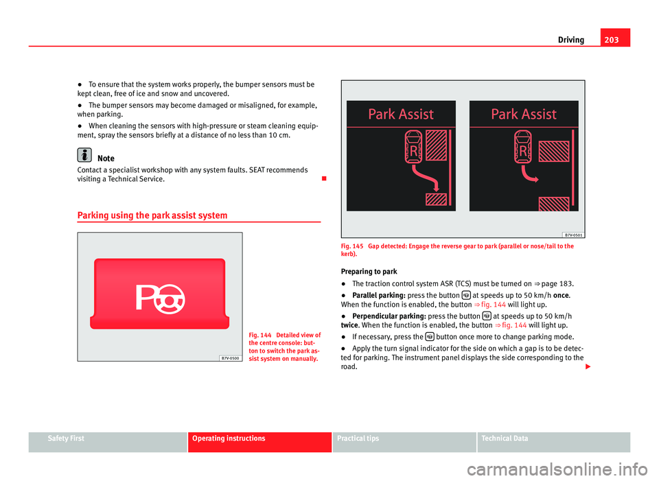
sist system on manually. Fig. 145 Gap detected: Engage the reverse gear to park (parallel or nose/tail to the
kerb).
Pr ep
aring to park
● The traction control system ASR (TCS) must be turned on ⇒ page 183.
● P
arallel parking: pres
s the button at speeds up to 50 km/h
once.
When the f
unction is enabled, the button ⇒ fig. 144 will light up.
● Perpendicular parking: pres
s the button at speeds up to 50 km/h
twic e
. When the function is enabled, the button ⇒ fig. 144 will light up.
● If necessary, press the button once more to change parking mode.
● Apply the turn signal indicator for the side on which a gap is to be detec-
ted f or p
arking. The instrument panel displays the side corresponding to the
road. Safety First Operating instructions Practical tips Technical Data
Page 209 of 385
207
Driving
Rear Assist system*
Introduction The camera fitted to the tailgate helps drivers during parking or reversing
manoeu
vr
es. The camera image and certain orientation points generated by
the system are indicated on the factory-fitted radio or navigation system
screen.
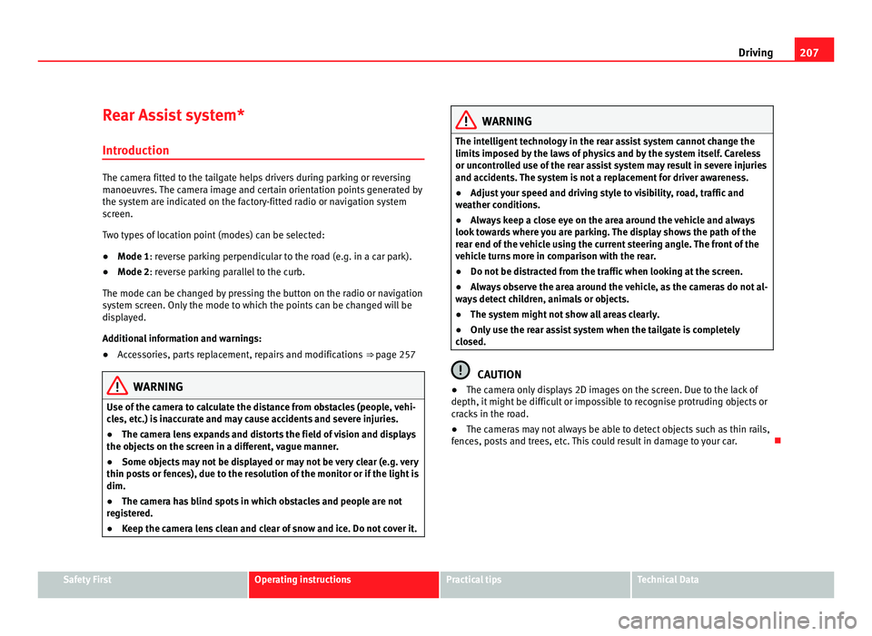
Two types of location point (modes) can be selected:
● Mode 1: reverse parking perpendicular to the road (e.g. in a car park).
● Mode 2: r
everse parking parallel to the curb.
The mode can be c
hanged by pressing the button on the radio or navigation
system screen. Only the mode to which the points can be changed will be
displayed.
Additional information and warnings:
● Accessories, parts replacement, repairs and modifications ⇒ page 257WARNING
Use of the camera to calculate the distance from obstacles (people, vehi-
cl e
s, etc.) is inaccurate and may cause accidents and severe injuries.
● The camera lens expands and distorts the field of vision and displays
the obj
ects on the screen in a different, vague manner.
● Some objects may not be displayed or may not be very clear (e.g. very
thin post
s or fences), due to the resolution of the monitor or if the light is
dim.
● The camera has blind spots in which obstacles and people are not
regi
stered.
● Keep the camera lens clean and clear of snow and ice. Do not cover it. WARNING
The intelligent technology in the rear assist system cannot change the
limits impo
sed by the laws of physics and by the system itself. Careless
or uncontrolled use of the rear assist system may result in severe injuries
and accidents. The system is not a replacement for driver awareness.
● Adjust your speed and driving style to visibility, road, traffic and
weather c
onditions.
● Always keep a close eye on the area around the vehicle and always
look to
wards where you are parking. The display shows the path of the
rear end of the vehicle using the current steering angle. The front of the
vehicle turns more in comparison with the rear.
● Do not be distracted from the traffic when looking at the screen.
● Always observe the area around the vehicle, as the cameras do not al-
way
s detect children, animals or objects.
● The system might not show all areas clearly.
● Only use the rear assist system when the tailgate is completely
closed. CAUTION
● The camera only displays 2D images on the screen. Due to the lack of
depth, it might
be difficult or impossible to recognise protruding objects or
cracks in the road.
● The cameras may not always be able to detect objects such as thin rails,
fence
s, posts and trees, etc. This could result in damage to your car. Safety First Operating instructions Practical tips Technical Data