Seat Alhambra 2011 Owner's Manual
Manufacturer: SEAT, Model Year: 2011, Model line: Alhambra, Model: Seat Alhambra 2011Pages: 385, PDF Size: 7.92 MB
Page 211 of 385
209
Driving
Things to note 1) Do not use the rear assist system in the following cases:
– If there is a fault in the dynamic chassis control (DCC).
– If the image displayed is not very clear or reliable (low visibility or dirty
len
s). – If the space behind the vehicle cannot be clearly or completely recog-
nised.
– If the vehicle has been overloaded at the rear.
– If the driver is not familiar with the system.
– If the tailgate is open.
– If the position and installation angle of the camera have been changed,
e.g. in a r
e
ar-end collision. Have a specialised workshop check the system. 2) Optical illusions of the camera (examples)
The rear assist camera produces two-dimensional images. Any cracks in or
ob
j
ects protruding from the ground or from other vehicles are more diffi-
cult to spot or cannot be seen due to a lack of depth in the image dis-
played. Objects or other vehicles may seem to be closer or further away than what
they r
e
ally are: – On changing from a flat surface to a slope or gradient.
– On changing from a slope or gradient to a flat surface.
– If the vehicle has been overloaded at the rear.
– On approaching protruding objects. These objects may be outside the
angl
e of
vision of the camera when reversing. Cleaning the camera lens
Keep the c
amer
a lens clean and clear of snow and ice:
● Moisten the lens using a commercially available, alcohol-based glass
cle
aning agent and clean the lens with a dry cloth ⇒ .
● Remove snow using a small brush.
● Use de-icing spray to remove any ice ⇒ . CAUTION
● Never use abrasive cleaners to clean the camera lens.
● Nev er r
emove snow or ice from the camera lens using warm or hot water.
This c
ould damage the lens. Note
● SEAT recommends that you practise parking with the rear assist system
in a quiet loc
ation or in a car park to become familiar with the system, in-
cluding the orientation lines and their function.
● The orientation lines will not be displayed on the screen if the tailgate is
open or the factor
y-fitted towing bracket is electrically connected to a trailer.
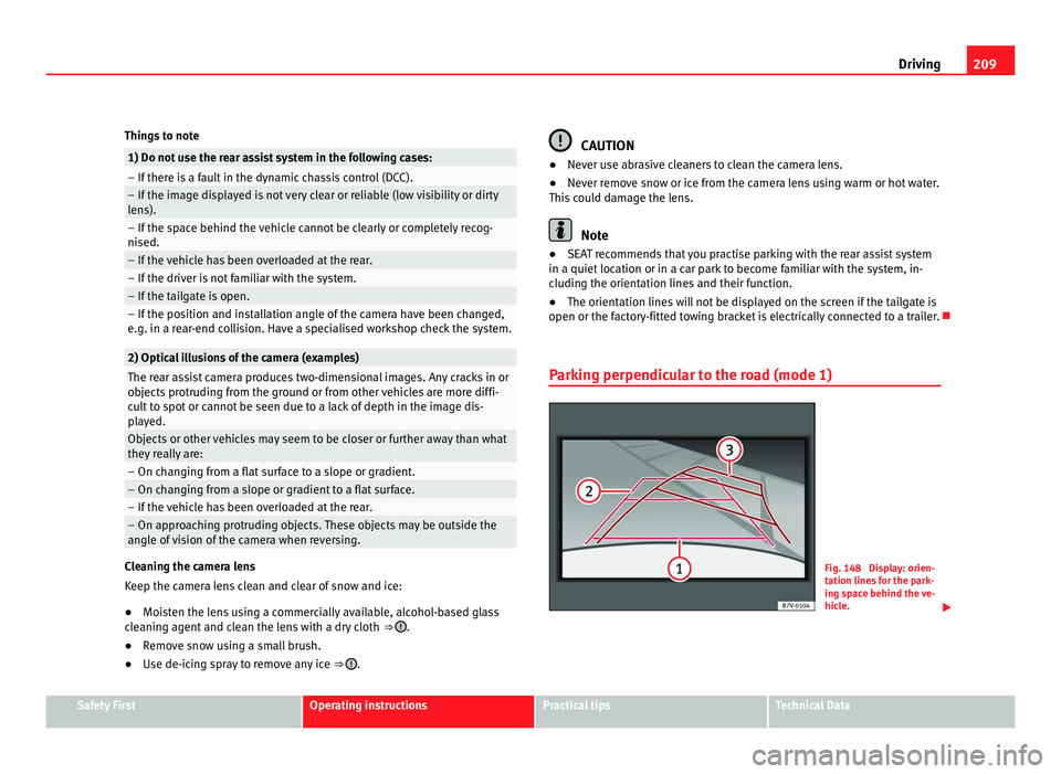
Parking perpendicular to the road (mode 1) Fig. 148 Display: orien-
tation line
s
for the park-
ing space behind the ve-
hicle. Safety First Operating instructions Practical tips Technical Data
Page 212 of 385
210
Driving
Summary of the orientation points
Me anin
g of orientation lines displayed on the screen ⇒ fig. 148. All of the
lengths of the orientation lines use a vehicle located on a horizontal surface
as reference.
Red Safety distance: road area located up to around 40 cm behind the
vehicle.
Green: prolongation of the rear of the vehicle (somewhat enlarged). The
area displayed green ends around two metres behind the vehicle, on
the road.
Yellow: prolongation of the rear of the vehicle as the steering wheel
turns. The area displayed yellow ends around three metres behind the
vehicle, on the road.
Parking the vehicle
● Stop the vehicle in front of a space and select reverse gear.
● Reverse slowly and turn the steering wheel so that the yellow orientation
lines guide
you towards the space 3 .
● Align the vehicle straight in the parking place using the help of the
green orient ation line
s.
1 2
3 Parking parallel to the road (mode 2)
Fig. 149 Display: orien-
tation line
s
and surfaces
for the space behind the
vehicle.
After applying the turn signal indicator, the lines and surfaces not required
are delet
ed.
Summary of the orientation points
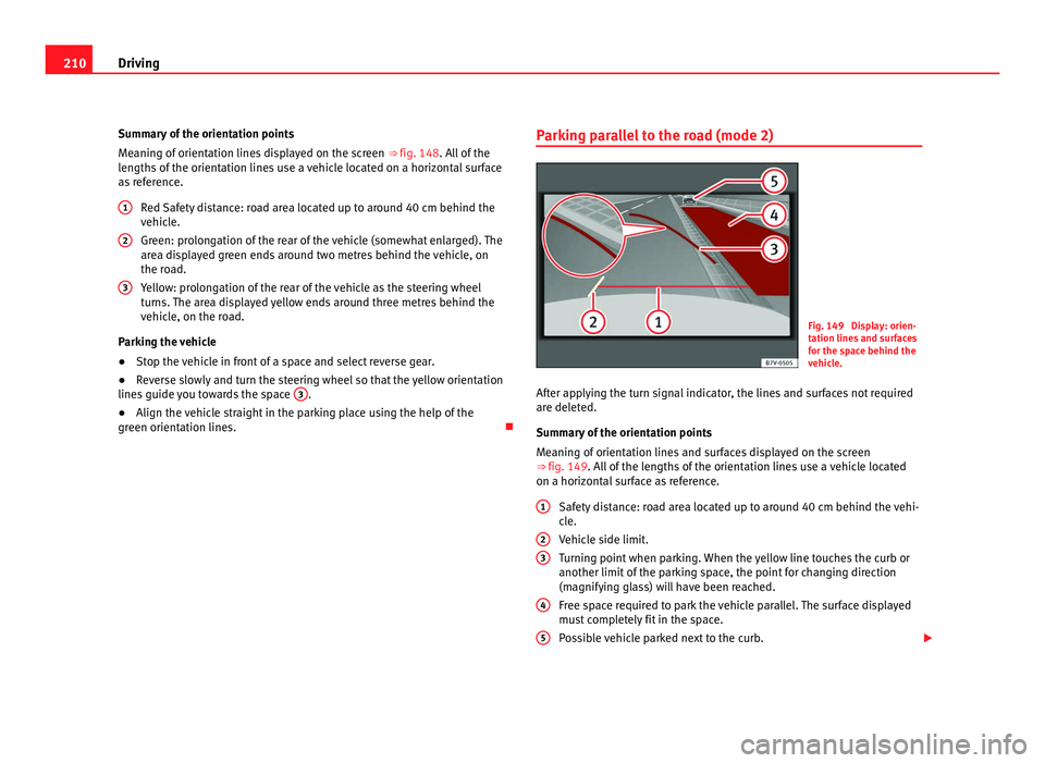
Meaning of orientation lines and surfaces displayed on the screen
⇒ fig. 149. All of the lengths of the orientation lines use a vehicle located
on a horizontal surface as reference.
Safety distance: road area located up to around 40 cm behind the vehi-
cle.
Vehicle side limit.
Turning point when parking. When the yellow line touches the curb or
another limit of the parking space, the point for changing direction
(magnifying glass) will have been reached.
Free space required to park the vehicle parallel. The surface displayed
must completely fit in the space.
Possible vehicle parked next to the curb.
1 2
3
4
5
Page 213 of 385
211
Driving
Parking the vehicle
● Stop the vehicle 1 m away parallel to the parking space and select re-
ver se g
ear.
● Switch on mode 2 on the navigation system screen for parallel parking.
● Slowly reverse and turn the steering wheel so that the surface displayed
yello
w on the screen stops in front of any obstacles 5 (e.g. another vehi-
cl e).
● T
urn the steering wheel fully towards the space and reverse slowly.
● When the yellow line 3 touches the side limit of the space, e.g. the bor-
der or curb (m agnif
ying glass), turn the steering wheel fully in the opposite
direction.
● Continue reversing until the vehicle is inside the space, parallel to the
roa
d. Correct the position if necessary. Safety First Operating instructions Practical tips Technical Data
Page 214 of 385
212
Driving
Cruise control system*
Introduction The cruise control system (CCS) is able to maintain the set speed when driv-
ing f
or
wards from approx. 20 km/h (12 mph).
The CCS only slows down by reducing the accelerator but not by braking.
⇒ .
Addition a
l information and warnings:
● Changing gear ⇒ page 174
● A
ccessories, parts replacement, repairs and modifications ⇒ page 257WARNING
Use of the cruise control could cause accidents and severe injuries if it is
not po s
sible to drive at a constant speed maintaining the safety distance.
● Do not use the CCS in heavy traffic, if the distance from the vehicle in
front i
s insufficient, on steep roads, with several bends or in slippery cir-
cumstances (snow, ice, rain or loose gravel), or on flooded roads.
● Never use the CCS when driving off-road or on unpaved roads.
● Always adapt your speed and the distance to the vehicles ahead in
line with v
isibility, weather conditions, the condition of the road and the
traffic situation.
● To avoid unexpected operation of the cruise control system, turn it off
every
time you finish using it.
● It is dangerous to use a set speed which is too high for the prevailing
roa
d, traffic or weather conditions.
● When travelling down hills, the CCS cannot maintain a constant
speed. The
vehicle tends to accelerate under its own weight. Select a
lower gear or use the foot brake to slow the vehicle. Warning and control lamp
Fig. 150 Dash panel display: CCS status indications.
lights up Possible cause Solution
This cruise control system
maint
ain
s the set speed of
the vehicle. –
Several warning and control lamps should light up for a few seconds when
the ignition is
sw
itched. This signals that the lamp is working properly. They
will switch off after a few seconds.
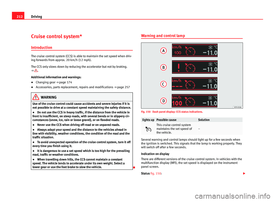
Indication on display
There are different versions of the cruise control system. In vehicles with the
multifunction display (MFI), the set speed is displayed on the instrument
panel screen.
Status fig. 150:
Page 215 of 385
213
Driving
CCS temporarily switched off. The set speed is displayed in small fig-
ure s.
S
ystem error. Contact a specialist workshop.
CCS switched on. The speed memory is empty.
The CCS is switched on. The set speed is displayed in large figures. WARNING
If the warning lamps and messages are ignored, the vehicle may stall in
traffic, or m a
y cause accidents and severe injuries.
● Never ignore the warning lamps or text messages.
● Stop the vehicle safely as soon as possible. CAUTION
Failure to heed the warning lamps and text messages when they appear
ma y
result in faults in the vehicle.
A B
C
D Cruise control operation
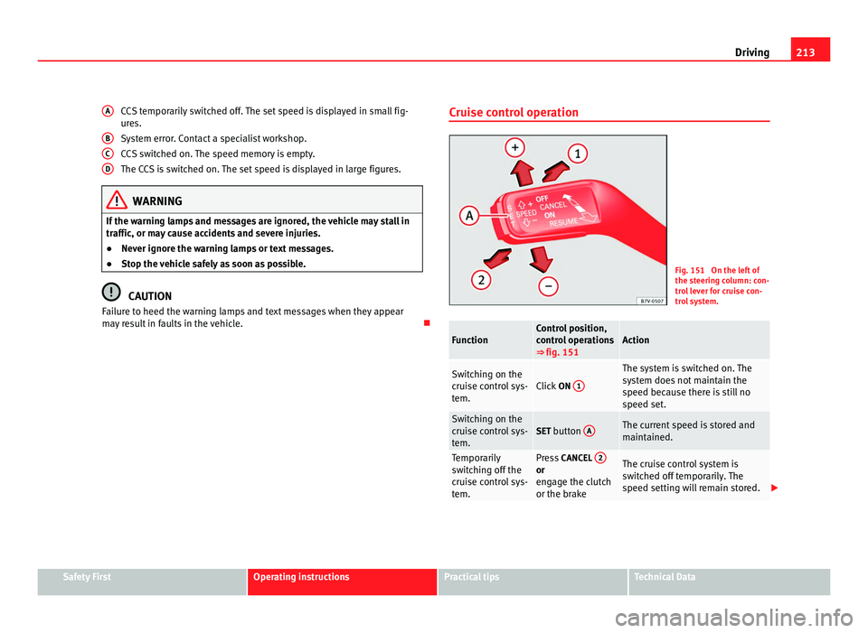
Fig. 151 On the left of
the st
eerin
g column: con-
trol lever for cruise con-
trol system. Function Control position,
contr
o
l operations
⇒ fig. 151 Action
Switching on the
crui
se c
ontrol sys-
tem. Click
ON 1 The system is switched on. The
sys
t
em does not maintain the
speed because there is still no
speed set. Switching on the
crui
se c
ontrol sys-
tem. SET button
A The current speed is stored and
maint
ained. Temporarily
swit
c
hing off the
cruise control sys-
tem. Press
CANCEL 2 or
eng
ag
e the clutch
or the brake The cruise control system is
swit
c
hed off temporarily. The
speed setting will remain stored. Safety First Operating instructions Practical tips Technical Data
Page 216 of 385
214
Driving Function Control position,
contr
o
l operations
⇒ fig. 151 Action
Switching the
speed settin
g
b
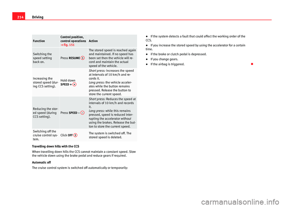
ack on. Press
RESUME 1 The stored speed is reached again
and maint
ained. If
no speed has
been set then the vehicle will re-
cord and maintain the actual
speed of the vehicle. Increasing the
st
or
ed speed (dur-
ing CCS setting). Hold down
SPEED + + Short press:
Incre
ases the speed
at intervals of 10 km/h and re-
cords it.
Long press: the vehicle acceler-
ates while the button remains
pressed. Release the button to
store the current speed. Reducing the stor-
ed speed (durin
g
C
CS setting). Press
SPEED – – Short press:
Reduce
s the speed at
intervals of 10 km/h and records
it.
Long press: while this remains
pressed, speed is reduced inter-
rupting the accelerator without
using the brakes. Release the but-
ton to store the current speed. Switching off the
crui
se c
ontrol sys-
tem. Click
OFF 2 The system is switched off. The
st
or
ed speed is deleted. Travelling down hills with the CCS
When trav
el
ling down hills the CCS cannot maintain a constant speed. Slow
the vehicle down using the brake pedal and reduce gears if required.
Automatic off
The cruise control system is switched off automatically or temporarily: ●
If the system detects a fault that could affect the working order of the
CC
S.
● If you increase the stored speed by using the accelerator for a certain
time.
● if the brake or clutch pedal is depressed.
● If you change gears.
● If the airbag is triggered.
Page 217 of 385
215
Driving
Lane Assist system* Introduction Additional information and warnings:
●
SEAT information system ⇒ pag e 62
● A
ccessories, parts replacement, repairs and modifications ⇒ page 257WARNING
The intelligent technology in the lane assist system cannot change the
limits impo
sed by the laws of physics and by the system itself. Careless
or uncontrolled use of the lane assist system may cause accidents and in-
jury. The system is not a replacement for driver awareness.
● Always adapt your speed and the distance to the vehicles ahead in
line with v
isibility, weather conditions, the condition of the road and the
traffic situation.
● Always keep your hands on the steering wheel so you can turn it at
any time.
● The l
ane assist system does not detect all road markings. In some cir-
cumst
ances, the poor state of the road, structures located on it or certain
objects may be mistakenly recognised as road markings by the lane as-
sist system. In such situations, switch the lane assist system off immedi-
ately.
● Pay attention to the instructions on the instrument panel display and
act acc
ordingly to its requests.
● Always pay attention to the vehicle's surroundings. Note
The lane assist system has been exclusively developed for driving on as-
phalt ed r
oads. Note
If the lane assist system does not work as described in this chapter, do not
use it and c
ontact a specialist workshop. Note
If you observe any system malfunction, have the system checked by a speci-
alised w ork
shop. Safety First Operating instructions Practical tips Technical Data
Page 218 of 385
216
Driving
Control lamps Blinks or lights
up Possible cause Solution
(yellow) Lane assist system con-
nected b
ut
inactive. The system cannot clearly
detect
the l
ane. See and
page 217, The lane assist
system is inactive (control
lamp lit in yellow). (green) Lane assist system con-
nected and activ
e. –
Several warning and control lamps should light up for a few seconds when
the ignition is
sw
itched. This signals that the lamp is working properly. They
will switch off after a few seconds. WARNING
If the warning lamps and messages are ignored, the vehicle may stall in
traffic, or m a
y cause accidents and severe injuries.
● Never ignore the warning lamps or text messages.
● Stop the vehicle safely as soon as possible. CAUTION
Failure to heed the warning lamps and text messages when they appear
ma y
result in faults in the vehicle. Operation mode
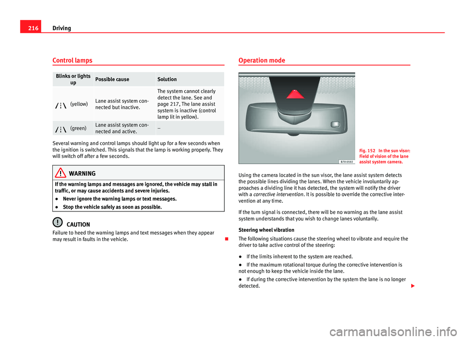
Fig. 152 In the sun visor:
Field of
vision of the lane
assist system camera.
Using the camera located in the sun visor, the lane assist system detects
the poss
ible lines dividing the lanes. When the vehicle involuntarily ap-
proaches a dividing line it has detected, the system will notify the driver
with a corrective intervention. It is possible to override the corrective inter-
vention at any time.
If the turn signal is connected, there will be no warning as the lane assist
system understands that you wish to change lanes voluntarily.
Steering wheel vibration
The following situations cause the steering wheel to vibrate and require the
driver to take active control of the steering:
● If the limits inherent to the system are reached.
● If the maximum rotational torque during the corrective intervention is
not enough to k
eep the vehicle inside the lane.
● If during the corrective intervention by the system the lane is no longer
detected.
Page 219 of 385
217
Driving
Switching the lane assist system on or off
● Select the corresponding menu option using the button for the driver as-
si s
t systems ⇒ page 62.
● ALTERNATIVELY: Activat
e or deactivate the system in the menu Settings,
sub-menu Assist systems , menu Lane Assist ⇒ page 62. The “confirmation
sign” indicates that the driver assist system is switched on.
Automatic deactivation: the lane assist system can be deactivated automat-
ically if there is a system malfunction. Control lamp switches off.
The lane assist system is inactive (control lamp lit in yellow)
● When the speed of travel drops to below approx. 65 km/h (40 mph).
● When the lane assist system does not detect the dividing lines of the
roa
d. For example, in the event of road works, and snow, dirt, moisture or
reflections.
● When the radius of a curve is too small.
● When there is no dividing line.
● When the distance to the next dividing line is excessive.
● When there are more than two lane markings per lane.
● When the TCS is disconnected.
● When the system does not detect any active rotation of the steering
wheel by
the driver during a prolonged period.
● Temporarily, in the event of very dynamic driving.
● When the turn signal is connected. Note
Before starting travel, verify that the camera's field of vision is not covered
⇒ fig. 152
. Note
Keep the camera window clean. Disconnect the lane assist system in the following
sit
uation
s Due to the limits of the lane assist system, disconnect it in the following sit-
uations:
●
When mor e att
ention is required of the driver
● For very sporty driving
● In very unfavourable weather conditions
● In very unfavourable road conditions
● In areas of road works Safety First Operating instructions Practical tips Technical Data
Page 220 of 385
218
Driving
Sign Assist*
Introduction Sign Assist can help the driver with information on speed limits or if over-
tak
in
g is prohibited at that moment. The traffic signs and additional infor-
mation detected by the system is represented in the instrument panel dis-
play and in the visual presentation of the navigation system map.
Applicable countries:
Sign Assist is supported in the following countries:
Andorra, Belgium, Denmark, Germany, Finland, France, Ireland, Italy, Liech-
tenstein, Luxembourg, Monaco, Netherlands, Norway, Austria, Poland, Por-
tugal, San Marino, Sweden, Switzerland, Spain, Czech Republic, United
Kingdom, Vatican City.
Additional information and warnings:
● SEAT information system ⇒ pag
e 62
● Navigation system ⇒ Bookl
et Navigation systemWARNING
The traffic signs and instructions shown by Sign Assist may differ from
the curr ent
traffic situation.
● The signs and Highway Code rules always take precedence over the
instruction
s and display of Sign Assist.
● Adjust your speed and driving style to visibility, road, traffic and
weather c
onditions.
● The system cannot always detect or correctly show all the traffic
signs. WARNING
The traffic sign detection is not a replacement for driver awareness.
● Adverse conditions of visibility, darkness, snow, rain and fog can
cau se the sy
stem not to show the traffic signs or to show them errone-
ously. CAUTION
● If old mapping data is used in the navigation system, this may cause the
tr affic
signs to be shown incorrectly.
● In the route points mode (navigation by route points) of the navigation
syst
em, Sign Assist is only partly available.