jump start Seat Alhambra 2011 Owner's Manual
[x] Cancel search | Manufacturer: SEAT, Model Year: 2011, Model line: Alhambra, Model: Seat Alhambra 2011Pages: 385, PDF Size: 7.92 MB
Page 172 of 385
170
Driving
Stopping and starting the engine
Introduction Immobiliser display
When an inv
alid k
ey is used or in the event of a system fault, or Immo-
biliser on is displayed on the instrument panel. The engine cannot be star- ted.
Pushing or towing
For technical reasons, the vehicle must not be push- or tow-started. Jump
starting is preferable.
Additional information and warnings:
● Vehicle key set ⇒ pag
e 71
● Changing gear ⇒ pag
e 174
● Braking, stopping and parking ⇒ page 183
● St
eering ⇒ pag
e 167
● Start assist systems ⇒ pag
e 194
● Refuelling ⇒ pag
e 264
● Fuel ⇒ page 267
● Emer
gency locking and unlocking ⇒ page 314
● Jump s
tarting ⇒ pag
e 337
● Tow-starting and towing away ⇒ pag
e 340 WARNING
Turning off the engine while driving will make stopping the vehicle diffi-
cu lt; thi
s could even result in the loss of control causing an accident with
serious consequences.
● The assisted braking and steering systems, the airbag system, safety
belts and c
ertain safety equipment are only active while the engine is
running.
● The engine should only be switched off when the vehicle is at a
stand
still. WARNING
While the engine is running or starting it could help reduce the risk of se-
rious injur
y.
● Never start or leave the engine running in poorly ventilated or closed
spac
es. Exhaust gas contains carbon monoxide, a toxic, colourless and
odourless gas. Carbon monoxide can cause people to lose conscious-
ness. It can also cause death.
● Never leave the vehicle unattended if the engine is running. The vehi-
cle c
ould move off suddenly or something unexpected could happen re-
sulting in damage and serious injury.
● Never use start boosters. Cold start sprays could explode or increase
the engine speed u
nexpectedly.
Page 188 of 385
186
Driving
Automatic release of the electronic parking brake on starting the engine
The electr onic
parking brake is automatically released when the vehicle
starts moving, if the driver's door is closed and the driver is wearing his/her
seat belt. In vehicles with a manual gearbox the clutch pedal should also be
pressed to the floor before starting the engine so that the system recogni-
ses that the parking brake should be released.
Emergency braking function
Only use the emergency braking function if the vehicle cannot be stopped
with the brake pedal ⇒ !
● Pull button hard to stop the vehicle. The warning display will be ac-
c omp
anied by the corresponding warning chime.
● To stop the braking process, release the button or press the accelerator. WARNING
The incorrect use of the electronic parking brake may result in serious ac-
cident .
● Nev
er use the electronic parking brake to brake the vehicle except in
an emergency
. The braking distance is considerably longer, because
braking is only applied to the rear wheels. Always use the foot brake.
● Never accelerate from the engine compartment with the engine run-
ning and a ge
ar or a gear range engaged. The vehicle could move, even if
the parking brake is applied. Note
● In vehicles with a manual gearbox: When the clutch pedal is released
and the ac c
elerator pressed at the same time, the electronic parking brake
is automatically released.
● If the vehicle battery is flat, it will not be possible to disconnect the elec-
tronic p
arking brake. Use the jump-start ⇒ page 337. ●
When the electronic
parking brake is applied or released, noises may be
heard.
● If the electronic parking brake has not been used for a long while, the
syst
em sometimes performs automatic and audible checks while the vehi-
cle is at a standstill.
Parking When parking your vehicle, all legal requirements should be observed.
To p
ark
the vehicle
Complete operations only in the sequence given.
● Park the vehicle on a suitable surface ⇒ .
● Press and hold the brake pedal until the vehicle comes to a standstill.
● Connect the electronic parking brake ⇒ page 185.
● F
or an automatic gearbox, move the selector lever to position P.
● Switch off the engine and release the brake pedal.
● Remove the key from the ignition.
● If necessary, turn the steering wheel slightly to lock the steering.
● With a manual gearbox, engage the 1st gear on flat ground and slopes,
or even the rev
erse gear on hills, and release the clutch pedal.
● Ensure that all passengers leave the vehicle, especially children.
● When leaving the vehicle, take all keys with you.
● Lock the vehicle.
Additiona
l information for steep slopes and hills
Before switching off the engine, rotate the steering wheel so that if the vehi-
cle should move then it will be held by the kerb.
Page 196 of 385
194
Driving
Start assist systems
Introduction Additional information and warnings:
●
SEAT information system ⇒ pag e 62
● Br
aking, stopping and parking ⇒ page 183
● V
ehicle battery ⇒ page 288
● Wheel
s and tyres ⇒ page 293
● A
ccessories, parts replacement, repairs and modifications ⇒ page 257
● Jump s
tarting ⇒ page 337 WARNING
The intelligent technology in the start assist systems cannot change the
la w
s of physics. The improved comfort provided by start assist systems
should not prompt you to take risks.
● Unintentional movements of the vehicle could cause serious injury.
● The start assist systems are not a replacement for driver awareness.
● Always try to adapt the speed of the vehicle and your style of driving
to the condition of
the ground or the road and to weather and traffic con-
ditions.
● The start assist system cannot keep the vehicle stationary in all con-
ditions on a gr
adient or cause it to brake on steep downhill gradients,
e.g. if the road is slippery or icy. Auto Hold function*
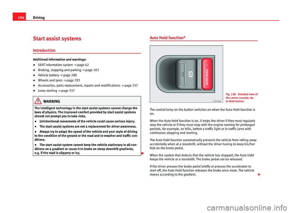
Fig. 138 Detailed view of
the centr
e c
onsole: Au-
to Hold button.
The control lamp on the button switches on when the Auto Hold function is
on.
When the Auto Hol
d function is on, it helps the driver if they must regularly
stop the vehicle or if they must stop with the engine running for prolonged
periods, for example, on hills, before a traffic light or in traffic jams with
continuous stopping and starting.
The Auto Hold function automatically prevents the vehicle from rolling away
accidentally when at a standstill, without the driver having to keep his/her
foot on the brake pedal.
When the system that detects that the vehicle has stopped, the Auto Hold
keeps the vehicle at a standstill. The brake pedal can be released.
If the driver presses the brake pedal briefly or presses the accelerator to
start off, the Auto Hold function releases the brake once more. The vehicle
moves according to the gradient.
Page 273 of 385
271
Checking and refilling levels
Selective Catalytic Reduction* (AdBlue)
Introduction The AdBlue fill level must be checked when the vehicle is being serviced
⇒ Bookl
et
Maintenance Programme.
Additional information and warnings:
● Luggage compartment ⇒ p
age 125
● Fuel ⇒ page 267
● Wheels
and tyres ⇒ pag
e 293
● Accessories, parts replacement, repairs and modifications ⇒ page 257WARNING
If the AdBlue fill level is too low, the vehicle may not restart after switch-
ing the ignition off .
The emergency start or jump start will not be possi-
ble either!
● Top up with AdBlue at the latest 1000 km or 600 miles before it runs
out.
● Do not a
llow the AdBlue to run too low. WARNING
AdBlue is an irritant, corrosive liquid that can cause injuries if it touches
the skin, ey e
s or respiratory organs.
● If AdBlue get in contact with eyes and skin, rinse for at least 15 mi-
nutes
with plenty of water and seek medical help.
● If the AdBlue is swallowed, wash the mouth with plenty of water for at
lea
st 15 minutes. Do not try to provoke vomiting unless recommended by
a Doctor. Seek medical advice immediately. CAUTION
AdBlue damages surfaces such as painted vehicle parts, plastic, items of
clothin g and c
arpets. Spilt AdBlue should be removed as quickly as possi-
ble using a damp cloth and plenty of cold water.
● If the AdBlue has crystallised, remove with warm water and a sponge.
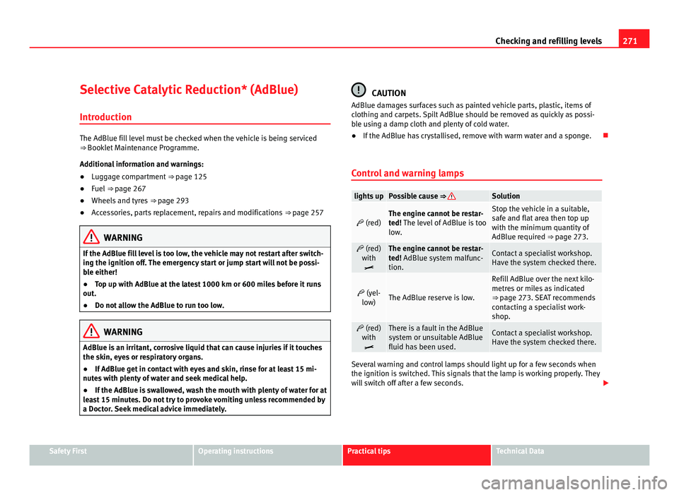
Control and warning lamps lights up Possible cause ⇒ Solution
(red) The engine cannot be restar-
ted!
The l
evel of AdBlue is too
low. Stop the vehicle in a suitable,
saf
e and fl
at area then top up
with the minimum quantity of
AdBlue required ⇒ page 273. (red)
with
The engine cannot be restar-
ted!
AdBlue sy
stem malfunc-
tion. Contact a specialist workshop.
Have the sy
s
tem checked there.
(yel-
lo w) The AdBlue reserve is low. Refill AdBlue over the next kilo-
metre
s
or miles as indicated
⇒ page 273. SEAT recommends
contacting a specialist work-
shop. (red)
with
There is a fault in the AdBlue
sys
t
em or unsuitable AdBlue
fluid has been used. Contact a specialist workshop.
Have the sy
s
tem checked there. Several warning and control lamps should light up for a few seconds when
the ignition is
sw
itched. This signals that the lamp is working properly. They
will switch off after a few seconds. Safety First Operating instructions Practical tips Technical Data
Page 339 of 385
337
If and when
Starting assistance
Introduction If the engine fails to start because of a discharged battery, the battery of an-
other v
ehic
le can be used to start the engine. Before starting, check the
magic eye on the battery ⇒ page 288.
For starting assistance, jump lead cables conforming to the standard
DIN 72553 are required (see the cable manufacturer instructions). The jump
lead cable must be at least 25 mm 2
in section (0.038 inches 2
) for petrol en-
gines, and 35 mm 2
(0.054 inches 2
) for diesel engines.
For vehicles whose battery is not in the engine compartment, the jump
leads should only be connected to the starting assistance connection
points in the engine compartment.
Additional information and warnings:
● Starter assist systems (Start-Stop function) ⇒ pag
e 194
● Working in the engine compartment ⇒ pag
e 275
● Selective Catalytic Reduction (AdBlue) ⇒ pag
e 271
● Vehicle battery ⇒ pag
e 288 WARNING
Incorrect use of jump leads and incorrectly jump starting could cause the
batt er
y to explode resulting in serious injury. Please observe the follow-
ing rules to minimise the risk of a battery explosion:
● All work involving the vehicle battery and electrical system can cause
corro
sion, fire and serious electric shocks. Always read and take into ac-
count the safety warnings and standards before beginning work on the
battery ⇒ page 288, Vehicle battery. WARNING (Continued)
● The b attery providing current must have the same voltage (12V) and
ap pr
oximately the same capacity (see markings on battery) as the flat
battery.
● Never charge a frozen or recently thawed battery. A flat battery can
freeze at
temperatures around 0°C (+32°F).
● If a battery is frozen and/or has been frozen then it must be replaced.
● A highly explosive mixture of gases is released when the battery is
being ch
arged. Always keep lit cigarettes, open flames, sparks and fire
far from the battery. Never use a mobile telephone when connecting and
removing the jump leads.
● Charge the battery only in well ventilated areas given that when the
batter
y is charged by outside assistance, it creates a mix of highly explo-
sive gases.
● Jump leads should never enter into contact with moving parts in the
engine comp
artment.
● Never switch the positive and negative poles or connect the jump
lea
ds incorrectly.
● Note the instructions provided by the manufacturer of the jump leads. CAUTION
To avoid considerable damage to the vehicle electrical system, note the fol-
low in
g carefully:
● If the jump leads are incorrectly connected, this could result in a short
circ
uit.
● The vehicles must not touch each other, otherwise electricity could flow
as soon a
s the positive terminals are connected. Safety First Operating instructions Practical tips Technical Data
Page 340 of 385
338
If and when
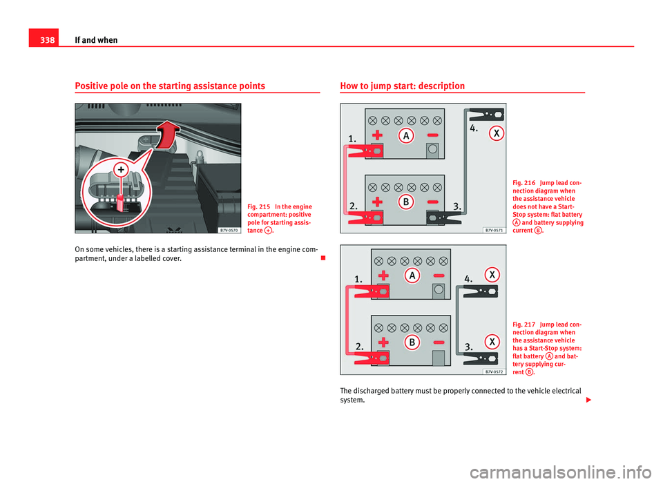
Positive pole on the starting assistance points Fig. 215 In the engine
comp
ar
tment: positive
pole for starting assis-
tance + .
On some vehicles, there is a starting assistance terminal in the engine com-
par tment, u
nder a labelled cover. How to jump start: description Fig. 216 Jump lead con-
nection diagr
am when
the a
ssistance vehicle
does not have a Start-
Stop system: flat battery A and battery supplying
curr ent
B .
Fig. 217 Jump lead con-
nection diagr
am when
the a
ssistance vehicle
has a Start-Stop system:
flat battery A and bat-
ter y
supplying cur-
rent B .
The discharged battery must be properly connected to the vehicle electrical
sys t
em.
Page 341 of 385
339
If and when
The vehicles should not touch. Otherwise, current may be allowed to flow
when the pos itiv
e poles are connected.
Connect the clamps so they have good metal-to-metal contact with the ter-
minals.
If the engine fails to start straight-away, switch off the starter after about 10
seconds and try again after about a minute.
Complete operations only in the sequence given.
Jump lead terminal connections
● Switch off the ignition of both vehicles ⇒ page 170.
● Lik
ewise, open the battery cover in the engine compartment
⇒ pag
e 288, or remove the positive pole cap from one side 1)
, in the direc-
tion of the arrow ⇒ fig. 215.
● Connect one end of the red
jump lead to the positive terminal
⇒ fig. 216 + or ⇒
fig. 215 + of the vehicle with the flat battery
A ⇒ .
● Connect the other end of the red
jump lead to the positive terminal + in
the v ehic
le providing assistance B .
● For vehicles without
Start-Stop system: Connect one end of the black
jump lead to the negative terminal - in the vehicle providing assistance
B ⇒ fig. 216.
● For vehicles with St
art-Stop system: Connect one end of the black X jump lead to a suitable ground connection, a solid piece of metal in the en-
gine bloc
k, or t
o the engine block ⇒ fig. 217.
● Connect the other end of the black
jump lead X to a solid metal compo-
nent c onnect
ed to the engine block, or onto the engine block itself of the
vehicle with the flat battery however, connect it as far away as possible from
the battery A ⇒ .
● Place the leads so that they cannot be caught by any moving parts in the
engine c omp
artment. Switching on
●
Start the engine of the vehicle supplying current and let it run at idling
speed.
● Star
t the engine of the car with the flat battery and wait two or three mi-
nutes
until the engine is “running smoothly”.
Removing the jump leads
● Before you remove the jump leads, switch off the headlights (if they are
switc
hed on).
● Turn on the heating and rear window heater in the vehicle with the flat
batter
y. This helps minimise voltage peaks which are generated when the
leads are disconnected.
● With the engines running, disconnect the leads in reverse order to con-
nection.
● Close the battery cover, or replace the positive pole cap 1)
. WARNING
Incorrectly jump starting could cause the battery to explode resulting in
serious injur
y. Please observe the following rules to minimise the risk of
a battery explosion:
● All work involving the vehicle battery and electrical system can cause
corro
sion, fire and serious electric shocks. Always read and take into ac-
count the safety warnings and standards before beginning work on the
battery ⇒ page 288, Vehicle battery.
● Always protect your eyes with suitable working goggles and never
lean o
ver the vehicle battery.
● The jump leads must be connected in the correct order: first the posi-
tive cab
le, then the negative cable. 1)
Vehicles whose battery is not located in the engine compartment ⇒ page 338. Safety First Operating instructions Practical tips Technical Data
Page 343 of 385
341
If and when
Instructions for tow starting In general, the vehicle should not be started by towing. Jump-starting is
much mor
e pr
eferable ⇒ page 337.
For technical reasons, the following vehicles can not be tow started:
● Vehicles with an automatic gearbox.
● Vehicles with an electronic parking brake, given that it is possible that
the brake w
ill not be disengaged.
● If the vehicle battery is flat, it is possible that the engine control units do
not operat
e correctly.
However, if your vehicle must absolutely be tow-started (manual gearbox):
● Engage the 2nd or 3rd gear.
● Keep the clutch pressed down.
● Switch on the ignition and the hazard warning lights.
● Release the clutch when both vehicles are moving.
● As soon as the engine starts, press the clutch and move the gear lever
into neutral
. This helps to prevent a collision with the towing vehicle. CAUTION
When tow-starting, fuel could enter the catalytic converter and damage it.
Towing instructions Tow-rope or tow-bar
When to
w
ing, the tow bar is the safest and vehicle friendly way. You should
only use a tow-rope if you do not have a tow-bar. A tow-rope should be slightly elastic to avoid damage to both vehicles. It is
advi
sable to use a tow-rope made of synthetic fibre or similarly elastic mate-
rial.
Only secure the tow rope or tow bar to the tow ring or specially designed
fitting.
Vehicles with a factory fitted towing device , can only be used for towing
with a tow-bar, specially designed to fit on a tow hitch ball ⇒ page 233.
Towing vehicles with an automatic gearbox
Note the following for a towed vehicle:
● Make sure the gear selector lever is in the N position.
● Do not
drive faster than 50 km/h (30 mph) when towing a vehicle.
● Do not tow further than 50 km (30 miles).
● If a breakdown truck is used, the vehicle must be towed with the front
wheels r
aised. Note the following instructions for towing four wheel drive
vehicles.
Instructions for towing four-wheel-drive vehicles
Four wheel drive vehicles can be towed using a toolbar or tow rope. If the
vehicle is towed with the front or rear axle raised, the engine must be turned
off to avoid transmission damage.
For vehicles with a double clutched DSG ®
(direct shift gearbox) the instruc-
tions for towing vehicles with an automatic gearbox apply ⇒ page 341.
Situations in which the vehicle should not be towed
In the following cases, the vehicle should not be towed but transported on a
trailer or special vehicle:
● If the vehicle gearbox does not contain lubricant due to a fault.
● If the vehicle battery is flat and, as a result, the electronic steering lock
and electronic
parking brake cannot be disengaged if applied.
● If the vehicle to be towed has an automatic gearbox and the distance to
be cov
ered is greater than 50 km (30 miles). Safety First Operating instructions Practical tips Technical Data
Page 344 of 385
342
If and when Note
The vehicle can only be towed if the electronic parking brake and steering
lock ar
e deactivated. If the vehicle has no power supply or there is an elec-
tric system fault, the engine must be started using jump leads to deactivate
the electronic parking brake and electronic steering lock.
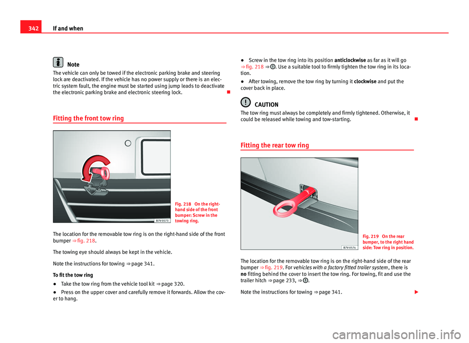
Fitting the front tow ring Fig. 218 On the right-
hand s
ide of
the front
bumper: Screw in the
towing ring.
The location for the removable tow ring is on the right-hand side of the front
bumper ⇒ fig. 218. The t
owing eye should always be kept in the vehicle.
Note the instructions for towing ⇒ page 341.
To fit the tow ring
● Take the tow ring from the vehicle tool kit ⇒ page 320.
● Pr
ess on the upper cover and carefully remove it forwards. Allow the cov-
er to han
g. ●
Screw in the tow ring into its position anticloc
kwise as far as it will go
⇒ fig. 218 ⇒ . Use a suitable tool to firmly tighten the tow ring in its loca-
tion.
● After towing, remove the tow ring by turning it clock
wise and put the
cover back in place. CAUTION
The tow ring must always be completely and firmly tightened. Otherwise, it
cou l
d be released while towing and tow-starting.
Fitting the rear tow ring Fig. 219 On the rear
bumper
, t
o the right hand
side: Tow ring in position.
The location for the removable tow ring is on the right-hand side of the rear
bumper ⇒ fig. 219. F
or vehicles with a factory fitted trailer system , there is
no fitting behind the cover to insert the tow ring. For towing, fit and use the
trailer hitch ⇒ page 233, ⇒ .
Note the in s
tructions for towing ⇒ page 341.
Page 379 of 385
Spare parts . . . . . . . . . . . . . . . . . . . . . . . . . . . . 257
Spec
i
al features
Automatic car wash . . . . . . . . . . . . . . . . . . 243
Folding exterior mirrors . . . . . . . . . . . . . . . 113
High pressure cleaning equipment . . . . . . 244
Parking . . . . . . . . . . . . . . . . . . . 183, 187, 363
Pushing . . . . . . . . . . . . . . . . . . . . . . . . . . . . 170
Radio reception . . . . . . . . . . . . . . . . . . . . . 255
Removing the vehicle key . . . . . . . . . . . . . 172
Washing the vehicle . . . . . . . . . . . . . . . . . . 243
Windscreen wipers . . . . . . . . . . . . . . . . . . . 106
Special notes High-pressure cleaning system . . . . . . . . . 235
Long parking times . . . . . . . . . . . . . . . . . . . 74
Towing . . . . . . . . . . . . . . . . . . . . . . . . . 340, 341
Tow starting . . . . . . . . . . . . . . . . . . . . . . . . 341
Specifications Combined weight . . . . . . . . . . . . . . . . . . . . 240
Drawbar load . . . . . . . . . . . . . . . . . . . . . . . 231
Trailer weight . . . . . . . . . . . . . . . . . . . . . . . 240
Specific notes Electric sliding doors . . . . . . . . . . . . . . . . . . 82
Spectacle case . . . . . . . . . . . . . . . . . . . . . . . . . 142
Speed rating . . . . . . . . . . . . . . . . . . . . . . . . . . . 303
Stabilising the vehicle and trailer combina- tion . . . . . . . . . . . . . . . . . . . . . . . . . . . . . . . . . 238
Start-Stop function Driving with a trailer . . . . . . . . . . . . . . . . . . 231
Start-Stop Function . . . . . . . . . . . . . . . . . . . . . 196
Start assist See "Start assist systems" . . . . . . . . . . . . . 194 Starting assistance . . . . . . . . . . . . . . . . . . . . . 337
Des cription . . . . . . . . . . . . . . . . . . . . . . . . . 338
Jump leads . . . . . . . . . . . . . . . . . . . . . . . . . 338
Positive pole on the starting assistance points . . . . . . . . . . . . . . . . . . . . . . . . . . . . 338
Starting using an external battery See Starting assistance . . . . . . . . . . . . . . . 337
Steering Control lamp . . . . . . . . . . . . . . . . . . . . . . . . 167
Counter steering assistance system . . . . . 168
Electromechanical . . . . . . . . . . . . . . . . . . . 168
Power steering . . . . . . . . . . . . . . . . . . . . . . 168
Steering column lock . . . . . . . . . . . . . . . . . 168
Tendency to pull to one side . . . . . . . . . . . 299
Warning lamp . . . . . . . . . . . . . . . . . . . . . . . 167
Steering wheel Adjustment . . . . . . . . . . . . . . . . . . . . . . . . . 169
Rocker switches (Tiptronic) . . . . . . . . . . . . 180
Storage compartments . . . . . . . . . . . . . . . . . . 141 Glove compartment lighting . . . . . . . . . . . 102
Sudden braking . . . . . . . . . . . . . . . . . . . . . . . . 313
Sun blind . . . . . . . . . . . . . . . . . . . . . . . . . . . . . 103
Sun blinds Rear side windows . . . . . . . . . . . . . . . . . . . 104
Sunshade Anti-trap function . . . . . . . . . . . . . . . . . . . . . 94
Closing . . . . . . . . . . . . . . . . . . . . . . . . . . . . . 93
Opening . . . . . . . . . . . . . . . . . . . . . . . . . . . . 93
Sun visor . . . . . . . . . . . . . . . . . . . . . . . . . . . . . . 103
Symbols See "Lamps" . . . . . . . . . . . . . . . . . . . . . . . . . 54
System Automatic dipped beam control . . . . . . . . . 99 Systems
ABS . . . . . . . . . . . . . . . . . . . . . . . . . . . . . . . 189
Ad
aptive headlights . . . . . . . . . . . . . . . . . . . 99
Anti-lock brake system (ABS) . . . . . . . . . . 189
ASR . . . . . . . . . . . . . . . . . . . . . . . . . . . . . . . 190
Auto Hold . . . . . . . . . . . . . . . . . . . . . . . . . . 194
BAS . . . . . . . . . . . . . . . . . . . . . . . . . . . . . . . 190
Braking assist . . . . . . . . . . . . . . . . . . . . . . . 190
Braking assist system (BAS) . . . . . . . . . . . 190
Cruise control . . . . . . . . . . . . . . . . . . . . . . . 212
EDS . . . . . . . . . . . . . . . . . . . . . . . . . . . . . . . 190
Electronic differential lock system (EDS) . 190
Electronic stability programme ESC (ESP) 189
ESC (ESP) . . . . . . . . . . . . . . . . . . . . . . . . . . 189
Lane Assist . . . . . . . . . . . . . . . . . . . . . . . . . 215
Lane Assist system . . . . . . . . . . . . . . . . . . . 215
Launch-Control Programme . . . . . . . . . . . . 181
Optical parking system . . . . . . . . . . . . . . . 200
Park assist . . . . . . . . . . . . . . . . . . . . . . . . . 199
Park Assist . . . . . . . . . . . . . . . . . . . . . . . . . 202
Park Assist system . . . . . . . . . . . . . . . . . . . 202
Parking sensor system . . . . . . . . . . . . . . . . 199
Rear Assist . . . . . . . . . . . . . . . . . . . . . . . . . 207
Rear assist system . . . . . . . . . . . . . . . . . . . 207
Sign Assist . . . . . . . . . . . . . . . . . . . . . . . . . 218
Start-Stop . . . . . . . . . . . . . . . . . . . . . . . . . . 196
Start assist . . . . . . . . . . . . . . . . . . . . . . . . . 194
TCS . . . . . . . . . . . . . . . . . . . . . . . . . . . . . . . 191
Traction control system . . . . . . . . . . . . . . . 191
Traction control when accelerating ASR (TCS) . . . . . . . . . . . . . . . . . . . . . . . . . . . . . 190
Tyre monitoring indicator . . . . . . . . . . . . . . 223
Tyre monitoring systems . . . . . . . . . . . . . . 221 377
Index