technical specifications Seat Alhambra 2015 Owner's Manual
[x] Cancel search | Manufacturer: SEAT, Model Year: 2015, Model line: Alhambra, Model: Seat Alhambra 2015Pages: 305, PDF Size: 5.46 MB
Page 261 of 305
Emergencies
● The brake must be depressed must harder
as the brake servo does not operate. Avoid
hitting the towing vehicle.
● Note the instructions and information con-
tained in the Instruction Manual for the vehi-
cle to be towed.
Notes for the driver of the towing vehicle
● Accelerate gently and carefully. Avoid sud-
den manoeuvres.
● Brake well in advance than usual and brake
gently.
● Note the instructions and information con-
tained in the Instruction Manual for the vehi-
cle to be towed.
Emergency locking and
unlocking
Introduction The doors, rear lid and panoramic sliding
sunroof can be locked manually and partially
opened, for example if the key or the central
locking is damaged.
WARNING
Opening and closing doors carelessly can
cause serious injury. ●
If the vehicle is locked from outside, the
doors and windows cannot be opened from
the inside.
● Never leave children or disabled people
alone in the car. They could be trapped in the
car in an emergency and will not be able to
get themselves to safety.
● Depending on the time of the year, temper-
atures inside a locked and closed vehicle can
be extremely high or extremely low resulting
in serious injuries and illness or even death,
particularly for young children. WARNING
Getting in the way of the doors and the pan-
oramic sliding sunroof is dangerous and can
lead to serious injury.
● Open and close the doors and the panor-
amic sliding sunroof only when nobody is in
the way. CAUTION
When opening and closing in an emergency,
carefully disassemble components and then
reassemble them carefully to avoid damage
to the vehicle. Manually locking and unlocking the
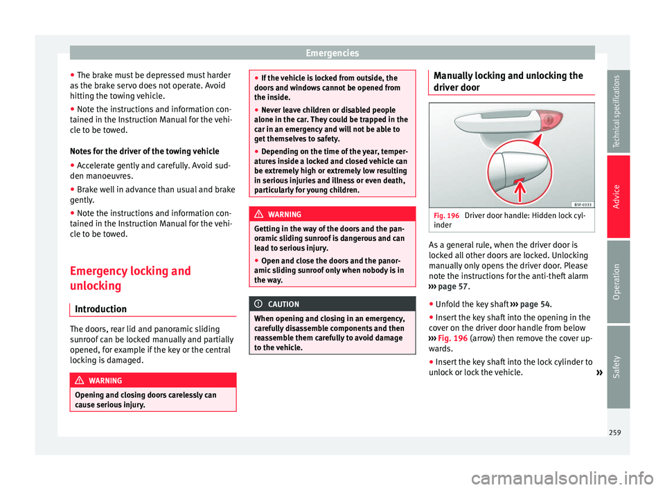
driver door
Fig. 196
Driver door handle: Hidden lock cyl-
inder As a general rule, when the driver door is
locked all other doors are locked. Unlocking
manually only opens the driver door. Please
note the instructions for the anti-theft alarm
››› page 57 .
● Unf o
ld the key shaft ››› page 54.
● Insert the key shaft into the opening in the
cover on the driver door handle from below
››› Fig. 196 (arrow) then remove the cover up-
war
ds.
● Insert the key shaft into the lock cylinder to
unlock or lock the vehicle. »
259
Technical specifications
Advice
Operation
Safety
Page 263 of 305
Emergencies
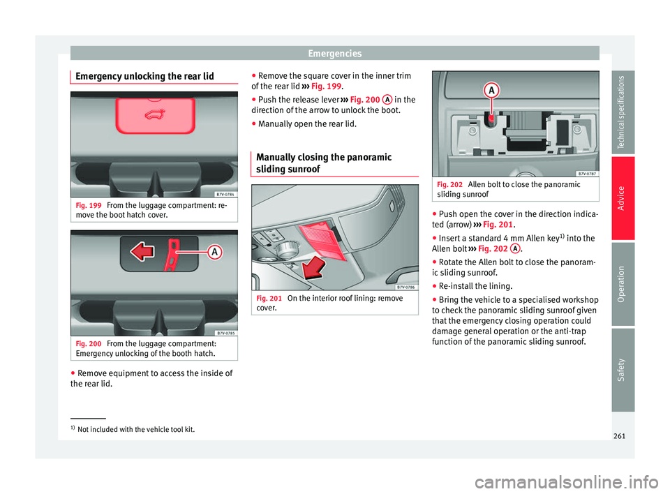
Emergency unlocking the rear lid Fig. 199
From the luggage compartment: re-
move the boot hatch cover. Fig. 200
From the luggage compartment:
Emergency unlocking of the booth hatch. ●
Remove equipment to access the inside of
the rear lid. ●
Remove the square cover in the inner trim
of the rear lid ››› Fig. 199.
● Push the release lever ››› Fig. 200 A in the
direction of the arrow to unlock the boot.
● Manually open the rear lid.
Manually closing the panoramic
sliding sunroof Fig. 201
On the interior roof lining: remove
cover. Fig. 202
Allen bolt to close the panoramic
sliding sunroof ●
Push open the cover in the direction indica-
ted (arrow) ››› Fig. 201.
● Insert a standard 4 mm Allen key 1)
into the
Allen bolt ››› Fig. 202 A .
● Rotate the Allen bolt to close the panoram-
ic sliding sunroof.
● Re-install the lining.
● Bring the vehicle to a specialised workshop
to check the panoramic sliding sunroof given
that the emergency closing operation could
damage general operation or the anti-trap
function of the panoramic sliding sunroof. 1)
Not included with the vehicle tool kit.
261Technical specifications
Advice
Operation
Safety
Page 265 of 305
Emergencies
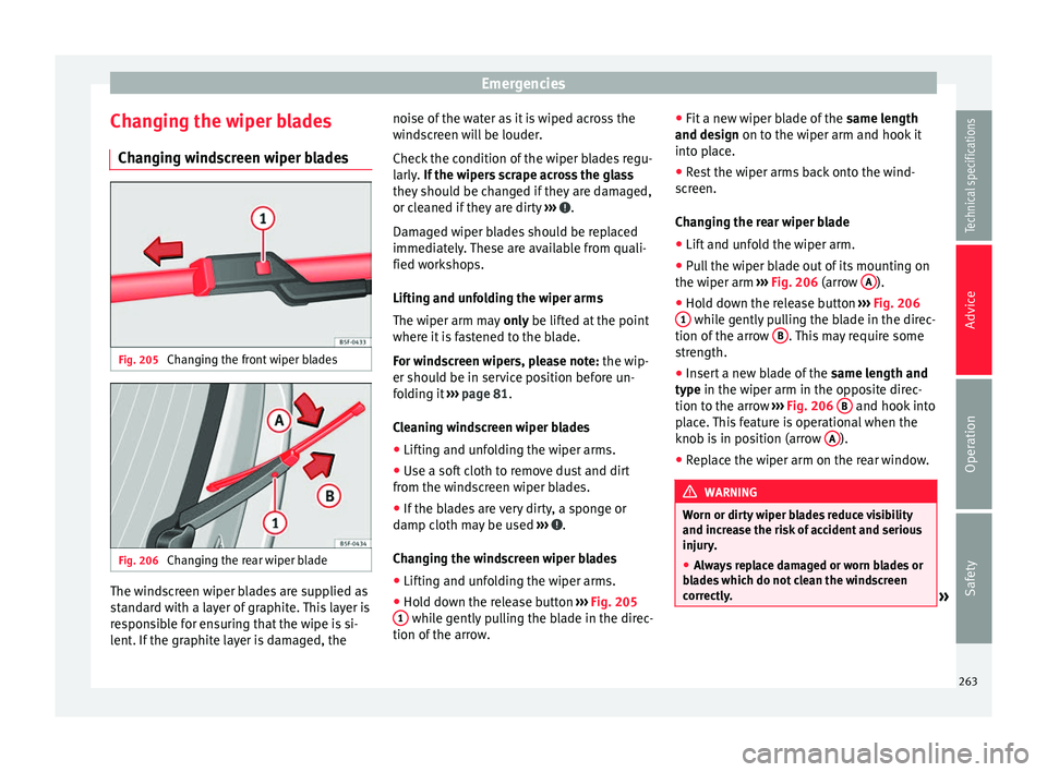
Changing the wiper blades Changing windscreen wiper blades Fig. 205
Changing the front wiper blades Fig. 206
Changing the rear wiper blade The windscreen wiper blades are supplied as
standard with a layer of graphite. This layer is
responsible for ensuring that the wipe is si-
lent. If the graphite layer is damaged, the noise of the water as it is wiped across the
windscreen will be louder.
Check the condition of the wiper blades regu-
larly.
If the wipers scrape across the glass
they shou
ld be changed if they are damaged,
or cleaned if they are dirty ››› .
Damaged wiper blades should be replaced
immediately. These are available from quali-
fied workshops.
Lifting and unfolding the wiper arms
The wiper arm may only be lifted at the point
wher e it
is fastened to the blade.
For windscreen wipers, please note: the wip-
er should be in service position before un-
folding it ››› page 81.
Cl
eaning windscreen wiper blades
● Lifting and unfolding the wiper arms.
● Use a soft cloth to remove dust and dirt
from the windscreen wiper blades.
● If the blades are very dirty, a sponge or
damp cloth may be used ››› .
Changing the windscreen wiper blades
● Lifting and unfolding the wiper arms.
● Hold down the release button ››› Fig. 205
1 while gently pulling the blade in the direc-
tion of the arrow. ●
Fit a new wiper blade of the same length
and design on to the wiper arm and hook it
int o p
lace.
● Rest the wiper arms back onto the wind-
screen.
Changing the rear wiper blade
● Lift and unfold the wiper arm.
● Pull the wiper blade out of its mounting on
the wiper arm ››› Fig. 206 (arrow A ).
● Hold down the release button ››› Fig. 206
1 while gently pulling the blade in the direc-
tion of the arrow B . This may require some
strength.
● Insert a new blade of the same length and
type in the wiper arm in the opposite direc-
tion t o the arr
ow ››› Fig. 206 B and hook into
place. This feature is operational when the
knob is in position (arrow A ).
● Replace the wiper arm on the rear window. WARNING
Worn or dirty wiper blades reduce visibility
and increase the risk of accident and serious
injury.
● Always replace damaged or worn blades or
blades which do not clean the windscreen
correctly. » 263
Technical specifications
Advice
Operation
Safety
Page 267 of 305
Fuses and bulbs
●
Several components may run on a single
fuse. Vehicle fuses
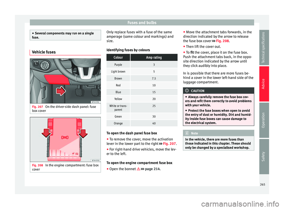
Fig. 207
On the driver-side dash panel: fuse
box cover Fig. 208
In the engine compartment: fuse box
cover Only replace fuses with a fuse of the same
amperage (same colour and markings) and
size.
Identifying fuses by coloursColourAmp rating
Purple3
Light brown5
Brown7.5
Red10
Blue15
Yellow20
White or trans-
parent25
Green30
Orange40 To open the dash panel fuse box
●
To remove the cover, move the activation
lever in the lower part to the right ››› Fig. 207.
● For right-hand drive vehicles, move the lev-
er to the left.
To open the engine compartment fuse box
● Open the bonnet ››› page 214. ●
Move the attachment tabs forwards, in the
direction indicated by the arrow to release
the fuse box cover ››› Fig. 208 .
● Then lif t
the cover out.
● To
fit the cover, place it on the fuse box.
Push the attachment tabs back, in the oppo-
site direction indicated by the arrow until
they click audibly into place.
In is possible that there are more fuses be-
hind a cover in the lower left-hand side of the
luggage compartment. CAUTION
● Always carefully remove the fuse box cov-
ers and refit them correctly to avoid problems
with your vehicle.
● Protect the fuse boxes when open to avoid
the entry of dust or humidity. Dirt and humid-
ity inside fuse boxes can cause damage to
the electrical system. Note
In the vehicle, there are more fuses than
those indicated in this chapter. These should
only be changed by a specialised workshop. 265
Technical specifications
Advice
Operation
Safety
Page 268 of 305
Advice
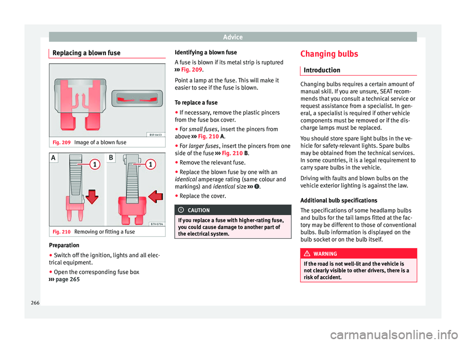
Replacing a blown fuse Fig. 209
Image of a blown fuse Fig. 210
Removing or fitting a fuse Preparation
● Switch off the ignition, lights and all elec-
trical equipment.
● Open the corresponding fuse box
››› page 265 Identifying a blown fuse
A fuse is blown if its metal strip is ruptured
››› Fig. 209 .
P oint
a lamp at the fuse. This will make it
easier to see if the fuse is blown.
To replace a fuse
● If necessary, remove the plastic pincers
from the fuse box cover.
● For
small fuses, insert the pincers from
above ››› Fig. 210 A.
● For
larger fuses , insert the pincers from one
side of the fuse ››› Fig. 210 B.
● Remove the relevant fuse.
● Replace the blown fuse by one with an
identical amperage rating (same colour and
mark
ings) and identical size ››› .
● Replace the cover. CAUTION
If you replace a fuse with higher-rating fuse,
you could cause damage to another part of
the electrical system. Changing bulbs
Introduction Changing bulbs requires a certain amount of
manual skill. If you are unsure, SEAT recom-
mends that you consult a technical service or
request assistance from a specialist. In gen-
eral, a specialist is required if other vehicle
components must be removed or if the dis-
charge lamps must be replaced.
You should store spare light bulbs in the ve-
hicle for safety-relevant lights. Spare bulbs
may be obtained from the technical services.
In some countries, it is a legal requirement to
carry spare bulbs in the vehicle.
Driving with faults and blown bulbs on the
vehicle exterior lighting is against the law.
Additional bulb specifications
The specifications of some headlamp bulbs
and bulbs for the tail lamps fitted at the fac-
tory may be different to those of conventional
bulbs. Bulb information is displayed on the
bulb socket or on the bulb itself.
WARNING
If the road is not well-lit and the vehicle is
not clearly visible to other drivers, there is a
risk of accident. 266
Page 269 of 305
Fuses and bulbs
WARNING
Failure to replace bulbs correctly may cause
serious accidents.
● Before carrying out any work in the engine
compartment please read and observe the
warnings ››› page 214. In any vehicle, the en-
gine c omp
artment is a hazardous area and
could cause severe injury.
● Discharge lamps work with high-voltage
and can cause serious or fatal injury if han-
dled incorrectly.
● H7 and discharge lamps are highly pressur-
ised and could explode when being changed.
● Only replace the bulbs concerned when
they have cooled.
● Never replace bulbs alone if you are not fa-
miliar with the operations necessary. If you
are not sure about procedures then visit a
specialised workshop to carry out the neces-
sary work.
● Never touch the bulb glass directly. Finger-
prints will be evaporated by the heat of the
operating bulb thus “fogging” up the reflec-
tor.
● The headlamp frameworks in the engine
compartment and the tail lamps contain sharp elements. Always protect your hands
when changing bulbs.
CAUTION
● After changing a bulb, if the rubber covers
are not replaced correctly on the headlamp
framework, the electrical installation may be
damaged, especially if water is allowed to en-
ter.
● Remove the ignition key before working on
the electric system. Otherwise, a short circuit
could occur.
● Switch off the lights and the parking light
before changing a bulb.
● Take good care to avoid damaging any com-
ponents. Control lamp
It
lights upPossible causeSolution
A vehicle exterior
lighting bulb is not
working.Replace the faulty
bulb. Several warning and control lamps light up
for a few seconds when the ignition is switch-
ed on, signalling that the function is being
verified. They will switch off after a few sec-
onds.
Checking the bulbs of a trailer
For vehicles with the factory fitted towing
bracket, certain trailer lights are also control-
led if the power socket is correctly connected.
A fault on a trailer turn signal is indicated on
the instrument panel by the turn signal blink-
ing twice as fast (
or ) ››› page 74.
● General fault of all turn signals on one side.
● Fault in one tail light (on some models, al-
so the registration light).
● Fault in two brake lights. WARNING
Observe the safety warnings ››› in Control
and warning lamps on page 47. Note
A fault in the LED on the tail lights will not be
indicated. However, if the fault affects all the
LEDs then this will be indicated by the control
lamp . 267
Technical specifications
Advice
Operation
Safety
Page 271 of 305
Fuses and bulbs
ABC
Turn signals (small lamp holder)Dipped beam
headlightsDaytime driving lightMain beam headlightsSide lights
6.Place the bulb holder in the headlight and rotate to the right all the way.Place the lamp holder in the head-
light and pull the wire clip upwards until it clicks into place.Place the lamp holder in the head-light and insert completely.
7. Insert the rubber cover. Note
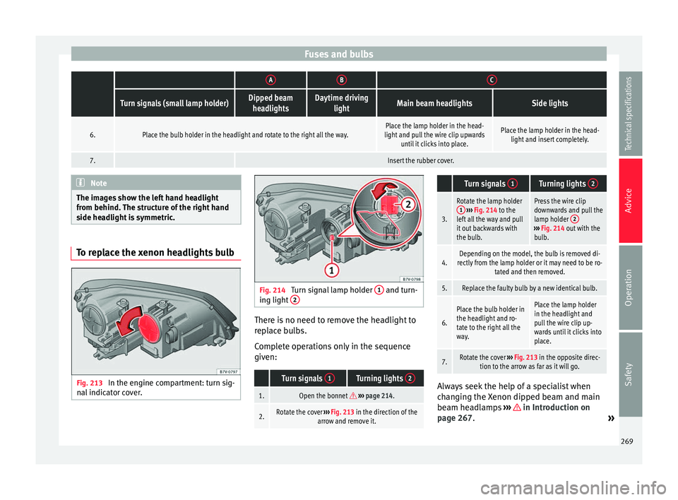
The images show the left hand headlight
from behind. The structure of the right hand
side headlight is symmetric. To replace the xenon headlights bulb
Fig. 213
In the engine compartment: turn sig-
nal indicator cover. Fig. 214
Turn signal lamp holder 1 and turn-
ing light 2 There is no need to remove the headlight to
replace bulbs.
Complete operations only in the sequence
given:
Turn signals
1Turning lights 2
1.Open the bonnet
››› page 214.
2.Rotate the cover ››› Fig. 213 in the direction of the
arrow and remove it.
Turn signals 1Turning lights 2
3.
Rotate the lamp holder
1 ››› Fig. 214 to the
left all the way and pull
it out backwards with
the bulb.Press the wire clip
downwards and pull the
lamp holder 2
›››
Fig. 214 out with the
bulb.
4.Depending on the model, the bulb is removed di-
rectly from the lamp holder or it may need to be ro- tated and then removed.
5.Replace the faulty bulb by a new identical bulb.
6.
Place the bulb holder in
the headlight and ro-
tate to the right all the
way.Place the lamp holder
in the headlight and
pull the wire clip up-
wards until it clicks into
place.
7.Rotate the cover ››› Fig. 213 in the opposite direc-
tion to the arrow as far as it will go. Always seek the help of a specialist when
changing the Xenon dipped beam and main
beam headlamps
››› in Introduction on
page 267. »
269
Technical specifications
Advice
Operation
Safety
Page 273 of 305
Fuses and bulbs
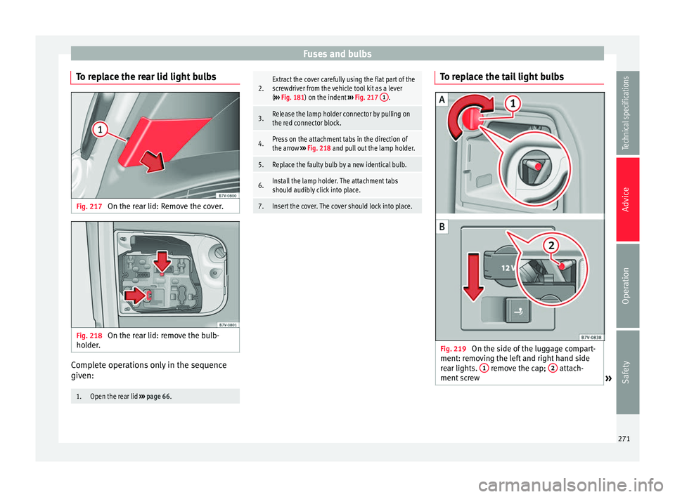
To replace the rear lid light bulbs Fig. 217
On the rear lid: Remove the cover. Fig. 218
On the rear lid: remove the bulb-
holder. Complete operations only in the sequence
given:1.Open the rear lid
››› page 66.
2.Extract the cover carefully using the flat part of the
screwdriver from the vehicle tool kit as a lever
(››› Fig. 181) on the indent ››› Fig. 217 1
.
3.Release the lamp holder connector by pulling on
the red connector block.
4.Press on the attachment tabs in the direction of
the arrow
››› Fig. 218 and pull out the lamp holder.
5.Replace the faulty bulb by a new identical bulb.
6.Install the lamp holder. The attachment tabs
should audibly click into place.
7.Insert the cover. The cover should lock into place. To replace the tail light bulbs
Fig. 219
On the side of the luggage compart-
ment: removing the left and right hand side
rear lights. 1 remove the cap;
2 attach-
ment screw » 271
Technical specifications
Advice
Operation
Safety
Page 275 of 305
Fuses and bulbs
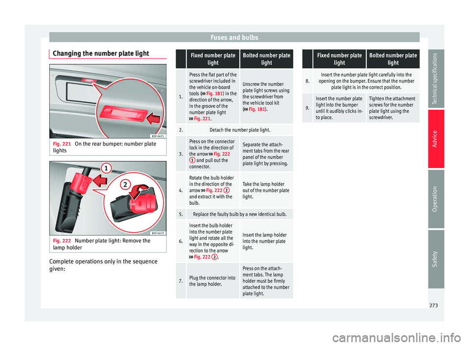
Changing the number plate light Fig. 221
On the rear bumper: number plate
lights Fig. 222
Number plate light: Remove the
lamp holder Complete operations only in the sequence
given: Fixed number plate
lightBolted number plate light
1.
Press the flat part of the
screwdriver included in
the vehicle on-board
tools (››› Fig. 181) in the
direction of the arrow,
in the groove of the
number plate light
››› Fig. 221.
Unscrew the number
plate light screws using
the screwdriver from
the vehicle tool kit
(››› Fig. 181).
2.Detach the number plate light.
3.
Press on the connector
lock in the direction of
the arrow ››› Fig. 222
1
and pull out the
connector.
Separate the attach-
ment tabs from the rear
panel of the number
plate light by pressing.
4.
Rotate the bulb holder
in the direction of the
arrow ››› Fig. 222 2
and extract it with the
bulb.
Take the lamp holder
out of the number plate
light.
5.Replace the faulty bulb by a new identical bulb.
6.
Insert the bulb holder
into the number plate
light and rotate all the
way in the opposite di-
rection to the arrow
››› Fig. 222 2
.
Insert the lamp holder
into the number plate
light.
7.Plug the connector into
the lamp holder.
Press on the attach-
ment tabs. The lamp
holder must be firmly
attached to the number
plate light.
Fixed number plate
lightBolted number plate light
8.Insert the number plate light carefully into the
opening on the bumper. Ensure that the number plate light is in the correct position.
9.
Insert the number plate
light into the bumper
until it audibly clicks in-
to place.Tighten the attachment
screws for the number
plate light using the
screwdriver. 273Technical specifications
Advice
Operation
Safety
Page 276 of 305
Technical specifications
Technical specifications
Technical specifications
Important information Important The information in the vehicle documentation
always takes precedence over the informa-
tion in this Instruction Manual.
All technical specifications provided in this
documentation are valid for the standard
model in Spain. The vehicle data card inclu-
ded in the Maintenance Programme or the
vehicle registration documents shows which
engine is installed in the vehicle.
The figures may be different depending
whether additional equipment is fitted, for
different models, for special vehicles and for
other countries.
Abbreviations used in the Technical
Specifications sectionAbbrevi-
ationMeaning
kWKilowatt, engine power measurement.
PSPferdestärke (horsepower), formerly used
to denote engine power.
rpmRevolutions per minute - engine speed.
NmNewton metres, unit of engine torque.
litres per100 kmFuel consumption in litres per 100 km (70
miles).
g/kmCarbon dioxide emissions in grams per km
(mile) travelled.
CO 2Carbon dioxide
CNCetane number, indication of the diesel
combustion power.
RONResearch octane number, indication of the
knock resistance of petrol. Vehicle code
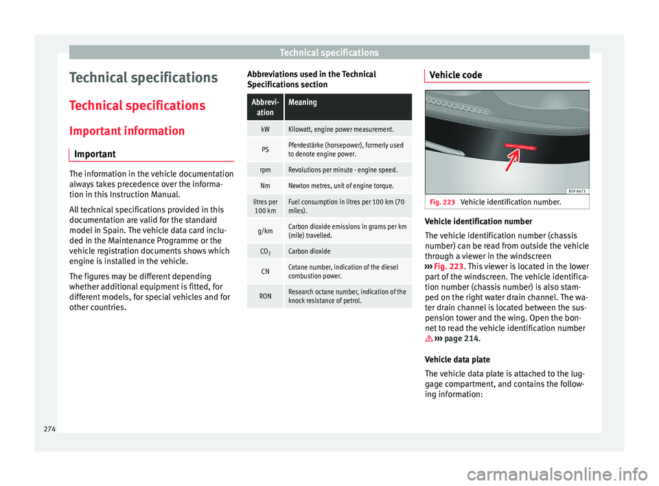
Fig. 223
Vehicle identification number. Vehicle identification number
The vehicle identification number (chassis
number) can be read from outside the vehicle
through a viewer in the windscreen
››› Fig. 223 . This viewer is located in the lower
p ar
t of the windscreen. The vehicle identifica-
tion number (chassis number) is also stam-
ped on the right water drain channel. The wa-
ter drain channel is located between the sus-
pension tower and the wing. Open the bon-
net to read the vehicle identification number
››› page 214.
Vehic
le data plate
The vehicle data plate is attached to the lug-
gage compartment, and contains the follow-
ing information:
274