clock Seat Alhambra 2015 Owner's Manual
[x] Cancel search | Manufacturer: SEAT, Model Year: 2015, Model line: Alhambra, Model: Seat Alhambra 2015Pages: 305, PDF Size: 5.46 MB
Page 9 of 305
Safe driving
If your physical constitution prevents you
from maintaining the correct sitting position,
contact a specialised workshop for help with
any special devices. The seat belt and airbag
can only provide optimum protection if a cor-
rect sitting position is adopted. SEAT recom-
mends taking your car in for technical serv-
ice.
For your own safety and to reduce the risk of
injury in the event of an accident or sudden
braking or manoeuvre, SEAT recommend the
following positions:
Valid for all vehicle occupants:
● Adjust the head restraint so that its upper
edge is at the same level as the top of your
head, or as close as possible to the same lev-
el as the top of your head and under no cir-
cumstances below eye level. Keep the back
of your neck as close as possible to the head
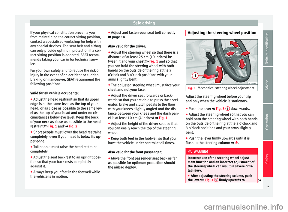
restraint ››› Fig. 1 and
›
›› Fig. 2.
● Short people must lower the head restraint
completely, even if your head is below its up-
per edge.
● Tall people must raise the head restraint
completely.
● Adjust the seat backrest to an upright posi-
tion so that your back rests completely
against it.
● Always keep your feet in the footwell while
the vehicle is in motion. ●
Adjust and fasten your seat belt correctly
››› page 14.
Al
so valid for the driver:
● Adjust the steering wheel so that there is a
distance of at least 25 cm (10 inches) be-
tween it and your chest ››› Fig. 1 and so that
you c
an hold the steering wheel with both
hands on the outside of the ring at the 9
o'clock and 3 o'clock positions with your
arms slightly bent.
● The adjusted steering wheel must face your
chest and not your face.
● Adjust the driver seat forwards or back-
wards so that you are able to press the accel-
erator, brake and clutch pedals to the floor
with your knees slightly angled and the dis-
tance between your knees and the dash pan-
el is at least 10 cm (4 inches) ››› Fig. 1
.
● Adjust the height of the driver seat so that
you can easily reach the top of the steering
wheel.
● Keep both feet in the footwell so that you
have the vehicle under control at all times.
Also valid for the front passenger:
● Move the front passenger seat back as far
as possible for optimum protection should
the airbag deploy. Adjusting the steering wheel position
Fig. 3
Mechanical steering wheel adjustment Adjust the steering wheel before your trip
and only when the vehicle is stationary.
●
Push the lever ››› Fig. 3 1 downwards.
● Adjust the steering wheel so that you can
hold onto the steering wheel with both hands
on the outside of the ring at the 9 o'clock and
3 o'clock positions and your arms slightly
bent.
● Push the lever firmly upwards until it is
flush to the steering column ››› .
WARNING
Incorrect use of the steering wheel adjust-
ment function and an incorrect adjustment of
the steering wheel can result in severe or fa-
tal injury.
● After adjusting the steering column, push
the lever ››› Fig. 3 1 firmly upwards to
» 7
Technical specifications
Advice
Operation
Safety
Page 10 of 305
Safety
ensure the steering wheel does not acciden-
tally change position while driving.
●
Never adjust the steering wheel while the
vehicle is in motion. If you need to adjust the
steering wheel while the vehicle is in motion,
stop safely and make the proper adjustment.
● The adjusted steering wheel should be fac-
ing your chest and not your face so as not to
hinder the driver's front airbag protection in
the event of an accident.
● When driving, always hold the steering
wheel with both hands on the outside of the
ring at the 9 o'clock and 3 o'clock positions
to reduce injuries when the driver's front air-
bag deploys.
● Never hold the steering wheel at the 12
o'clock position or in any other manner (e.g.
in the centre of the steering wheel). In such
cases, if the driver's airbag deploys, you may
sustain injuries to your arms, hands and
head. Danger of injuries due to an incorrect
sitting position
Number of seats
Depending on the equipment, your vehicle
has a total of
five or
seven seats. Each seat is
equipped with a seat belt.
EquipmentSeats in
the frontSeats in the sec-
ond rowSeats in
the third row
5 seats23–
7 seats232 If the seat belts are worn incorrectly or not at
all, the risk of severe injuries increases. Seat
belts can provide optimal protection only if
the belt web is properly worn. Being seated
in an incorrect position means the seat belt
cannot offer its full protection. This could re-
sult in severe and even fatal injuries. The risk
of severe or fatal injuries is especially height-
ened when a deploying airbag strikes a vehi-
cle occupant who has assumed an incorrect
sitting position. The driver is responsible for
all passengers in the vehicle, particularly
children.
The following list shows just some examples
of incorrect sitting positions which can be
dangerous to all vehicle occupants.
Whenever the vehicle is in motion:
●
Never stand in the vehicle.
● Never stand on the seats.
● Never kneel on the seats.
● Never tilt your seat backrest too far to the
rear.
● Never lean against the dash panel. ●
Never lie on the rear bench.
● Never sit on the front edge of a seat.
● Never sit sideways.
● Never lean out of a window.
● Never put your feet out of a window.
● Never put your feet on the dash panel.
● Never put your feet on the surface of a seat
or seat backrest.
● Never travel in a footwell.
● Never sit on the armrests.
● Never travel on a seat without wearing the
seat belt.
● Never carry any person in the luggage com-
partment. WARNING
An incorrect sitting position in the vehicle
can lead to severe injuries or death in the
event of sudden braking or manoeuvres, colli-
sion or accidents or if the airbag deploys.
● Before the vehicle moves, assume the prop-
er sitting position and maintain it throughout
the trip. This also includes fastening the seat
belt.
● Never transport more people than there are
seats with a seat belt available in the vehicle.
● Children must always be protected with an
approved child restraint system suited to
their height and weight ››› page 26,
››› page 20.8
Page 23 of 305
Airbag system
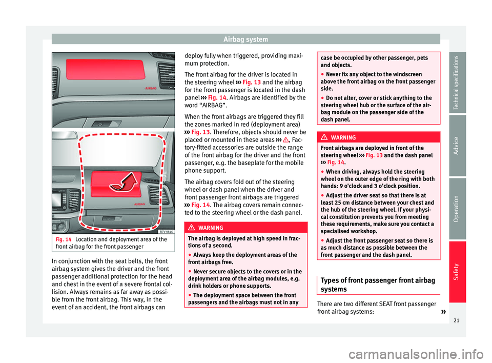
Fig. 14
Location and deployment area of the
front airbag for the front passenger In conjunction with the seat belts, the front
airbag system gives the driver and the front
passenger additional protection for the head
and chest in the event of a severe frontal col-
lision. Always remains as far away as possi-
ble from the front airbag. This way, in the
event of an accident, the front airbags can deploy fully when triggered, providing maxi-
mum protection.
The front airbag for the driver is located in
the steering wheel
››› Fig. 13 and the airbag
f or the fr
ont passenger is located in the dash
panel ››› Fig. 14. Airbags are identified by the
wor
d “AIRBAG”.
When the front airbags are triggered they fill
the zones marked in red (deployment area)
››› Fig. 13. Therefore, objects should never be
pl
aced or mounted in these areas ››› , Fac-
tory-fitted accessories are outside the range
of the front airbag for the driver and the front
passenger, e.g. the baseplate for the mobile
phone support.
The airbag covers fold out of the steering
wheel or dash panel when the driver and
front passenger front airbags are triggered
››› Fig. 14 . The airbag covers remain connec-
t ed t
o the steering wheel or the dash panel. WARNING
The airbag is deployed at high speed in frac-
tions of a second.
● Always keep the deployment areas of the
front airbags free.
● Never secure objects to the covers or in the
deployment area of the airbag modules, e.g.
drink holders or phone supports.
● The deployment space between the front
passengers and the airbags must not in any case be occupied by other passenger, pets
and objects.
●
Never fix any object to the windscreen
above the front airbag on the front passenger
side.
● Do not alter, cover or stick anything to the
steering wheel hub or the surface of the air-
bag module on the passenger side of the
dash panel. WARNING
Front airbags are deployed in front of the
steering wheel ››› Fig. 13
and the dash panel
› ›
› Fig. 14.
● When drivin
g, always hold the steering
wheel on the outer edge of the ring with both
hands: 9 o'clock and 3 o'clock position.
● Adjust the driver seat so that there is at
least 25 cm distance between your chest and
the hub of the steering wheel. If your physi-
cal constitution prevents you from meeting
these requirements, make sure you contact a
specialised workshop.
● Adjust the front passenger seat so there is
as much distance as possible between the
front passenger and the dash panel. Types of front passenger front airbag
systems
There are two different SEAT front passenger
front airbag systems:
»
21
Technical specifications
Advice
Operation
Safety
Page 43 of 305
Cockpit
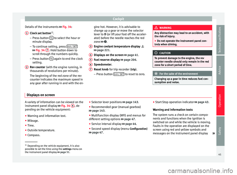
Details of the instruments ››› Fig. 34 :
C loc
k set button 1)
.
– Press button to select the hour or
minute display.
– To continue setting, press 0.0 / SET›››
Fig. 34 7 . Hold button down to
scroll through the numbers quickly.
– Press button again to end the clock
setting.
Rev counter (with the engine running, in
thousands of revolutions per minute).
The beginning of the red zone of the rev
counter indicates the maximum speed in
any gear after running-in and with the en-
1 2 gine hot. However, it is advisable to
change up a gear or move the selector
lever to
D
(or lift your foot off the acceler-
at
or) before the needle reaches the red
zone ››› .
Engine coolant temperature display
››› page 221 .
Di s
plays on the screen ››› page 41.
Fuel reserve display ››› page 206.
Speedometer.
Reset knob for trip recorder (trip).
– Pre
ss button 0.0 / SET to reset to zero.
3 4
5
6
7 WARNING
Any distraction may lead to an accident, with
the risk of injury.
● Do not operate the instrument panel con-
trols when driving. CAUTION
To prevent damage to the engine, the rev
counter needle should only remain in the red
zone for a short period of time. For the sake of the environment
Changing up a gear in time reduces fuel con-
sumption and noise. Displays on screen
A variety of information can be viewed on the
instrument panel display
››› Fig. 34 4 , de-
pending on the vehicle equipment:
● Warning and information text.
● Mileage.
● Time.
● Outside temperature.
● Compass. ●
Selector lever positions ››› page 143.
● Recommended gear (manual gearbox)
››› page 143 .
● Mu
ltifunction display (MFI) and menus for
different setting options ››› page 47.
● Service interval display ››› page 44 .
● Second speed display (menu Configuration)
››› page 47. ●
Star
t-Stop operation indicator
››› page 43.
Warning and information texts
The system runs a check on certain compo-
nents and functions when the ignition is
switched on and while the vehicle is moving.
Faults in the operation are displayed on the
screen using red and yellow symbols and
messages on the instrument panel display »1)
Depending on the vehicle equipment, it is also
possible to set the time using the settings menu on
the in s
trument panel display ››› page 51.
41
Technical specifications
Advice
Operation
Safety
Page 46 of 305
Operation
Service interval display The service indication is shown on the dash
panel display
››› Fig. 34 4 .
SEAT distinguishes between services with en-
gine oi l
change (Interval Service) and serv-
ices without
engine oil change (Inspection
Service). The service interval display only
gives information for service dates which in-
volve an engine oil change. The dates for the
other services (e.g. the next Inspection Serv-
ice or change of brake fluid) are listed on the
label attached to the door strut, or in the
Maintenance Programme.
In vehicles with Services established by time
or mileage, the service intervals are already
pr e-defined.
In
vehicles with LongLife Service , the inter-
vals are determined individually. Technical
progress has made it possible to considera-
bly reduce servicing requirements. The tech-
nology used by SEAT ensures that your vehi-
cle only has an Interval Service when it is
necessary. To establish when the Interval
Service is due (max. 2 years), the vehicle's
conditions of use and individual driving
styles are considered. The service pre-warn-
ing first appears 20 days before the date es-
tablished for the corresponding service. The
kilometres (miles) remaining until the next
service are always rounded up to the nearest
100 km (miles) and the time is given in com-
plete days. The current service message can- not be viewed until 500 km after the last
service. Prior to this only lines are visible on
the display.
Inspection reminder
When the Service date is approaching, when
the ignition is switched on a
Service remind-
er
is displayed.
In
vehicles without text messages , a spanner
is displayed on the instrument panel with
a figure given in km. The number of kilome- tre
s shown is the maximum number that may
be driven until the next service. After a few
seconds, the display mode changes. A clock
symbol appears and the number of days until
the next service appointment is due.
In vehicles with text messages , Serv
ice in ---
km (miles) or --- days is displayed on the in- strument panel.
Service due
After the service date, an audible warning is
giv
en when the ignition is switched on and
the spanner displayed on the screen flashes
for a few seconds . In
vehicles with text
messages, Service in --- km or --- days is dis-
played on the instrument panel.
Reading a service notification
With the ignition switched on, the engine off
and the vehicle at a standstill, the current
service notification
can be read: ●
Press the button on the instrument pan-
el several times until the spanner symbol is
displayed
.
● OR:
select the Setting
s menu.
● From the
Service submenu, select the op-
tion Info.
When the service date has past , a minus
sign
is displayed in front of the number of kilome-
tres or days. In vehicles with text messages
the following is displayed: Service --- km
(miles) or --- days ago .
Resetting service interval display
If the service was not carried out by a techni-
cal service centre, the display can be reset as
follows:
In vehicles with text messages:
Select the Settings menu.
In the submenu Service, select the option Reset.
Confirm with OK when requested to do so by the sys-
tem.
In vehicles without text messages:
Switch the ignition off.
Press and hold the 0.0 / SET button.
Switch the ignition back on.44
Page 53 of 305
CockpitMenuFunction
Speed warn-
ing at --- km/hIf the stored speed is exceeded (be-
tween 30 - 250 km/h, or 18 -
155 mph), an audible warning is given
together with a visual warning. Changing between display modes
● In vehicles without multifunction steering
wheel: press the lever.
● Vehicle
s with a multifunction steering
wheel:
press or
.
Storing a speed for the speed warning
● Select the display Speed warning at --- km/h
.
● Press OK to store the current speed and
switch off the warning.
● In addition, set the required speed by
pressing the rocker switch on the windscreen
wiper lever or buttons or
on the multi-
function steering wheel for 5 seconds. Next,
press OK again or wait a few seconds. The
speed is stored and the warning activated.
● To switch off , press OK . The stored speed is
deleted.
Manually erasing memory 1 or 2
● Select the memory to be erased.
● Press and hold OK for approximately 2 sec-
onds. Personalising the displays
It is possible to select which of the displays
in the multifunction display you wish to see
on the instrument panel in the
settings
menu. The units of measurement can also be
modified ››› page 51 .
C onfigur
ation Menu
Configu-
ration
MenuFunction
Multi-
function
display
dataConfiguration of the multifunction display
data that you wish to see on the instrument
panel display ››› page 50.
Compass
Changing the magnetic region and calibra-
tion of the compass. To calibrate the com-
pass, please follow the instructions given
on the instrument panel display.
Conven-
ienceChanging vehicle convenience functions
››› page 52.
Lights &
visibilityConfiguration of vehicle lighting
››› page 52.
Time
Changing the hours and minutes of the in-
strument panel clock and the navigation
system. The time can be set here and the
choice can be made between the 24-hour
and 12-hour display. The S in the upper
part of the display indicates that the clock
is set to summer time.
Configu-
ration
MenuFunction
Winter
tyres
Changing the visual and audible speed
warnings. This function should only be
used when the vehicle is fitted with winter
tyres, which are not designed for travel at
high speeds.
LanguageChanging the language of the display texts
and the navigation system.
UnitsChanging the units of measurement for the
temperature, consumption and distance.
Second
speedSwitching second speed display on and off.
Auto-HoldSelect if the Auto-Hold function should be
on permanently.
ServiceCheck the service notifications or reset the
service intervals to zero.
Factory
settingsSome functions of the Configuration menu
will be reset to the factory value.
BackThe main menu is displayed again. 51
Technical specifications
Advice
Operation
Safety
Page 119 of 305
Transport and practical equipment
Side compartments in the luggage
compartment
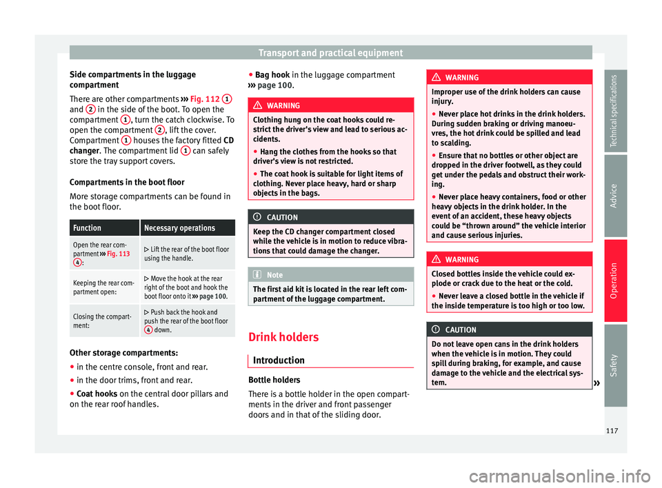
There are other compartments ››› Fig. 112 1 and
2 in the side of the boot. To open the
compartment 1 , turn the catch clockwise. To
open the compartment 2 , lift the cover.
Compartment 1 houses the factory fitted
CD
changer . The compartment lid 1 can safely
store the tray support covers.
Compartments in the boot floor
More storage compartments can be found in
the boot floor.FunctionNecessary operations
Open the rear com-
partment ››› Fig. 113
4
:
Lift the rear of the boot floor
using the handle.
Keeping the rear com-
partment open: Move the hook at the rear
right of the boot and hook the
boot floor onto it ››› page 100.
Closing the compart-
ment: Push back the hook and
push the rear of the boot floor 4
down. Other storage compartments:
● in the centre console, front and rear.
● in the door trims, front and rear.
● Coat hooks on the central door pillars and
on the rear roof handles. ●
Bag hook in the luggage compartment
› ›
› page 100. WARNING
Clothing hung on the coat hooks could re-
strict the driver's view and lead to serious ac-
cidents.
● Hang the clothes from the hooks so that
driver's view is not restricted.
● The coat hook is suitable for light items of
clothing. Never place heavy, hard or sharp
objects in the bags. CAUTION
Keep the CD changer compartment closed
while the vehicle is in motion to reduce vibra-
tions that could damage the changer. Note
The first aid kit is located in the rear left com-
partment of the luggage compartment. Drink holders
Introduction Bottle holders
There is a bottle holder in the open compart-
ments in the driver and front passenger
doors and in that of the sliding door. WARNING
Improper use of the drink holders can cause
injury.
● Never place hot drinks in the drink holders.
During sudden braking or driving manoeu-
vres, the hot drink could be spilled and lead
to scalding.
● Ensure that no bottles or other object are
dropped in the driver footwell, as they could
get under the pedals and obstruct their work-
ing.
● Never place heavy containers, food or other
heavy objects in the drink holder. In the
event of an accident, these heavy objects
could be “thrown around” the vehicle interior
and cause serious injuries. WARNING
Closed bottles inside the vehicle could ex-
plode or crack due to the heat or the cold.
● Never leave a closed bottle in the vehicle if
the inside temperature is too high or too low. CAUTION
Do not leave open cans in the drink holders
when the vehicle is in motion. They could
spill during braking, for example, and cause
damage to the vehicle and the electrical sys-
tem. » 117
Technical specifications
Advice
Operation
Safety
Page 211 of 305
Checking and refilling levels
● Unscrew the tank cap anticlockwise and in-
sert it in the hole in the tank flap hinge
››› Fig. 159 .
R ef
uelling
The correct petrol type for the vehicle is loca-
ted on a sticker inside the fuel tank flap
››› page 209.
● If the aut
omatic filler nozzle is operated
correctly, it will switch itself off as soon as
the tank is full ››› .
● Do not continue to refuel if it is turned off!
Otherwise, this will fill the expansion cham-
ber and fuel may leak out if the ambient con-
ditions are warm.
Closing the fuel tank cap
● Screw on the tank cap clockwise until it you
hear it click into position.
● Press the tank flap until you hear it click in-
to place. The tank flap must be flush with the
body contour. WARNING
Do not continue refilling once the fuel nozzle
has switched itself off. The fuel tank may be
filled too much. As a result, fuel may spurt
out and spill. This could lead to a fire, explo-
sion and severe injuries. CAUTION
● Always remove any fuel spilled on the vehi-
cle paintwork immediately to avoid damage
to the wheel housing, the tyre and vehicle
paintwork. For the sake of the environment
Spilt fuel can contaminate the environment. Fuel
Introduction You will find a factory-fitted sticker containing
information on the type of fuel for your vehi-
cle on the inside of the fuel tank flap.
WARNING
Refuelling or handling fuel carelessly can
cause an explosion or fire resulting in serious
burns and injuries.
● Fuel is a highly explosive, easily flammable
substance.
● Observe current safety instructions and lo-
cal regulations concerning the handling of
fuel. Types of fuel
The type of fuel to use when refilling will de-
pend on the vehicle's engine. You will find a
factory-fitted sticker containing information
on the type of fuel for your vehicle on the in-
side of the fuel tank flap.
SEAT recommends the use of sulphur-free or
low sulphur fuel to reduce consumption and
prevent engine damage.
Possible
types of fuelAlternative namesFurther in-formation
91 a)
RONNormal petrol, normal
unleaded petrol
››› page 20995 a)
RONPremium unleaded
petrol (95 RON)
98 a)
RONPremium unleaded
petrol (98 RON)
Diesel ››› page 210
a)
RON = Regulation Octane Number
Petrol Petrol types
Vehicles with petrol engines must refuel us-
ing unleaded petrol according to European
norm EN 228
››› .
»
209
Technical specifications
Advice
Operation
Safety
Page 216 of 305
Advice
Opening the tank filling neck
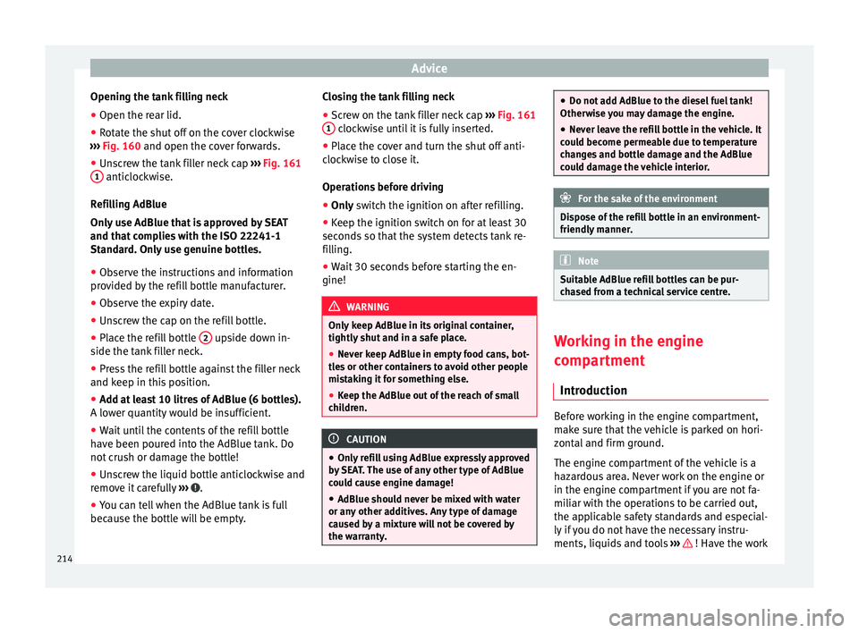
● Open the rear lid.
● Rotate the shut off on the cover clockwise
››› Fig. 160 and open the cover forwards.
● Un s
crew the tank filler neck cap ››› Fig. 161
1 anticlockwise.
Refilling AdBlue
Only use AdBlue that is approved by SEAT
and that complies with the ISO 22241-1
Standard. Only use genuine bottles.
● Observe the instructions and information
provided by the refill bottle manufacturer.
● Observe the expiry date.
● Unscrew the cap on the refill bottle.
● Place the refill bottle 2 upside down in-
side the tank filler neck.
● Press the refill bottle against the filler neck
and keep in this position.
● Add at least 10 litres of AdBlue (6 bottles).
A lower quantity would be insufficient.
● Wait until the contents of the refill bottle
have been poured into the AdBlue tank. Do
not crush or damage the bottle!
● Unscrew the liquid bottle anticlockwise and
remove it carefully ››› .
● You can tell when the AdBlue tank is full
because the bottle will be empty. Closing the tank filling neck
●
Screw on the tank filler neck cap ››› Fig. 161
1 clockwise until it is fully inserted.
● Place the cover and turn the shut off anti-
clockwise to close it.
Operations before driving
● Only switch the ignition on after refilling.
● Keep the ignition sw
itch on for at least 30
seconds so that the system detects tank re-
filling.
● Wait 30 seconds before starting the en-
gine! WARNING
Only keep AdBlue in its original container,
tightly shut and in a safe place.
● Never keep AdBlue in empty food cans, bot-
tles or other containers to avoid other people
mistaking it for something else.
● Keep the AdBlue out of the reach of small
children. CAUTION
● Only refill using AdBlue expressly approved
by SEAT. The use of any other type of AdBlue
could cause engine damage!
● AdBlue should never be mixed with water
or any other additives. Any type of damage
caused by a mixture will not be covered by
the warranty. ●
Do not add AdBlue to the diesel fuel tank!
Otherwise you may damage the engine.
● Never leave the refill bottle in the vehicle. It
could become permeable due to temperature
changes and bottle damage and the AdBlue
could damage the vehicle interior. For the sake of the environment
Dispose of the refill bottle in an environment-
friendly manner. Note
Suitable AdBlue refill bottles can be pur-
chased from a technical service centre. Working in the engine
compartment
Introduction Before working in the engine compartment,
make sure that the vehicle is parked on hori-
zontal and firm ground.
The engine compartment of the vehicle is a
hazardous area. Never work on the engine or
in the engine compartment if you are not fa-
miliar with the operations to be carried out,
the applicable safety standards and especial-
ly if you do not have the necessary instru-
ments, liquids and tools
››› ! Have the work
214
Page 217 of 305
Checking and refilling levels
carried out by a specialised workshop if you
are uncertain. Negligent work can cause seri-
ous injury. WARNING
If the vehicle moves unexpectedly, this could
cause serious injury.
● Never work under the vehicle if it has not
been immobilized. If you must work under-
neath the vehicle with the wheels in contact
with the ground then it should be parked on
flat ground, the wheels should be prevented
from moving and the key should be removed
from the ignition.
● If you have to work underneath the vehicle,
you must use suitable stands additionally to
support the vehicle, there is a risk of acci-
dent!. The jack is not intended for this kind of
work and its failure could lead to severe inju-
ries. WARNING
The engine compartment is a dangerous area
capable of causing serious injury.
● For all type of work, always take the utmost
precautions, work carefully and note the gen-
eral safety standards in force. Never take per-
sonal risks.
● Never work on the engine or in the engine
compartment if you are not familiar with the
necessary operations. If you are not sure
about procedures then visit a specialised
workshop to carry out the necessary work. Working incorrectly can cause serious inju-
ries.
●
Never open the bonnet if you see steam or
coolant escaping from the engine compart-
ment. This may cause serious burns. Always
wait until you cannot see or hear the sound of
steam or coolant coming from the engine
compartment.
● Always allow the engine to cool down be-
fore opening the bonnet.
● Contact with hot elements of the engine
and the exhaust system can cause burns.
● Once the engine has cooled, follow the in-
structions below before opening the bonnet:
– Turn on the electronic parking brake and
place the gear selector lever in P or the
gearbox lever in neutral.
– Remove the key from the ignition.
– Keep children away from the engine com-
partment and never leave them unsuper-
vised.
● When the engine is warm or hot, the cool-
ing system is pressurised. Do not unscrew
the cap on the expansion tank when the en-
gine is hot. Otherwise, coolant may spray out
under pressure causing burns and serious in-
jury.
– Carefully and slowly unscrew the cap an-
ticlockwise, gently pressing down on it.
– Always protect your face, hands and arms
from hot coolant and steam using a large,
thick cloth. ●
When refilling liquids, avoid spilling them
on parts of the engine and the exhaust sys-
tem. Spilled liquids could cause a fire. WARNING
The high voltages of the electrical system can
give electric shocks as well as causing burns
and serious injury and possibly even death!
● Never cause short circuits in the electrical
system. The battery could explode.
● To minimise the risk of electric shock and
serious consequences while the engine is
running or starting the engine, note the fol-
lowing:
– Never touch the electrical wiring of the
ignition system.
– Never touch electric cables or the gas dis-
charge lamps. WARNING
In the engine compartment, there are rotat-
ing parts that could cause serious injury.
● Never place your hands on or near the radi-
ator fan. Touching the rotor blades could seri-
ously harm you. The ventilator works accord-
ing to the engine temperature and could start
suddenly even when the ignition is turned off
and the key is removed.
● If any work has to be performed when the
engine is started or with the engine running,
there is an additional, potentially fatal, safety » 215Technical specifications
Advice
Operation
Safety