phone Seat Alhambra 2015 Owner's Manual
[x] Cancel search | Manufacturer: SEAT, Model Year: 2015, Model line: Alhambra, Model: Seat Alhambra 2015Pages: 305, PDF Size: 5.46 MB
Page 7 of 305
Safe driving
Safety
Safe driving Safety first! This chapter contains important information,
tips, suggestions and warnings that you
should read and consider for both your own
safety and for your passengers' safety.
WARNING
● This manual contains important informa-
tion about the operation of the vehicle, both
for the driver and the passengers. The other
sections of the on-board documentation also
contain further information that you should
be aware of for your own safety and for the
safety of your passengers.
● Ensure that the on-board documentation is
kept in the vehicle at all times. This is espe-
cially important when lending or selling the
vehicle to another person. Tips for driving
Introduction Depending upon how you expect to use your
vehicle, it may a good idea to protect the en-
gine from below. An undercarriage may help to reduce the risk of damage to the lower part
of the vehicle and the oil sump when driving
over kerbs, or along dirt tracks or unsurfaced
roads, etc. SEAT recommends you have the
guard fitted by a technical service centre.
WARNING
Driving under the influence of alcohol, drugs,
medication or narcotics may result in severe
accidents and even loss of life.
● Alcohol, drugs, medication and narcotics
may significantly alter perception, affect re-
action times and safety while driving, which
could result in the loss of control of the vehi-
cle. Before starting every trip
For your own safety and the safety of your
passengers, always note the following points
before every trip:
– Make sure that the vehicle's lights and turn
signals are working properly.
– Check tyre pressure.
– Ensure that all windows provide a clear and
good view of the surroundings.
– Make sure all luggage is secured
››› page 98.
– Make sure that no objects can interfere
with the pedals. –
Adjust front seat, head restraint and rear vi-
sion mirrors properly according to your
size.
– Ensure that the passengers in the rear
seats always have the head restraints in
the in-use position ››› page 90.
– Instruct passengers to adjust the head re-
straints according to their height.
– Protect children with appropriate child
seats and properly applied seat belts
››› page 26 .
– As s
ume the correct sitting position. Instruct
your passengers also to assume a proper
sitting position. ››› page 6.
– Fasten your seat belt securely. Instruct your
passengers also to fasten their seat belts
properly. ››› page 14.
What
affects driving safety? As a driver, you are responsible for yourself
and your passengers. When your concentra-
tion or driving safety is affected by any cir-
cumstance, you endanger yourself as well as
others on the road
››› , for this reason:
– Always pay attention to traffic and do not
get distracted by passengers or telephone calls.
– Never drive when your driving ability is im-
paired (e.g. by medication, alcohol, drugs).
»
5
Technical specifications
Advice
Operation
Safety
Page 23 of 305
Airbag system
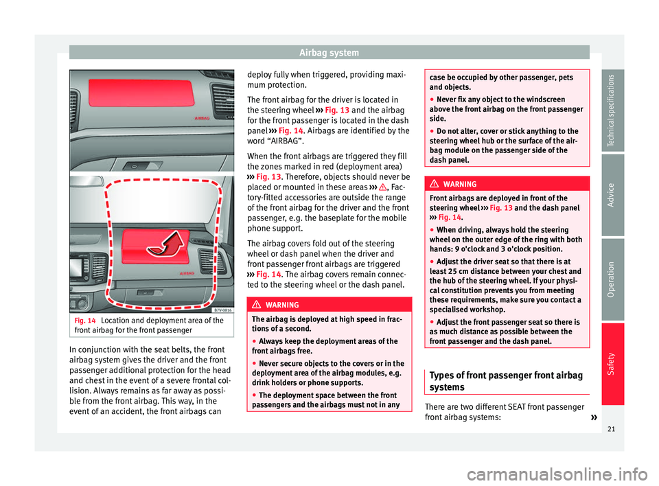
Fig. 14
Location and deployment area of the
front airbag for the front passenger In conjunction with the seat belts, the front
airbag system gives the driver and the front
passenger additional protection for the head
and chest in the event of a severe frontal col-
lision. Always remains as far away as possi-
ble from the front airbag. This way, in the
event of an accident, the front airbags can deploy fully when triggered, providing maxi-
mum protection.
The front airbag for the driver is located in
the steering wheel
››› Fig. 13 and the airbag
f or the fr
ont passenger is located in the dash
panel ››› Fig. 14. Airbags are identified by the
wor
d “AIRBAG”.
When the front airbags are triggered they fill
the zones marked in red (deployment area)
››› Fig. 13. Therefore, objects should never be
pl
aced or mounted in these areas ››› , Fac-
tory-fitted accessories are outside the range
of the front airbag for the driver and the front
passenger, e.g. the baseplate for the mobile
phone support.
The airbag covers fold out of the steering
wheel or dash panel when the driver and
front passenger front airbags are triggered
››› Fig. 14 . The airbag covers remain connec-
t ed t
o the steering wheel or the dash panel. WARNING
The airbag is deployed at high speed in frac-
tions of a second.
● Always keep the deployment areas of the
front airbags free.
● Never secure objects to the covers or in the
deployment area of the airbag modules, e.g.
drink holders or phone supports.
● The deployment space between the front
passengers and the airbags must not in any case be occupied by other passenger, pets
and objects.
●
Never fix any object to the windscreen
above the front airbag on the front passenger
side.
● Do not alter, cover or stick anything to the
steering wheel hub or the surface of the air-
bag module on the passenger side of the
dash panel. WARNING
Front airbags are deployed in front of the
steering wheel ››› Fig. 13
and the dash panel
› ›
› Fig. 14.
● When drivin
g, always hold the steering
wheel on the outer edge of the ring with both
hands: 9 o'clock and 3 o'clock position.
● Adjust the driver seat so that there is at
least 25 cm distance between your chest and
the hub of the steering wheel. If your physi-
cal constitution prevents you from meeting
these requirements, make sure you contact a
specialised workshop.
● Adjust the front passenger seat so there is
as much distance as possible between the
front passenger and the dash panel. Types of front passenger front airbag
systems
There are two different SEAT front passenger
front airbag systems:
»
21
Technical specifications
Advice
Operation
Safety
Page 41 of 305
Cockpit
Operation
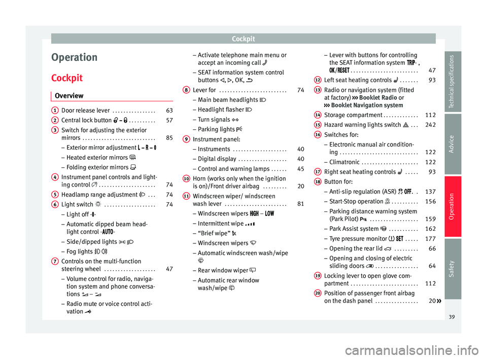
Cockpit Overview Door release lever
. . . . . . . . . . . . . . . . 63
Central lock button . . . . . . . . . . 57
Switch for adjusting the exterior
mirrors . . . . . . . . . . . . . . . . . . . . . . . . . . . 85
– Exterior mirror adjustment
– Heated exterior mirrors
– Folding exterior mirrors
Instrument panel controls and light-
ing control . . . . . . . . . . . . . . . . . . . . . 74
Headlamp range adjustment . . . 74
Light switch . . . . . . . . . . . . . . . . . . . 74
– Light off - -
– Automatic dipped beam head-
light control - -
– Side/dipped lights
– Fog lights
Controls on the multi-function
steering wheel . . . . . . . . . . . . . . . . . . . 47
– Volume control for radio, naviga-
tion system and phone conversa-
tions –
– Radio mute or voice control acti-
vation
1 2
3
4
5
6
7 –
Activate telephone main menu or
accept an incoming call
– SEAT information system control
buttons ,
, OK,
Lever for . . . . . . . . . . . . . . . . . . . . . . . . . 74
– Main beam headlights
– Headlight flasher
– Turn signals
– Parking lights
Instrument panel: – Instruments . . . . . . . . . . . . . . . . . . . . 40
– Digital display . . . . . . . . . . . . . . . . . . 40
– Control and warning lamps . . . . . .45
Horn (works only when the ignition
is on)/Front driver airbag . . . . . . . . .20
Windscreen wiper/ windscreen
wash lever . . . . . . . . . . . . . . . . . . . . . . . 81
– Windscreen wipers –
– Intermittent wipe
– “Brief wipe” x
– Windscreen wipers
– Automatic windscreen wash/wipe
– Rear window wiper
– Automatic rear window
wash/wipe
8
9
10
11 –
Lever with buttons for controlling
the SEAT information system - ,
/
. . . . . . . . . . . . . . . . . . . . . . . . . 47
L ef
t seat heating controls . . . . . . . 93
Radio or navigation system (fitted
at factory) ››› Booklet Radio or
››› Booklet Navigation system
Storage compartment . . . . . . . . . . . . .112
Hazard warning lights switch . . . 242
Switches for: – Electronic manual air condition-
ing . . . . . . . . . . . . . . . . . . . . . . . . . . . . . 122
– Climatronic . . . . . . . . . . . . . . . . . . . . . 122
Right seat heating controls . . . . . 93
Button for: – Anti-slip regulation (ASR) . .137
– Start-Stop operation . . . . . . . . . .156
– Parking distance warning system
(Park Pilot) . . . . . . . . . . . . . . . . . . 159
– Park Assist system . . . . . . . . . . . 162
– Tyre pressure monitor . . . . .177
– Opening the rear lid . . . . . . . . .66
– Opening and closing of electric
sliding doors . . . . . . . . . . . . . . . . 64
Locking lever to open glove com-
partment . . . . . . . . . . . . . . . . . . . . . . . . . 112
Position of passenger front airbag
on the dash panel . . . . . . . . . . . . . . . . 20
»
12 13
14
15
16
17
18
19
20
39
Technical specifications
Advice
Operation
Safety
Page 45 of 305
Cockpit
● Press button three times. The odometer
display flashes on the instrument panel dis-
play.
● Press button 0.0 / SET once. “mph”
or “km/h” is displayed briefly instead of the
odometer.
● This activates the second speed display. To
switch it off, repeat the procedure.
This option cannot be deactivated in models
destined for countries in which the second
speed must always be visible.
Start-Stop operating display.
Updated information relating to the status is
displayed on the instrument panel
››› page 156 . WARNING
Observe the safety warnings ››› in Control
and warning lamps on page 47. WARNING
Even though outside temperatures are above
freezing, some roads and bridges may be icy.
● At outside temperatures above +4°C
(+39°F), even when the “ice crystal symbol”
is not visible, there may still be patches of ice
on the road.
● Never rely on the outside temperature indi-
cator! Note
● Different versions of the instrument panel
are available and therefore the versions and
instructions on the display may vary. In the
case of displays without warning or informa-
tion texts, faults are indicated exclusively by
the warning lamps.
● When several warnings are active at the
same time, the symbols are shown succes-
sively for a few seconds and will stay on until
the fault is rectified. Compass*
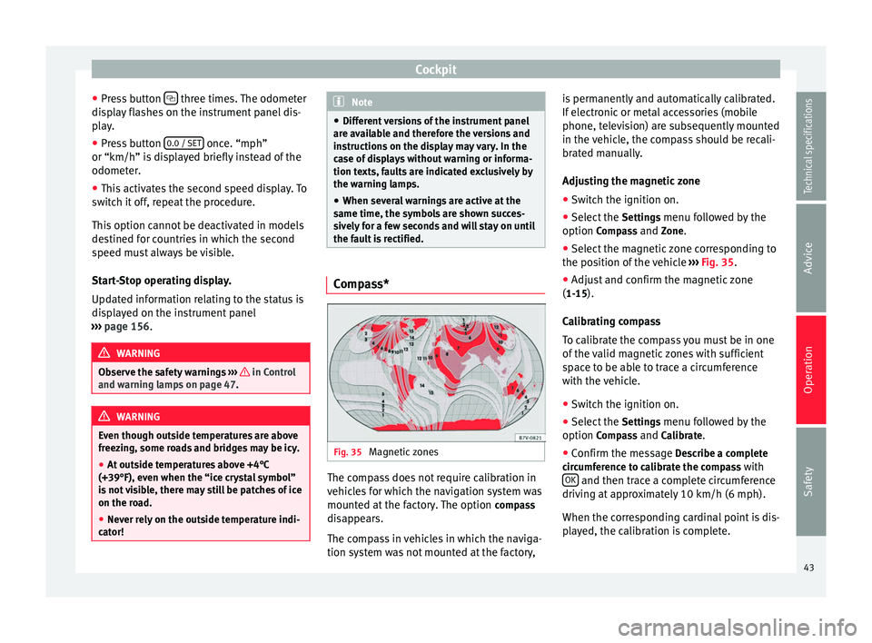
Fig. 35
Magnetic zones The compass does not require calibration in
vehicles for which the navigation system was
mounted at the factory. The option
compass
disappears.
The compass in vehicles in which the naviga-
tion system was not mounted at the factory, is permanently and automatically calibrated.
If electronic or metal accessories (mobile
phone, television) are subsequently mounted
in the vehicle, the compass should be recali-
brated manually.
Adjusting the magnetic zone
● Switch the ignition on.
● Select the Settings menu followed by the
option Compass and Zone.
● Sel ect
the magnetic zone corresponding to
the position of the vehicle ››› Fig. 35.
● Adjus
t and confirm the magnetic zone
(1-15).
Calibrating compass
To calibrate the compass you must be in one
of the valid magnetic zones with sufficient
space to be able to trace a circumference
with the vehicle.
● Switch the ignition on.
● Select the Settings menu followed by the
option Compass and Calibrate.
● Confirm the message Describe a complete
circumference to calibrate the compass with OK and then trace a complete circumference
driving at approximately 10 km/h (6 mph).
When the corresponding cardinal point is dis-
played, the calibration is complete.
43
Technical specifications
Advice
Operation
Safety
Page 49 of 305
Cockpit
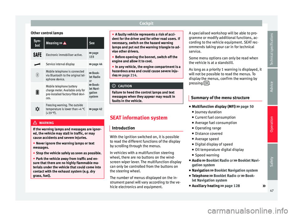
Other control lampsSym- bolMeaning ››› See
Electronic immobiliser active.›››
page
133
Service interval display›››
page 44
Mobile telephone is connected
via Bluetooth to the original tel-
ephone device.›››
Book-
let Radio
or
››› Book-
let Navi-
gation
system
Mobile telephone battery
charge meter. Available only for
pre-installed factory-fitted devi-
ces.
Freezing warning. The outside
temperature is lower than +4 °C
(+39 °F).›››
page 42 WARNING
If the warning lamps and messages are ignor-
ed, the vehicle may stall in traffic, or may
cause accidents and severe injuries.
● Never ignore the warning lamps or text
messages.
● Stop the vehicle safely as soon as possible.
● Park the vehicle away from traffic and en-
sure that there are no highly flammable ma-
terials under the vehicle that could come into
contact with the exhaust system (e.g. dry
grass, fuel). ●
A faulty vehicle represents a risk of acci-
dent for the driver and for other road users. If
necessary, switch on the hazard warning
lamps and put out the warning triangle to ad-
vise other drivers.
● Before opening the bonnet, switch off the
engine and allow it to cool.
● In any vehicle, the engine compartment is a
hazardous area and could cause severe inju-
ries ››› page 214. CAUTION
Failure to heed the control lamps and text
messages when they appear may result in
faults in the vehicle. SEAT information system
Introduction With the ignition switched on, it is possible
to read the different functions of the display
by scrolling through the menus.
In vehicles with a multifunction steering
wheel, there are no buttons on the wind-
screen wiper lever. The multifunction display
can only be controlled from the buttons on
the steering wheel.
The number of menus displayed on the in-
strument panel will vary according to the ve-
hicle electronics and equipment.A specialised workshop will be able to pro-
gramme or modify additional functions, ac-
cording to the vehicle equipment. SEAT rec-
ommends taking your car in for technical
service.
Some menu options can only be read when
the vehicle is at a standstill.
As long as a priority 1 warning is displayed, it
will not be possible to read the menus. To
display the menus, confirm the warning by
pressing
OK .
Summary of the menu structure ■
Multifunction display (MFI) ››› page 50
■ Journey duration
■ Current fuel consumption
■ Average fuel consumption
■ Operating range
■ Distance covered
■ Average speed
■ Digital display of speed
■ Oil temperature digital display
■ Speed warning
■ Audio ›
›
›
Booklet Radio or ›››
Booklet Navi-
gation system
■ Navigation ››
›
Booklet Navigation system
■ Telephone ›››
Booklet Radio or ›››
Book-
let Navigation system
■ Auxiliary heating ››› page 128
»
47
Technical specifications
Advice
Operation
Safety
Page 52 of 305
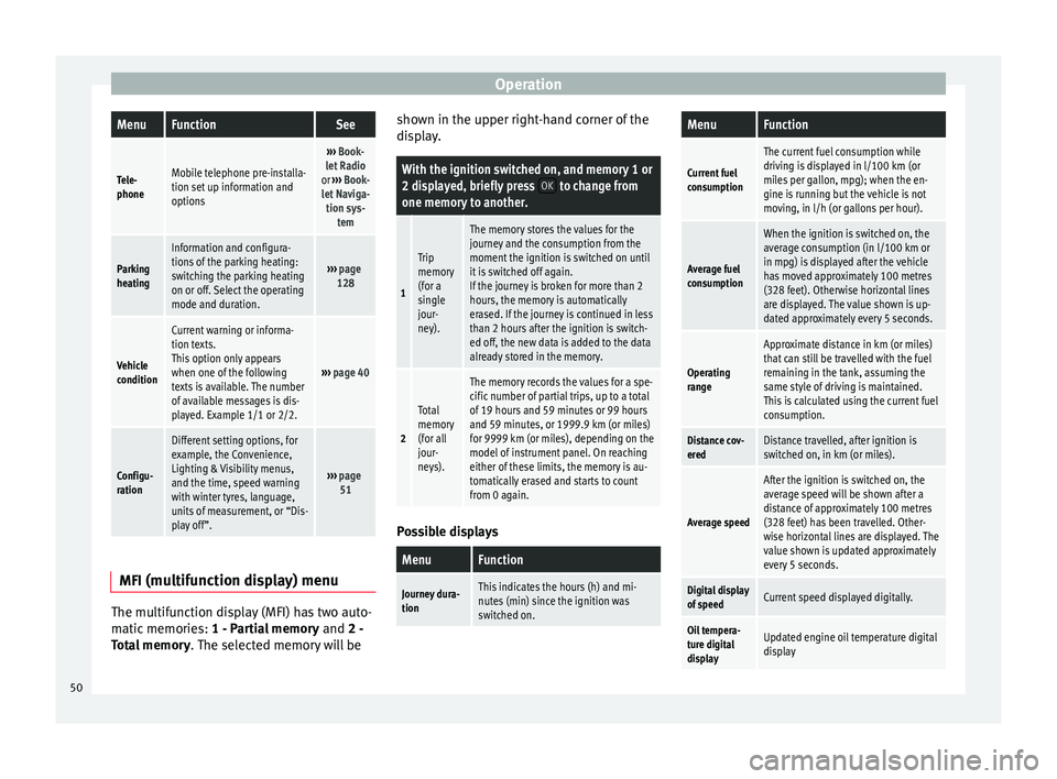
OperationMenuFunctionSee
Tele-
phoneMobile telephone pre-installa-
tion set up information and
options
›››
Book-
let Radio
or ››› Book-
let Naviga- tion sys- tem
Parking
heating
Information and configura-
tions of the parking heating:
switching the parking heating
on or off. Select the operating
mode and duration.
››› page
128
Vehicle
condition
Current warning or informa-
tion texts.
This option only appears
when one of the following
texts is available. The number
of available messages is dis-
played. Example 1/1 or 2/2.
››› page 40
Configu-
ration
Different setting options, for
example, the Convenience,
Lighting & Visibility menus,
and the time, speed warning
with winter tyres, language,
units of measurement, or “Dis-
play off”.
››› page
51 MFI
(multifunction display) menu The multifunction display (MFI) has two auto-
matic memories:
1 - Partial memory and 2 -
T ot
al memory . The selected memory will be shown in the upper right-hand corner of the
display.
With the ignition switched on, and memory 1 or
2 displayed, briefly press
OK to change from
one memory to another.
1
Trip
memory
(for a
single
jour-
ney).
The memory stores the values for the
journey and the consumption from the
moment the ignition is switched on until
it is switched off again.
If the journey is broken for more than 2
hours, the memory is automatically
erased. If the journey is continued in less
than 2 hours after the ignition is switch-
ed off, the new data is added to the data
already stored in the memory.
2
Total
memory
(for all
jour-
neys).
The memory records the values for a spe-
cific number of partial trips, up to a total
of 19 hours and 59 minutes or 99 hours
and 59 minutes, or 1999.9 km (or miles)
for 9999 km (or miles), depending on the
model of instrument panel. On reaching
either of these limits, the memory is au-
tomatically erased and starts to count
from 0 again. Possible displays
MenuFunction
Journey dura-
tionThis indicates the hours (h) and mi-
nutes (min) since the ignition was
switched on.
MenuFunction
Current fuel
consumption
The current fuel consumption while
driving is displayed in l/100 km (or
miles per gallon, mpg); when the en-
gine is running but the vehicle is not
moving, in l/h (or gallons per hour).
Average fuel
consumption
When the ignition is switched on, the
average consumption (in l/100 km or in mpg) is displayed after the vehicle
has moved approximately 100 metres
(328 feet). Otherwise horizontal lines
are displayed. The value shown is up-
dated approximately every 5 seconds.
Operating
range
Approximate distance in km (or miles)
that can still be travelled with the fuel
remaining in the tank, assuming the
same style of driving is maintained.
This is calculated using the current fuel
consumption.
Distance cov-
eredDistance travelled, after ignition is
switched on, in km (or miles).
Average speed
After the ignition is switched on, the
average speed will be shown after a
distance of approximately 100 metres
(328 feet) has been travelled. Other-
wise horizontal lines are displayed. The
value shown is updated approximately
every 5 seconds.
Digital display
of speedCurrent speed displayed digitally.
Oil tempera-
ture digital
displayUpdated engine oil temperature digital
display 50
Page 55 of 305
Cockpit
■ Parking heating menu
■ Configuration Menu
■ Time
■ Language
■ Units
■ Convenience settings menu
■ Door unlock (individual opening, Auto
Lock)
■ Convenience handling of windows
■ Rear vision mirror adjustment
■ Lights & visibility settings menu
■ Coming home and leaving home
■ Footwell light
■ Convenience turn signals
The stored settings are automatically activa-
ted, at the latest when the ignition is switch-
ed on. Please refer to the information and
tips relating to the seat memory
››› page 93 . Thr
ee b utton unit in headliner
Three button module* Fig. 38
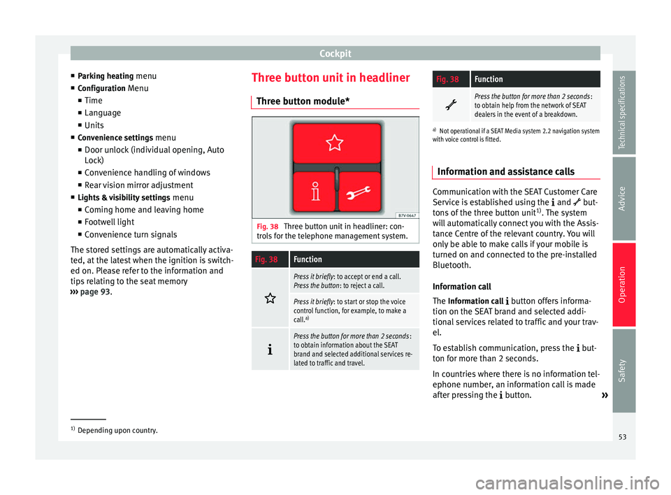
Three button unit in headliner: con-
trols for the telephone management system.
Fig. 38Function
Press it briefly
: to accept or end a call.
Press the button : to reject a call.
Press it briefly: to start or stop the voice
control function, for example, to make a
call. a)
Press the button for more than 2 seconds
:
to obtain information about the SEAT
brand and selected additional services re-
lated to traffic and travel.
Fig. 38Function
Press the button for more than 2 seconds
:
to obtain help from the network of SEAT
dealers in the event of a breakdown.
a) Not operational if a SEAT Media system 2.2 navigation system
with voice control is fitted.
Information and assistance calls Communication with the SEAT Customer Care
Service is established using the
and but-
tons of the three button unit 1)
. The system
will automatically connect you with the Assis-
tance Centre of the relevant country. You will
only be able to make calls if your mobile is
turned on and connected to the pre-installed
Bluetooth.
Information call
The Information call
button offers informa-
tion on the SEAT brand and selected addi-
tional services related to traffic and your trav-
el.
To establish communication, press the but-
ton for more than 2 seconds.
In countries where there is no information tel-
ephone number, an information call is made
after pressing the button. »1)
Depending upon country.
53
Technical specifications
Advice
Operation
Safety
Page 56 of 305
Operation
Assistance call
The assistance call button gives immediate
help in c a
se of a breakdown. To this end, the
SEAT dealer network, with its mobile assis-
tance vehicles, is at your disposal.
To establish communication, press the
button for more than 2 seconds. Note
Calls made with the and
buttons take pri-
ority over normal calls. If the or button is
pr
essed during a normal telephone call, this
call will be cut off and a connection will be
made to the information or assistance centre. Note
Any call made to the information service will
be interrupted if the assistance button is
pr e
ssed. The connection to the assistance
service will then be made (and vice versa). Note
Mobile phone coverage must be available to
place a call to the information and assistance
services. This service might not be available
in some countries. Activating and deactivating
Switching on the speech control system
● Press the button on the multi-function
s t
eering wheel.
● OR:
press the button in the three button
unit in the headliner .
● Wait for the acoustic signal.
● Give the command.
● Follow the dialogue instructions (extended
dialogue).
Ending voice control
● Press the button on the multi-function
steering wheel.
● OR: press the button in the three button
u nit
in the headliner .
Interrupting the instructions
● During the instructions, press the button
on the multi-function steering wheel.
● OR:
press the button in the three button
unit in the headliner .
● You will be able to give a command imme-
diately afterwards. Opening and closing
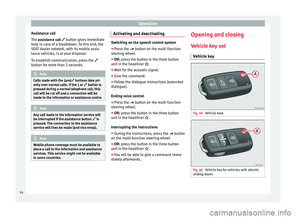
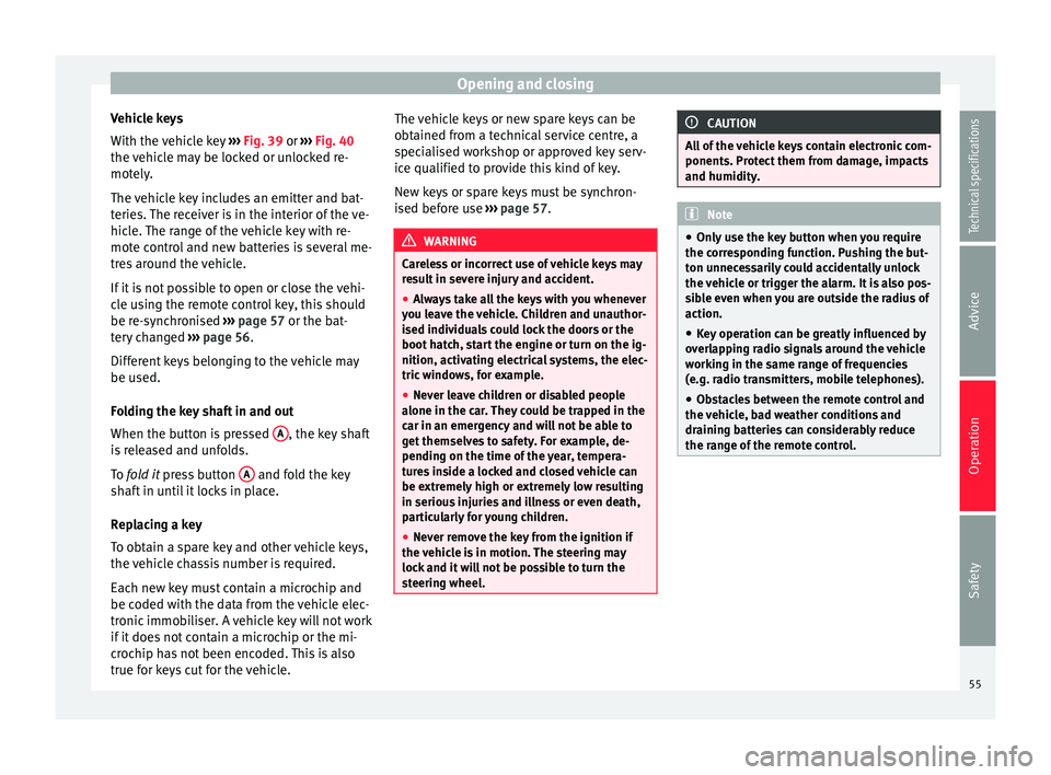
Vehicle key set Vehicle key Fig. 39
Vehicle keys Fig. 40
Vehicle key for vehicles with electric
sliding doors 54
Page 57 of 305
Opening and closing
Vehicle keys
With the vehicle key ››› Fig. 39 or
›
›› Fig. 40
the
vehicle may be locked or unlocked re-
motely.
The vehicle key includes an emitter and bat-
teries. The receiver is in the interior of the ve-
hicle. The range of the vehicle key with re-
mote control and new batteries is several me-
tres around the vehicle.
If it is not possible to open or close the vehi-
cle using the remote control key, this should
be re-synchronised ››› page 57 or the bat-
tery changed ››› page 56.
Differ
ent keys belonging to the vehicle may
be used.
Folding the key shaft in and out
When the button is pressed A , the key shaft
is released and unfolds.
To fold it
press button A and fold the key
shaft in until it locks in place.
Replacing a key
To obtain a spare key and other vehicle keys,
the vehicle chassis number is required.
Each new key must contain a microchip and
be coded with the data from the vehicle elec-
tronic immobiliser. A vehicle key will not work
if it does not contain a microchip or the mi-
crochip has not been encoded. This is also
true for keys cut for the vehicle. The vehicle keys or new spare keys can be
obtained from a technical service centre, a
specialised workshop or approved key serv-
ice qualified to provide this kind of key.
New keys or spare keys must be synchron-
ised before use
››› page 57. WARNING
Careless or incorrect use of vehicle keys may
result in severe injury and accident.
● Always take all the keys with you whenever
you leave the vehicle. Children and unauthor-
ised individuals could lock the doors or the
boot hatch, start the engine or turn on the ig-
nition, activating electrical systems, the elec-
tric windows, for example.
● Never leave children or disabled people
alone in the car. They could be trapped in the
car in an emergency and will not be able to
get themselves to safety. For example, de-
pending on the time of the year, tempera-
tures inside a locked and closed vehicle can
be extremely high or extremely low resulting
in serious injuries and illness or even death,
particularly for young children.
● Never remove the key from the ignition if
the vehicle is in motion. The steering may
lock and it will not be possible to turn the
steering wheel. CAUTION
All of the vehicle keys contain electronic com-
ponents. Protect them from damage, impacts
and humidity. Note
● Only use the key button when you require
the corresponding function. Pushing the but-
ton unnecessarily could accidentally unlock
the vehicle or trigger the alarm. It is also pos-
sible even when you are outside the radius of
action.
● Key operation can be greatly influenced by
overlapping radio signals around the vehicle
working in the same range of frequencies
(e.g. radio transmitters, mobile telephones).
● Obstacles between the remote control and
the vehicle, bad weather conditions and
draining batteries can considerably reduce
the range of the remote control. 55
Technical specifications
Advice
Operation
Safety
Page 65 of 305
Opening and closing
monitoring function (arrow) is not guaran-
teed to work freely.
Use the key to lock the vehicle. If the anti-
theft alarm is turned on, the interior monitor-
ing and the anti-tow systems are also activa-
ted.
Switching off the interior monitoring and the
anti-tow systems
The interior monitoring is switched off by
pressing the remote control lock button twice.
● Lock all doors and rear lid.
● Use the key to lock the vehicle. The interior
monitoring and / or anti-towing alarm are
switched off until the next time the vehicle is
locked.
To turn off the interior monitoring and anti-
tow systems before unlocking the vehicle, for
example in the following situations:
● When leaving animals inside the vehicle
››› page 57 .
● When the v
ehicle must be loaded.
● When the vehicle is being transported, for
example, by ferry.
● When the vehicle must be towed with the
axle raised. Risk of false alarms
The interior monitoring system will only oper-
ate correctly if the vehicle is completely
closed. Observe legal requirements. The
alarm may be accidentally triggered in the
following cases:
●
When a window is completely or partially
open.
● If the sunglasses storage compartment in
the roof console is open.
● When the panoramic sliding sunroof is
completely or partially open.
● When suspended objects are hung from
the interior mirror (air freshener) or there are
loose papers in the vehicle.
● If the separation net is fitted and moves
(due to heating).
● Due to a vibrating mobile telephone inside
the vehicle. Note
Upon activating the alarm, if any door or the
rear lid is open, only the anti-theft alarm will
be activated. The interior monitoring and an-
ti-tow systems will only be activated when
the doors and rear lid are fully closed. Doors
Introduction WARNING
If a door is not correctly closed, it could open
unexpectedly when driving and cause serious
injuries.
● Always stop immediately and close the
door.
● When closing, ensure that the door has
closed correctly. A closed door should be
flush with the corresponding parts of the
bodywork.
● Open and close doors only when nobody is
in the way of the door. WARNING
A door held open by its retainer could be
blown closed by the wind or close if the vehi-
cle is on a hill, causing injury.
● When opening and closing doors, always
use the door handle. 63
Technical specifications
Advice
Operation
Safety