technical data Seat Altea 2010 Owner's Manual
[x] Cancel search | Manufacturer: SEAT, Model Year: 2010, Model line: Altea, Model: Seat Altea 2010Pages: 310, PDF Size: 7.46 MB
Page 241 of 310
Checking and refilling levels239
Safety First
Operating instructions
Practical tips
Technical Data
Brake fluidChecking the brake fluid level
The brake fluid is checked at the intervals given in the service
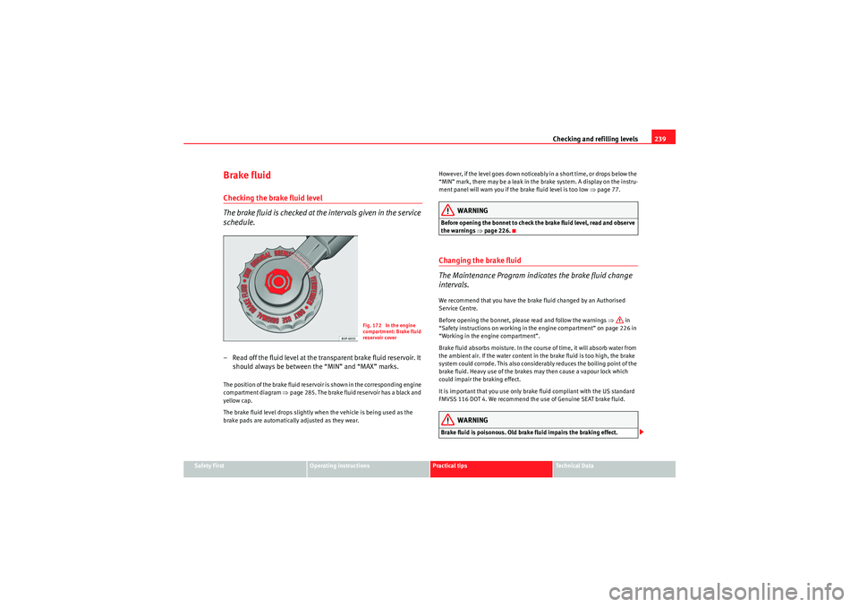
schedule.– Read off the fluid level at the transparent brake fluid reservoir. It
should always be between the “MIN” and “MAX” marks.The position of the brake fluid reservoir is shown in the corresponding engine
compartment diagram ⇒page 285. The brake fluid reservoir has a black and
yellow cap.
The brake fluid level drops slightly when the vehicle is being used as the
brake pads are automatically adjusted as they wear. However, if the level goes down noticeably in a short time, or drops below the
“MIN” mark, there may be a leak in the brake system. A display on the instru-
ment panel will warn you if the brake fluid level is too low ⇒
page 77.
WARNING
Before opening the bonnet to check the brake fluid level, read and observe
the warnings ⇒page 226.Changing the brake fluid
The Maintenance Program indicates the brake fluid change
intervals.We recommend that you have the brake fluid changed by an Authorised
Service Centre.
Before opening the bonnet, please read and follow the warnings ⇒ in
“Safety instructions on working in the engine compartment” on page 226 in
“Working in the engine compartment”.
Brake fluid absorbs moisture. In the course of time, it will absorb water from
the ambient air. If the water content in the brake fluid is too high, the brake
system could corrode. This also considerably reduces the boiling point of the
brake fluid. Heavy use of the brakes may then cause a vapour lock which
could impair the braking effect.
It is important that you use only brake fluid compliant with the US standard
FMVSS 116 DOT 4. We recommend the use of Genuine SEAT brake fluid.
WARNING
Brake fluid is poisonous. Old brake fluid impairs the braking effect.
Fig. 172 In the engine
compartment: Brake fluid
reservoir cover
altea_EN Seite 239 Mittwoch, 26. August 2009 6:00 18
Page 243 of 310
Checking and refilling levels241
Safety First
Operating instructions
Practical tips
Technical Data
charge. Never short the battery terminals. High-energy sparks can cause
injury.
•A highly explosive mixture of gases is released when the battery is
under charge. The batteries should be charged in a well-ventilated room
only.•Keep children away from acid and batteries.•Before working on the electrical system, you must switch off the
engine, the ignition and all consumers. The negative cable on the battery
must be disconnected. When a light bulb is changed, you need only switch
off the light.•Deactivate the anti-theft alarm by unlocking the vehicle before you
disconnect the battery! The alarm will otherwise be triggered.•When disconnecting the battery from the vehicle electrical system,
disconnect first the negative cable and then the positive cable.•Switch off all electrical consumers before reconnecting the battery.
Reconnect first the positive cable and then the negative cable. Never
reverse the polarity of the connections. This could cause an electrical fire.•Never charge a frozen battery, or one which has thawed. This could
result in explosions and chemical burns. Always replace a battery which
has frozen. A flat battery can freeze at temperatures around 0°•Ensure that the vent hose is always connected to the battery.•Never use a defective battery. This may be fatally explosive. Replace a
damaged battery immediately.Caution
•Never disconnect the battery if the ignition is switched on or if the engine
is running. This could damage the electrical system or electronic compo-
nents.•Do not expose the battery to direct sunlight over a long period of time, as
the intense ultraviolet radiation can damage the battery housing.
•If the vehicle is left standing in cold conditions for a long period, protect
the battery from frost. If it “freezes” it will be damaged.Checking the electrolyte level
The electrolyte level should be checked regularly in high-
mileage vehicles, in hot countries and in older batteries.– Open the bonnet and open the battery cover at the front ⇒ in
“Safety instructions on working in the engine compartment” on
page 226 ⇒ in “Warnings on handling the battery” on
page 240.
– Check the colour display in the "magic eye" on the top of the battery.
– If there are air bubbles in the window, tap the window gently until they disperse.The position of the battery is shown in the corresponding engine compart-
ment diagram ⇒ page 285.
The “magic eye” indicator, located on the top of the battery changes colour,
depending on the charge state and electrolyte level of the battery.
There are two different colours:•Black: correct charge status.•Transparent/clear yellow: the battery must be replaced. Contact a
specialist workshop.
WARNING (continued)
altea_EN Seite 241 Mittwoch, 26. August 2009 6:00 18
Page 245 of 310
Wheels and tyres243
Safety First
Operating instructions
Practical tips
Technical Data
Wheels and tyresWheelsGeneral notesAvoiding damage
– If you have to drive over a kerb or similar obstacle, drive very
slowly and as near as possible at a right angle to the kerb.
– Keep grease, oil and fuel off the tyres.
– Inspect the tyres regularly for damage (cuts, cracks or blisters, etc.). Remove any foreign objects embedded in the treads.
Storing tyres
– Mark tyres when you remove them to indicate the direction of rotation. This ensures you will be able to install them correctly
when you replace them.
– When removed, the wheels and/or tyres should be stored in a cool, dry and preferably dark location.
– Store tyres in a vertical position if they are not fitted on wheel rims.New tyres
New tyres have to be run in ⇒page 200.
The tread depth of new tyres may vary, according to the type and make of tyre
and the tread pattern. Concealed damage
Damage to tyres and rims is often not readily visible. If you notice unusual
vibrations or the car pulling to one side, this may indicate that one of the tyres
is damaged. The tyres should be checked immediately by an Authorised
Service Centre.
Tyres with directional tread pattern
An arrow on the tyre sidewall indicates the direction of rotation on tyres with
directional tread. Always observe the direction of rotation indicated when
fitting the wheel. This guarantees optimum grip and helps to avoid aqua-
planing, excessive noise and wear.
WARNING
•New tyres do not have maximum grip in the first 500 km. Drive particu-
larly carefully to avoid risk of accident.•Never drive with damaged tyres. This may cause an accident.•If you notice unusual vibration or if the vehicle pulls to one side when
driving, stop the vehicle immediately and check the tyres for damage.
Checking tyre pressure
The correct tyre pressure can be seen on the sticker on the
inside of the tank flap.1. Read the required tyre inflatio n pressure from the sticker. The
values refer to Summer tyres. For Winter tyres, you must add 0.2
bar to the values given on the sticker.
altea_EN Seite 243 Mittwoch, 26. August 2009 6:00 18
Page 247 of 310
Wheels and tyres245
Safety First
Operating instructions
Practical tips
Technical Data
For the sake of the environment
Under-inflated tyres lead to increased fuel consumption and tyre wear.Significant tyre pressure lossThe tyre symbol
is displayed and indicates that the tyre pressure for a least
one tyre is insufficient.
– Stop the vehicle.
– Switch the engine off.
– Check the tyre(s).
– Change the wheel if necessary.
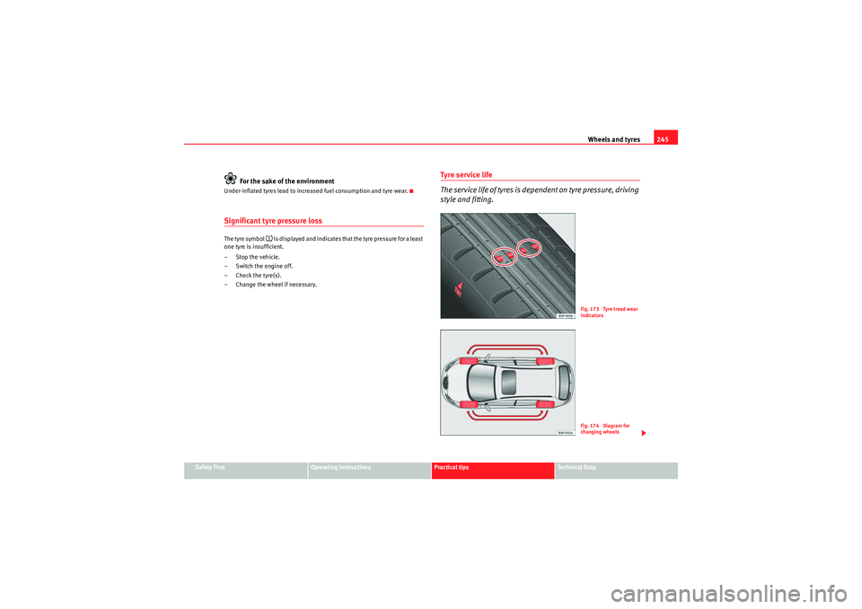
Tyre s e r vi ce l ife
The service life of tyres is dependent on tyre pressure, driving
style and fitting.
Fig. 173 Tyre tread wear
indicatorsFig. 174 Diagram for
ch anging w hee ls
altea_EN Seite 245 Mittwoch, 26. August 2009 6:00 18
Page 249 of 310
Wheels and tyres247
Safety First
Operating instructions
Practical tips
Technical Data
Driving with anti-puncture tyres (emergency gear)
– Leave the ESP/TCS (electronic stabilisation programme)
switched on, or switch on ⇒page 194.
– Continue driving carefully and slowly (80 km/h maximum).
– Avoid sudden manoeuvres and sharp turns.
– Avoid driving over obstacles (for example kerbs) or potholes.
– Look out for the ESP/TCS intervening often, smoke coming from the tyres or the smell of rubber, the vehicle vibrating or a clat-
tering noise. If any of these occur, stop the vehicle.The anti-puncture tyres have a tag on the side of the tyre, with the description:
“DSST”, “Eufonia”, “RFT”, “ROF”, “RSC”, “SSR” or “ZP”.
The sides of this type of tyre are reinforced. When the tyres lose air they are
supported on the sides (emergency driving).
The loss of pressure in the tyre is shown on the instrument panel. You can
then drive a maximum of 80 km and if the circumstances are favourable (for
example, low load), even more.
The damaged tyre should be changed as soon as possible. The rim should be
checked in a specialist workshop to detect possible damage and replace it if
necessary. We recommend you contact Technical Service. If more than one
tyre is being used under emergency conditions, this reduces the distance
which can be travelled.
Starting driving in emergency conditions
When the loss in tyre pressure is displayed on the instrument panel, this
implies that at least one tyre is being driven in emergency conditions ⇒.
End of emergency operation
Do not drive on if:
•smoke is coming from one of the tyres,•there is a smell of rubber,•the vehicle vibrates,•there is a rattling noise.
When is it no longer possible to continue driving even using anti-puncture
tyres?•If one of the tyres has been severely damaged in an accident, etc. If a tyre
has been badly damaged there is a risk that parts of the tread can be thrown
off and cause damage to the fuel lines, brake pipes or fuel filler.•It is also advisable to stop driving if severe vibrations occur, or if the wheel
starts overheating and gives off smoke.WARNING
When driving in emergency conditions, the driving quality of the vehicle is
considerably impaired.•The maximum permitted speed of 80 km/h is subject to road and
weather conditions. Please observe legal requirements when doing so.•Avoid sharp turns and rapid manoeuvres, and brake earlier than usual.•Avoid driving over obstacles (for example kerbs) or potholes.•If one or more tyres is being driven in emergency conditions, the driving
quality of the vehicle is impaired and there is a risk of accident.Note
•The anti-puncture tyres do not “deflate” on losing pressure because they
are supported on the reinforced sides. Therefore defects in the tyre can not be
detected with a visual inspection.•Snow chains must not be used on front tyres used in emergency
conditions.
altea_EN Seite 247 Mittwoch, 26. August 2009 6:00 18
Page 251 of 310
Wheels and tyres249
Safety First
Operating instructions
Practical tips
Technical Data
Wheel bolts
Wheel bolts must be tightened to the correct torque.The design of wheel bolts is matched to the rims. If different wheel rims are
fitted, the correct wheel bolts with the right length and correctly shaped bolt
heads must be used. This ensures that wheels are fitted securely and that the
brake system functions correctly.
In certain circumstances, you may not use wheel bolts from a different car -
even if it is the same model ⇒ page 218.
After the wheels have been changed, the tightening torque of the wheel bolts
should be checked as soon as possible with a torque wrench ⇒. The tight-
ening torque for steel and alloy wheels is 120 Nm.
WARNING
If the wheel bolts are not tightened correctly, the wheel could become
loose while driving. Risk of accident.•The wheel bolts must be clean and turn easily. Never apply grease or oil
to them.•Use only wheel bolts which belong to the wheel.•If the torque of the wheel bolts is too low, they could loosen whilst the
vehicle is in motion. Risk of accident! If the tightening torque is too high,
the wheel bolts and threads can be damaged.Caution
The prescribed torque for wheel bolts for steel and alloy wheels is 120 Nm.
Winter tyres
Winter tyres will improve the vehicles handling on snow and
ice.In winter conditions winter tyres will considerably improve the vehicles
handling. The design of summer tyres (width, rubber compound, tread
pattern) gives less grip on ice and snow.
Winter tyres must be inflated to a pressure 0.2 bar higher than the pressures
specified for summer tyres (see sticker on tank flap).
Winter tyres must be fitted on all four wheels.
Information on permitted winter tyre sizes can be found in the vehicle's regis-
tration documents. Use only radial winter tyres. All tyre sizes listed in the
vehicle documentation also apply to winter tyres.
Winter tyres lose their effectiveness when the tread is worn down to a depth
of 4 mm.
The speed rating code ⇒ page 248, “New tyres and wheels” determines the
following speed limits for winter tyres: ⇒
Q max. 160 km/h
S max. 180 km/h
T max. 190 km/h
H max. 210 km/h
In some countries, vehicles which can exceed the speed rating of the fitted
tyre must have an appropriate sticker in the driver's field of view. These
stickers are available from your Authorised Service Centre. The legal require-
ments of each country must be followed.
Do not have winter tyres fitted for unnecessarily long periods. Vehicles with
summer tyres handle better when the roads are free of snow and ice.
If you have a flat tyre, please refer to the notes on the spare wheel
⇒ page 248, “New tyres and wheels”.
altea_EN Seite 249 Mittwoch, 26. August 2009 6:00 18
Page 253 of 310
If and when251
Safety First
Operating instructions
Practical tips
Technical Data
If and whenTools, tyre repair kit and spare wheelVehicle Tools
The vehicle onboard tools are located under the floor panel in
the luggage compartment.– Lift the cover of the luggage compartment, by pulling it up with a
finger in the fitting.
– Take the onboard tools out of the vehicle.The tool kit includes:•Jack*•Hook for removing wheel covers* or hub caps*•Box spanner for wheel bolts*•Reversible screwdriver with handle (including hexagonal interior) for the
wheel bolts. The screwdriver is a combination tool.•To wi n g e ye•Adapter for the anti-theft wheel bolts*
Some of the items listed are only provided in certain models / model years,
or are optional extras.WARNING
•Do not use the hexagonal socket in the screwdriver handle to tighten
the wheel bolts as with this it is not possible to tighten the bolts to the
required torque. Risk of accident.
•The jack supplied by the factory is only designed for changing wheels
on this model. On no account attempt to use it for lifting heavier vehicles
or other loads. Risk of injury.•Use the jack only on a firm, level ground.•Never start the engine when the vehicle is on the jack. Risk of accident.•If work is to be carried out underneath the vehicle, this must be secured
by suitable stands. Otherwise, there is a risk of injury.WARNING (continued)
altea_EN Seite 251 Mittwoch, 26. August 2009 6:00 18
Page 255 of 310
If and when253
Safety First
Operating instructions
Practical tips
Technical Data
reliably seal punctures up to a size of about 4 mm caused by the penetration
of a foreign body into the tyre.
Note
•Seek professional assistance if the repair of a tyre puncture is not
possible with the sealing compound.Wheel changePreparation work
What you must do before changing a wheel.– If you have a flat tyre or puncture, park the vehicle as far away from the flow of traffic as possible. Choose a location that is as
level as possible.
– All passengers should leave the vehicle. They should wait in a safe area (for instance behind the roadside crash barrier).
– Switch off the engine. Switch on the hazard warning lights.
– Apply the handbrake firmly.
– Engage the first gear, or put the selector lever to position P for
those vehicles with an automatic gearbox.
– If you are towing a trailer, unhitch it from your vehicle.
–Take the vehicle tools and the spare wheel out of the luggage
compartment.
WARNING
Put the hazard warning lights on and place the warning triangle in position.
This is for your own safety and also warns other road users.
Caution
If you have to change the tyre on a gradient, block the wheel opposite the
wheel being changed by placing a stone or similar object under it to prevent
the vehicle from rolling away.
Note
Please observe legal requirements when doing so.Changing a wheelChange the wheel as described below
– Remove the wheel cover. Also refer to ⇒page 254, fig. 176 .
–Slacken the wheel bolts .
– Raise the car with the jack in the corresponding zone.
– Remove the wheel and then put on the spare wheel.
– Lower the vehicle.
– Tighten the wheel bolts firmly with the box spanner.
–Replace the hub cap.
altea_EN Seite 253 Mittwoch, 26. August 2009 6:00 18
Page 257 of 310
If and when255
Safety First
Operating instructions
Practical tips
Technical Data
Wheel covers*
The wheel covers must be removed for access to the wheel
boltsRemoving
– Remove the wheel cover using the wire hook.
– Hook this into one of the cut-outs of the wheel cover.
Fitting
– Fit the wheel cover onto the wheel rim by pressing it firmly. Put
pressure initially on the point of the cut-out for the valve. Then
press the wheel cover onto the steel rim so that it engages all
round.
Loosening the wheel bolts
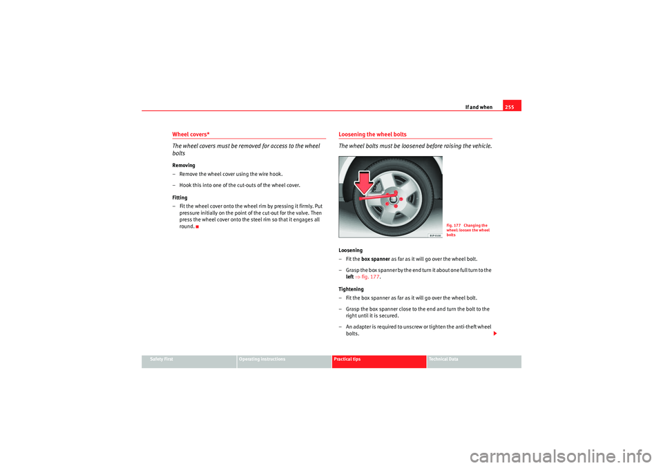
The wheel bolts must be loosened before raising the vehicle.Loosening
–Fit the box spanner as far as it will go over the wheel bolt.
– Grasp the box spanner by the end turn it about one full turn to the left ⇒ fig. 177 .
Tightening
– Fit the box spanner as far as it will go over the wheel bolt.
– Grasp the box spanner close to the end and turn the bolt to the right until it is secured.
– An adapter is required to unscrew or tighten the anti-theft wheel bolts.
Fig. 177 Changing the
wheel: loosen the wheel
bolts
altea_EN Seite 255 Mittwoch, 26. August 2009 6:00 18
Page 259 of 310
If and when257
Safety First
Operating instructions
Practical tips
Technical Data
Raising the vehicle
In order to remove the wheel, the vehicle must be raised with
a jack.
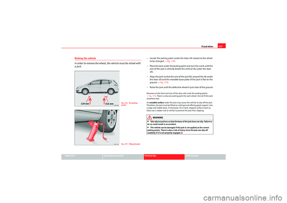
– Locate the jacking point under the door sill closest to the wheel
to be changed ⇒fig. 178 .
– Place the jack under the jacking point and turn the crank until the arm of the jack is directly below the vertical rib under the door
sill.
– Align the jack so that the arm of the jack fits around the rib under the door sill and the movable base plate of the jack is flat on the
ground ⇒fig. 179 .
– Raise the jack until the defective wheel is just clear of the ground.Recesses at the front and rear of the door sills mark the jacking points
⇒ fig. 178 . There is only one jacking point for each wheel. Do not fit the jack
anywhere else.
An unstable surface under the jack may cause the vehicle to slip off the jack.
Therefore, the jack must be fitted on solid ground offering good support. Use
a large and stable base, if necessary. On a hard, slippery surface (such as
tiles) use a rubber mat or similar to prevent the jack from slipping.
WARNING
•Take all precautions so that the base of the jack does not slip. Failure to
do so could result in an accident.•The vehicle can be damaged if the jack is not applied at the correct
jacking points. There is also a risk of injury since the jack can slip off
suddenly if it is not properly engaged.
Fig. 178 The jacking
pointsFig. 179 Fitting the jack
altea_EN Seite 257 Mittwoch, 26. August 2009 6:00 18